


contents
connections 6
remote 19
features 20
menus 25
FAQs 30
warranty 36
user’s guide
| LCD FLAT PANEL HDTV
For use with models: L32HD41/L32HD31R
Need assistance? visit our website at www.rca.com/tv or call 1-877-794-7977
Important Information
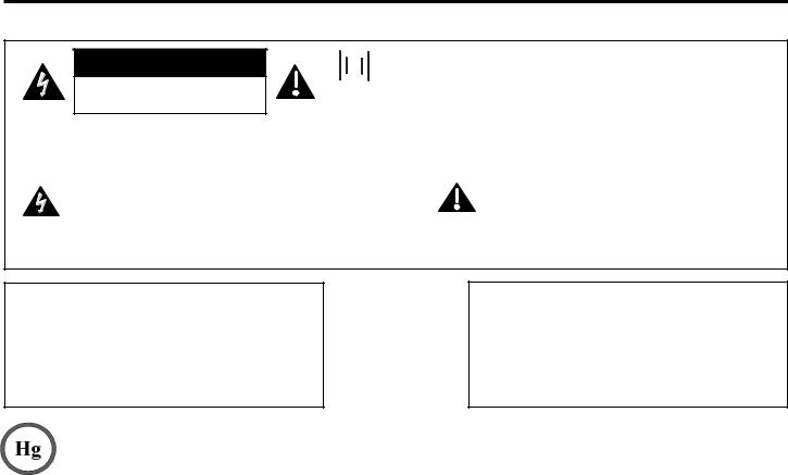
CAUTION
RISK OF ELECTRIC SHOCK. DO NOT OPEN
 This symbol indicates that this product incorporates double
  insulation between hazardous main voltage and user accessible parts. When servicing, use only identical replacement parts.
Caution: To reduce the risk of electric shock, do not remove cover (or back). No user serviceable parts inside. Refer servicing to qualified service personnel.
This symbol indicates "dangerous voltage" inside the product that presents a risk of electric shock or personal injury.
This symbol indicates important instructions accompanying the product.
WARNING
To reduce the risk of fire or electric shock, do not expose this product to rain or moisture. This product should not be exposed to dripping or splashing. No objects filled with liquids, such as vases, should be placed on the component.
WARNING
The TV is unstable if it is not properly attached to the base or mounted to the wall. Please follow the base or wall mounting instructions provided in the User’s Guide to ensure your safety.
This symbol indicates that this product contains mercury. Special disposal of this product for environmental reasons may be required under the laws applicable to your jurisdiction. For disposal or recycling information, please contact your local authorities or the Electronic Industries Alliance: www.eiae.org.
Refer to the identification/rating label located on the back panel of your product for its proper operating voltage.
FCC regulations state that changes or modifications to this unit not expressly approved by the party responsible for compliance could void the user’s authority to operate the equipment.
Cable TV Installer: This reminder is provided to call your attention to Article 820-40 of the National Electrical Code (Section 54 of the Canadian Electrical Code, Part 1) which provides guidelines for proper grounding and, in particular, specifies that the cable ground should be connected to the grounding system of the building as close to the point of cable entry as practical.
Important: This television is a table model and is designed to sit on a firm, flat surface. Don’t place the TV on soft carpeting or a similar surface, as the ventilation slots on the bottom of the unit may be blocked, resulting in reduced lifetime from overheating. To assure adequate ventilation for this product, maintain a spacing of 4 inches from the top and sides of the TV receiver and 2 inches from the rear of the TV receiver and other surfaces.
Also, make sure the surface or stand is of adequate size and strength to prevent the TV from being accidentally tipped over, pushed off, or pulled off. This could cause personal injury and/or damage to the TV. Refer to the Important Safety Instructions on the next page.
The power button (followed by the power symbol) on this TV and your remote control puts the TV into a very low-power standby mode but will not completely shut the power off. In order to shut the power off, you will need to disconnect the power cord from your outlet. Therefore, you should make sure the TV is installed in a way that allows you to disconnect the power cord when desired.
Product Registration
Please fill out the product registration card (packed separately) and return it immediately. For US customers: Your RCA Consumer Electronics product may also be registered at www.rca.com/television. Registering this product allows us to contact you if needed.
Product Information
Keep your sales receipt to obtain warranty parts and service and for proof of purchase. Attach it here and record the serial and model numbers in case you need them. These numbers are located on the product.
Model No. ___________________________ Serial No.______________________ Purchase Date __________________
Dealer/Address/Phone ______________________________________________________________________________
Important Safety Instructions
1.Read and follow all instructions.
2.Do not block any ventilation openings. Install in accordance with the manufacturer’s instructions.
3.Do not install near any heat sources such as radiators, heat registers, stoves, or other apparatus (including amplifiers) that produce heat.
4.Do not negate the safety purpose of the polarized or grounding-type plug. A polarized plug has two blades with one wider than the other. A grounding type plug has two blades and a third grounding prong. The wide blade or the third prong is provided for your safety. If the provided plug does not fit your outlet, consult an electrician for replacement of the obsolete outlet.
5.Protect the power cord from being walked on or pinched particularly at plugs, receptacles, and the point where it exits from the component.
6.Do not use this component near water.
7.Only use the attachments/accessories specified by the manufacturer.
8.Clean only with dry cloth.
9.Use only with the cart, stand, tripod, bracket, or table specified by the manufacturer, or sold with the component. When the TV is placed on a cart, use caution when moving the cart to avoid injury from tip-over.
10.Unplug this component during lightning storms or when unused for long periods of time.
11.Refer all servicing to qualified service personnel. Service is required when the component is damaged in any way, such as power supply cord or plug damage, liquid spilled on or objects falling onto the component, rain or moisture exposure, abnormal operation, or if the component has been dropped.
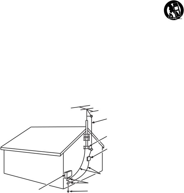
12.If an outside antenna or cable system is connected to the product, be sure the antenna or cable system is grounded so as to provide some protection against voltage surges and built-up static charges. Section 810 of the National Electrical Code, ANSI/NFPA No. 70-1984 (Section 54 of Canadian Electrical Code, Part 1) provides information with respect to proper grounding of the mast and supporting structure, grounding of the lead-in wire to an antenna-discharge unit, size of grounding conductors, location of antenna-discharge unit, connection to grounding electrodes, and requirements for the grounding electrode. See following example:
ANTENNA
LEAD IN
WIRE
GROUND CLAMP
ANTENNA DISCHARGE UNIT
(NEC SECTION 810-20)
|
GROUNDING CONDUCTORS |
|
(NEC SECTION 810-21) |
|
GROUND CLAMPS |
ELECTRIC SERVICE |
POWER SERVICE GROUNDING |
EQUIPMEN T |
ELECTRODE SYSTEM |
|
(NEC ART 250, PARTH) |

Table of Contents |
|
Important Information ................................................................................................................................. |
i |
Important Safety Instructions ...................................................................................................................... |
i |
Chapter 1 I Connections and Setup |
|
Before Initial Setup .......................................................................................................................... |
6 |
Protect Against Power Surges ............................................................................................................ |
6 |
Safety Information .............................................................................................................................. |
6 |
Avoid Audio Interference .................................................................................................................... |
6 |
Avoid Direct Light ............................................................................................................................... |
6 |
Check Supplied Parts ........................................................................................................................ |
6 |
Attaching Your TV to the Table Stand ............................................................................................. |
7 |
Mounting Your TV to the Wall .......................................................................................................... |
7 |
Obtain the Signal.............................................................................................................................. |
8 |
What You Need .................................................................................................................................. |
8 |
What You Need to Know .................................................................................................................... |
8 |
Choose Your Connections ............................................................................................................... |
9 |
Connecting a Component with Composite Video (Good) ................................................................... |
10 |
Connecting a Component with Component Video (Better) ................................................................ |
10 |
Connecting a Component with HDMI (Best) ...................................................................................... |
11 |
Connecting a PC Component ........................................................................................................... |
12 |
Viewing the Picture from the Connected Component ........................................................................ |
13 |
Viewing a PC..................................................................................................................................... |
13 |
Plug in the TV .................................................................................................................................. |
14 |
Put Batteries in the Remote ........................................................................................................... |
14 |
Turn on the TV ................................................................................................................................. |
14 |
Using the Remote Control to Complete Initial Setup .................................................................... |
14 |
Complete the Initial Setup .............................................................................................................. |
15 |
Set the Menu Language .................................................................................................................... |
15 |
Set the TV Location Mode ................................................................................................................. |
15 |
Complete Channel Setup .................................................................................................................. |
15 |
What To Expect ............................................................................................................................... |
16 |
Watching TVAnalog Channels ......................................................................................................... |
16 |
Watching TV – Digital Channels ......................................................................................................... |
16 |
Changing Channels ........................................................................................................................... |
16 |
Explanation of Jacks (in alphabetical order).................................................................................. |
17 |
Buttons and Other Jacks on Your TV ............................................................................................. |
18 |
Side Input Jacks ............................................................................................................................... |
18 |
Side Panel Buttons ............................................................................................................................ |
18 |
4 Table of Contens

Chapter 2 I Using the Remote Control |
|
Remote Control Buttons ................................................................................................................. |
19 |
Chapter 3 I Using TV Features |
|
Channel Banner............................................................................................................................... |
20 |
Parental Controls and V-Chip ......................................................................................................... |
20 |
V-Chip – US and Canada .................................................................................................................. |
20 |
Create Password .............................................................................................................................. |
21 |
Lock/Unlock Parental Controls .......................................................................................................... |
21 |
V-Chip Rating Screen ........................................................................................................................ |
21 |
US V-Chip TV Ratings ....................................................................................................................... |
22 |
Blocking Specific Content Themes .................................................................................................... |
22 |
US V-Chip Movie Rating Limit ........................................................................................................... |
23 |
Blocking Canada V-Chip Ratings ....................................................................................................... |
23 |
Reset Downloadable Data ................................................................................................................. |
23 |
Blocking Unrated/Exempt Programs ................................................................................................. |
23 |
Block Channel ................................................................................................................................... |
23 |
Block Buttons ................................................................................................................................... |
24 |
Change Password ............................................................................................................................. |
24 |
Additional Features ......................................................................................................................... |
24 |
Screen Formats ................................................................................................................................. |
24 |
Chapter 4 I Using the TV Menu |
|
Using the Menu System .................................................................................................................. |
25 |
Picture Menu ................................................................................................................................... |
25 |
Sound Menu .................................................................................................................................... |
26 |
Setup Menu ..................................................................................................................................... |
27 |
List & Labels Menu ......................................................................................................................... |
29 |
Parental Control Menu .................................................................................................................... |
29 |
Chapter 5 I Other Information |
|
Frequently Asked Questions (FAQs) .............................................................................................. |
30 |
Troubleshooting .............................................................................................................................. |
31 |
V-Chip Rating Explanations ............................................................................................................ |
34 |
US V-Chip Rating System ................................................................................................................. |
34 |
Canadian English V-Chip Rating System ........................................................................................... |
34 |
Canadian French V-Chip Rating System ............................................................................................ |
35 |
Television Specification .................................................................................................................. |
35 |
Limited Warranty ............................................................................................................................. |
36 |
Care and Cleaning .......................................................................................................................... |
39 |
Table of Contens 5

1 Connections and Setup
Before Initial Setup
Protect Against Power Surges
•Connect all components before you plug any power cords into the wall outlet or power strip. NEVER plug your TV into an outlet that is controlled by a wall switch.
•Turn off the TV before you connect or disconnect any cables.
•Make sure all antennas and cables are properly grounded. Refer to the Important Safety Instructions.
Safety Information
•Protect components from overheating.
•Don’t block ventilation holes on any of the components. Arrange the components so that air can circulate freely.
•Don’t stack components.
•If you place the component in a stand, make sure you allow adequate ventilation.
•If you connect an audio receiver or amplifier, place it on the top shelf so the heated air from it won’t harm other components.
Avoid Audio Interference
•Position cables properly; insert each cable firmly into the designated jack.
•If you place components above the TV, route all cables down one side of the back of the TV instead of straight down the middle.
•If your antenna uses 300-ohm twin lead cables, do not coil the cables.
•Keep twin lead cables away from audio/video cables.
Avoid Direct Light
Don’t place the TV where sunlight or room lighting is directed toward the screen. Use soft or indirect lighting.
Check Supplied Parts
Check that the following parts were packed with your product.
Replacing your remote
If you need to replace your remote, call
1-800-257-7946. A shipping and handling fee, and the appropriate sales tax, will be charged upon ordering. Please have your Visa or MasterCard ready.
RC246
REMOTE CONTROL
PART # RC2463001/01
2 AAA BATTERIES
POWER CORD
TABLE STAND |
STAND CAP |
CABLE MANAGE-
St-screws
MENT STRAP
6 |
Chapter 1 Connections and Setup |
|
|
Graphics contained within this publication are presentation only.
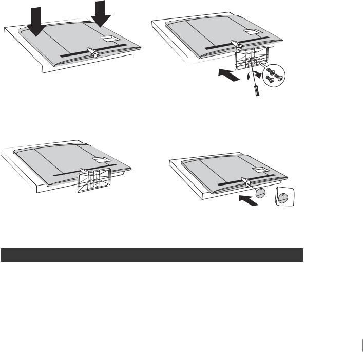
Attaching Your TV to the Table Stand
Your TV comes without the table stand attached so that you can choose to mount your TV either to its table stand or to a wall (wall mount sold separately). If you want to mount your TV to the wall, don’t attach the table stand, and instead, follow the Mounting Your TV to the Wall instructions.
Step 1
Place the plastic bag off the TV and place it on a table or other flat surface. Place the TV set face down on the TV bag.
TV cabinet with Table Stand attached.
Step 2
Take the Table Stand and the three M5 ST-screws.
Attach the Table Stand to the TV with the three M5 ST-screws from the bottom, with a screwdriver.
Note: If you want to mount your TV to the wall, do
not attach the stand, just attach the stand cap to the TV cabinet.
Mounting Your TV to the Wall
To mount your TV to the wall, purchase a VESA wall
|
Models L32HD41/L32HD31R |
Purchase a VESA 200 x100, Size M4 screw |
|
|
|
|
|
The VESA number is the horizontal and vertical measurement of the mounting holes. For example, 200x100 refers to fact that the mounting measurements are 200mm horizontally and 100mm vertically. Follow the directions included with the wall mount to mount the TV to the wall.
Caution: Your wall mount must be able to bear a minimum of five times the TV’s net weight to avoid causing damage.
Connections and Setup Chapter 1 7
Obtain the Signal
The first step in connecting your TV is obtaining the signal. The back panel of your TV allows you to receive analog and/or digital channels by using the ANTENNA/CABLE INPUT.
Before you connect your TV, you have to determine whether you will be using an antenna or a cable service to obtain the signal.
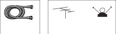
What You Need
Antenna (Rabbit Ears) or Outdoor Antenna with Coaxial Cable
Plug the antenna or coaxial cable from the wall outlet into the ANTENNA/CABLE INPUT on the back of the TV. You are ready to receive off-air local digital and analog channels.
Cable Service
Plug the coaxial cable from the wall outlet into the ANTENNA/CABLE INPUT on the back of the TV. You are ready to receive your cable channels.
Set-Top Box
If you have a set-top box, you may need to call your cable company or satellite service provider. They may recommend special cables to allow you to view digital channels.
What You Need to Know
• Visit www.antennaweb.org for help in deciding what type of antenna to use in order to receive the local digital channels available to you. Enter your location, and the program will list local analog and digital stations available using your antenna.
•When you watch TV, the Channel Banner displays the type of channel currently viewed. A “D” at the bottom of the screen denotes digital channels and an “A” denotes analog channels. For more information on
Channel Banners, see page 20.
OR
COAXIAL CABLE |
|
OUTDOOR OR INDOOR ANTENNA |
|
|
|
8 |
Chapter 1 Connections and Setup |
|
|
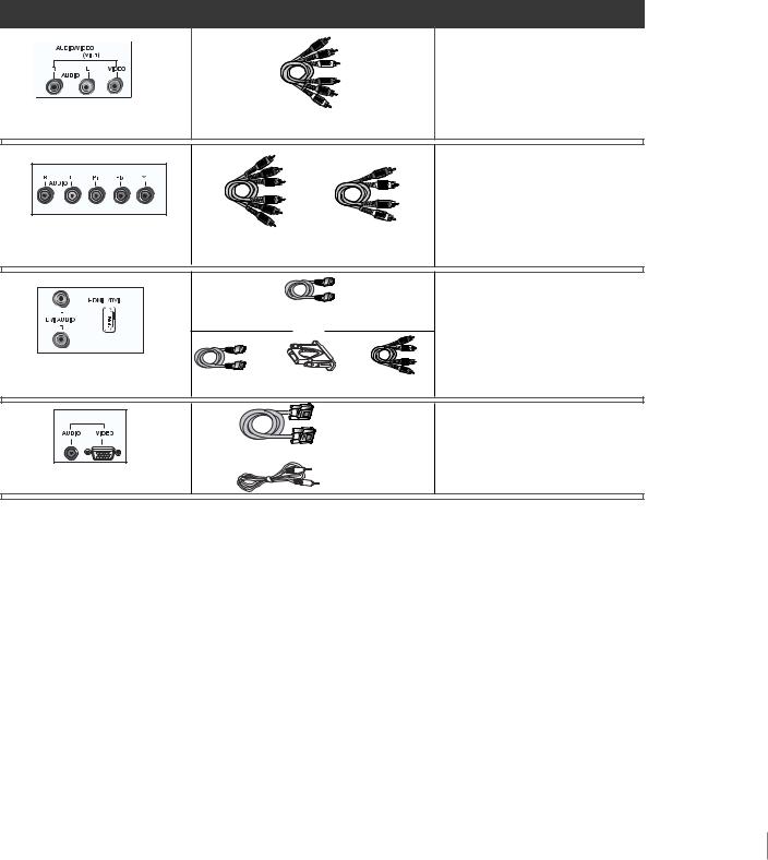
Choose Your Connections
There are several ways to connect components, such as DVD players and setup boxes, to your TV. Please use the following chart to determine which connections are best for you. Proceed to the appropriate pages to connect your components.
Jacks Used |
Cable Needed |
Go to... |
|
INPUT 1 |
|
|
|
|
|
|
page 10 |
Audio R and L |
Video |
Audio/Video |
|
COMPONENT INPUT (CMPT) |
|
|
|
|
|
|
pages 10-11 |
Audio R and L |
Y Pb Pr |
Component Video |
Audio |
|
|
||
1 |
INPUT |
HDMITM |
|
|
|
|
|
|
|
OR |
pages 11-12 |
Audio R and L HDMI/DVI
HDMITM + HDMI/DVI Adapter + Audio
PC INPUT |
VGA |
|
pages 12-13 |
Audio |
VGA |
Audio |
HDMI, the HDMI logo, and High-Definition Multimedia Interface are trademarks or registered trademarks of HDMI Licensing LLC.
|
Input |
Signal Compatability |
|
|
Ant/Cable |
480i, 480p, 720p, 1080i (NTSC, ATSC, and QAM formats) |
|
|
|
|
|
|
Composite Video |
480i |
|
|
|
|
|
|
S-Video |
480i |
|
|
|
|
|
|
Component Video |
480i, 480p, 720p/60Hz, 1080i/60Hz, 1080p |
|
|
|
|
|
|
PC |
VGA, SVGA, XGA |
|
|
|
|
|
|
HDMI |
480i, 480p, 720p/60Hz, 1080i/60Hz, 1080p/60Hz |
|
|
|
|
|
Customer Support
For additional assistance in using your RCA product, please visit the support page at
www.rca.com/tv.
Connections and Setup Chapter 1 9
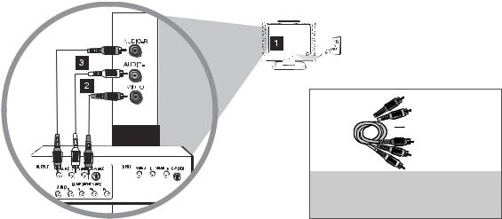
Connecting a Component with Composite Video (Good)
To connect a component with a video output jack, such as a DVD player, follow these steps:
Example: DVD Player
1.Connect the yellow video cable to the (VID 2) VIDEO jack on the side of the TV and to the video output jack on the DVD player.
2.Connect the red and white audio cables to the (VID 2) right and left audio jacks on the side of the TV and to the audio output jacks on the DVD player.
Composite Video Connection
This is an example of a connection using the composite video jack.
AUDIO/VIDEO
INPUT2 (VID2)
Don’t forget:
If necessary, connect antenna or cable to get a picture. Go to page 8 for instructions.
Red
Yellow

 White
White
COMPOSITE VIDEO CABLES ARE COLOR
CODED-YELLOW=VIDEO
RED=RIGHT AUDIO; WHITE=LEFT AUDIO
Connecting a Component with Component Video (Better)
To connect a component that has Y Pb Pr jacks, such as a DVD player, follow these steps:
Example: DVD Player
1.Connect three video cables or special Y Pb Pr cables to the COMPONENT INPUT (CMPT) Y Pb Pr jacks on the back of the TV and to the Y Pb Pr outputs on the DVD player.
2.Connect your red and white audio cables to the COMPONENT INPUT (CMPT) right and left AUDIO jacks on the back of the TV and to the audio output jacks on the DVD player.
10 |
Chapter 1 Connections and Setup |
|
|
Component Video Connection
This is an example of a connection using the component video jacks. Go to page 10 for specific
instructions.
CMPT

 Red
Red


 White
White
AUDIO CABLES ARE COLOR
CODED - RED= RIGHT AUDIO,
WHITE=LEFT AUDIO
Don’t forget:
If necessary, connect antenna or cable to get a picture. Go to page 8 for instructions.
Green


 Red
Red


 Blue
Blue
COMPONENT VIDEO CABLES
(Y Pb Pr) ARE COLOR CODED-
GREEN, BLUE AND RED
Connecting a Component with HDMI (Best)
High-Definition Multimedia Interface (HDMI) technology is an uncompressed digital connection that carries both video and audio data by way of an integrated mini-plug cable. Since HDMI technology is based on Digital Visual Interface (DVI), the jack on the back of your TV is also compatible with components that have a DVI output jack.
Example: Set-top box with HDMI jack:
1.Connect an HDMI cable to the HDMI INPUT 2 jack or the HDMI/DVI INPUT 1 jack on the back of the TV and to the HDMI output jack on the back of the set-top box.
Example: Set-top box with DVI jack:
To connect an HDMI cable and an HDMI/DVI adapter:
1.Connect an HDMI cable to the HDMI/DVI INPUT 1 jack on the back of the TV.
2.Attach an HDMI/DVI adapter to the end of the HDMI cable; then connect the adapter to the DVI output jack on the set-top box.
3.Since you’re using an HDMI/DVI adapter, you need to connect separate audio cables to the DVI AUDIO INPUT right and left DVI AUDIO jacks on the back of the TV and to the right and left audio jacks on the back of the set-top box.
Connections and Setup Chapter 1 11
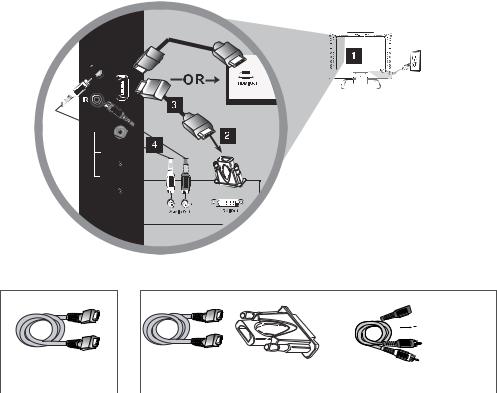
HDMI/DVI Connection (Best)
This is an example of a connection using the HDMI/DVI INPUT 1 jack. Go to page 11 for specific instructions.
Don’t forget:
If necessary, connect antenna or cable to get a picture. Go to page 8 for instructions.
HDMI/DVI 
 INPUT 1
AUDIO
PC INPUT
VIDEO

 Red
Red


 White
White
OR
HDMI Cable |
|
HDMI Cable + HDMI/DVI Adapter + |
Audio cables are color coded |
|
|
|
Red=right audio; white=left audio |
Connecting a PC Component
To connect a personal computer and use your TV as a monitor, follow these steps:
1.Connect one end of a 15-pin monitor cable to the PC VIDEO jack on the TV and the other end to the PC's video output jack.
Note: If your PC's video output isn't 15-pin, you'll need an adapter that can connect to a 15-pin monitor cable.
2.Connect a 3.5mm stereo mini-pin audio cable (sometimes referred to as 1/8" stereo mini-pin) to the PC AUDIO jack on the back of the TV and the other end to the audio output jack on the PC.
12 |
Chapter 1 Connections and Setup |
|
|
 Loading...