


LCD Television
User’s Guide
Commercial Television
J22C760 J26C700
J32C750 J42C750
Changing Entertainment. Again.
Important Information
CAUTION
RISK OF ELECTRIC SHOCK
DO NOT OPEN
CAUTION:
TO REDUCE THE RISK OF ELECTRIC SHOCK DO NOT REMOVE COVER (OR BACK). NO USER SERVICEABLE PARTS INSIDE. REFER TO QUALIFIED SERVICE PERSONNEL.
The lightning flash with arrowhead symbol, within an equilateral triangle, is intended to alert the user to the presence of uninsulated “dangerous voltage” within the product’s enclosure that may be of sufficient magnitude to constitute a risk of electric shock to persons.
The exclamation point within an equilateral triangle is intended to alert the user to the presence of important operating and maintenance (servicing) instructions in the literature accompanying the appliance.
WARNING
TO PREVENT FIRE OR SHOCK HAZARDS, DO NOT EXPOSE THIS PRODUCT TO RAIN OR MOISTURE.
Product Registration
Please fill out the product registration card (packed separately) and return it immediately. For US customers: Your RCA Consumer Electronics product may also be registered at http://service.rcacommercialtv.com. Registering this product allows us to contact you if needed.
Product Information
Keep your sales receipt to obtain warranty parts and service and for proof of purchase. Attach it here and record the serial and model numbers in case you need them. These numbers are located on the product.
Model No.
Serial No.
Purchase Date:
Dealer/Address/Phone:
NOTE TO CABLE TV INSTALLER
This reminder is provided to call the CATV system installer’s attention to Article 820-40 of the National Electric Code (U.S.A.). The code provides guidelines for proper grounding and, in particular, specifies that the cable ground shall be connected to the grounding system of the building, as close to the point of the cable entry as practical.
2

Important Information
CAUTION
Do not attempt to modify this product in any way without written authorization from RCA. Unauthorized modification could void the user’s authority to operate this product.
CAUTION
THESE SERVICING INSTRUCTIONS ARE FOR USE BY QUALIFIED SERVICE PERSONNEL ONLY. TO REDUCE THE RISK OF ELECTRIC SHOCK, DO NOT PERFORM ANY SERVICING OTHER THAN THAT CONTAINED IN THE OPERATING INSTRUCTIONS UNLESS YOU ARE QUALIFIED TO DO SO.
WARNING
Apparatus shall not be exposed to dripping or splashing and no objects filled with liquids, such as vases, shall not be placed on the apparatus.
CAUTION
When used outside of U.S., other power supply cords may be used if the cord is approved by the local regulating agency.
CLEANING AND DISINFECTION
Clean the exterior of this television by removing dust with a lint-free cloth.
CAUTION: To avoid damage to the surface of the television, do not use abrasive or chemical cleaning agents.
This apparatus with class I construction shall be connected to a main socket outlet with a protective earthing connection.
3

Important Information
DISCONNECTING DEVICE FROM MAINS
Main plug is the disconnecting device. The plug must remain readily operable.
IMPORTANT SAFEGUARDS FOR YOU AND YOUR NEW PRODUCT
YOUR PRODUCT HAS BEEN MANUFACTURED AND TESTED WITH YOUR SAFETY IN MIND. HOWEVER, IMPROPER USE CAN RESULT IN POTENTIAL ELECTRICAL SHOCK OR FIRE HAZARDS. TO AVOID DEFEATING THE SAFEGUARDS THAT HAVE BEEN BUILT INTO YOUR NEW PRODUCT, PLEASE READ AND OBSERVE THE FOLLOWING SAFETY POINTS WHEN INSTALLING AND USING YOUR NEW PRODUCT, AND SAVE THEM FOR FUTURE REFERENCE. OBSERVING THE SIMPLE PRECAUTIONS DISCUSSED IN THIS MANUAL CAN HELP YOU GET MANY YEARS OF ENJOYMENT AND SAFE OPERATION THAT ARE BUILT INTO YOUR NEW PRODUCT.
Note
-If the TV feels cold to the touch, there may be a small “flicker” when it is turned on. This is normal, there is nothing wrong with the TV.
-Some minute dot defects may be visible on the screen, appearing as tiny red, green, or blue spots. However, they have no adverse effect on the TVs performance.
-Avoid touching the LCD screen or holding your finger(s) against it for long periods of time. Doing so may produce some temporary distortion effects on the screen.
REGULATORY INFORMATION
This equipment has been tested and found to comply with the limits for a Class B digital device, pursuant to Part 15 of the FCC Rules.
These limits are designed to provide reasonable protection against harmful interference when the equipment is operated in a residential installation.
This equipment generates, uses and can radiate radio frequency energy and, if not installed and used in accordance with the instruction manual, may cause harmful interference to radio communications. However, there is no guarantee that interference will not occur in a particular installation.
If this equipment does cause harmful interference to radio or television reception, which can be determined by turning the equipment off and on, the user is encouraged to try to correct the interference by one or more of the following measures:
•Reorient or relocate the receiving antenna.
•Increase the separation between the equipment and receiver.
•Connect the equipment into an outlet on a circuit different from that to which the receiver is connected.
•Consult the dealer or an experienced radio/TV technician for help.
CAUTION
Changes or modifications not expressly approved by the party responsible for compliance could void the user’s authority to operate the equipment.
THE PARTY RESPONSIBLE FOR PRODUCT COMPLIANCE
(RCA Commercial Electronics)
(TELEPHONE NO : 800-RCA-2161)
4
IMPORTANT SAFETY INSTRUCTIONS Read before operating equipment
1.Read these instructions.
2.Keep these instructions.
3.Heed all warnings.
4.Follow all instructions.
5.Do not use this apparatus near water.
6.Clean only with dry cloth.
7.Do not block any ventilation openings. Install in accordance with the manufacturer’s instructions.
8.Do not install near any heat sources such as radiators, heat registers, stoves, or other apparatus (including amplifiers) that produce heat.
9.Do not defeat the safety purpose of the polarized or grounding-type plug. A polarized plug has two blades with one wider than the other. A grounding type plug has two blades and a third grounding prong. The wide blade or the third prong is provided for your safety. If the provided plug does not fit into your outlet, consult an electrician for replacement of the obsolete outlet.
10.Protect the power cord from being walked on or pinched particularly at plugs, convenience receptacles, and the point where they exit from the apparatus.
11.Only use attachments/accessories specified by the manufacturer.
12.Use only with the cart, stand, tri-
pod, bracket, or table specified by the manufacturer, or sold with the apparatus. When a cart is
used, use caution when moving  the cart/apparatus combination to
avoid injury from tip-over.
13.Unplug this apparatus during lightning storms or when unused for long periods of time.
14.Refer all servicing to qualified service personnel. Servicing is required when the apparatus has been damaged in any way, such as powersupply cord or plug is damaged, liquid has been spilled or objects have fallen into the apparatus, the apparatus has been exposed to rain or moisture, does not operate normally, or has been dropped.
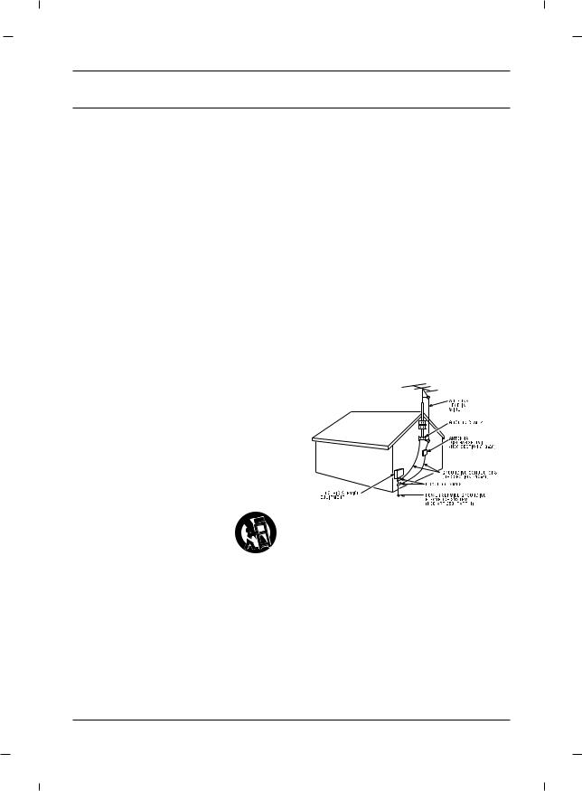
15.If an outside antenna or cable system is connected to the product, be sure the antenna or cable system is grounded so as to provide some protection against voltage surges and built-up static charges. Section 810 of the National Electrical Code, ANSI/NFPA No. 70-1984 (Section 54 of Canadian Electrical Code, Part 1) provides information with respect to proper grounding of the mast and supporting structure, grounding of the leadin wire to an antenna-discharge unit, size of grounding conductors, location of antenna-dis- charge unit, connection to grounding electrodes, and requirements for the grounding electrode. See following example.
Note
-The lamp in this product contains mercury. Please dispose of in accordance with local, state, or federal laws.
5

Table of Contents
Important Information .............................................. |
2 |
IMPORTANT SAFETY INSTRUCTIONS ........................ |
5 |
Chapter 1: Connections and Setup |
|
Things to Consider Before You Connect .................. |
7 |
Protect Against Power Surges ........................ |
7 |
Protect Devices from Overheating.................. |
7 |
Position Cables Properly to Avoid Audio |
|
Interference ...................................................... |
7 |
Use Indirect Light ............................................ |
7 |
Remote Control ................................................ |
7 |
Check Supplied Parts........................................ |
7 |
Controls And Connectors .......................................... |
8 |
Front Panel - J22C760 ...................................... |
8 |
Rear Panel - J22C760........................................ |
9 |
Front Panel - J26C700 .................................... |
10 |
Rear Panel - J26C700...................................... |
11 |
Front Panel - J32C750 .................................... |
12 |
Rear Panel - J32C750...................................... |
13 |
Front Panel - J42C750 .................................... |
14 |
Rear Panel - J42C750...................................... |
15 |
Connections .............................................................. |
16 |
Wall mount Installation ................................ |
16 |
Desktop Pedestal Installation ........................ |
16 |
Parts for stand assembly ................................ |
17 |
Stand Installation .......................................... |
19 |
Antenna Connection...................................... |
22 |
VCR Connection.............................................. |
23 |
DVD Connection ............................................ |
25 |
HDSTB Connection ........................................ |
26 |
External A/V Source........................................ |
29 |
Digital Audio Out .......................................... |
30 |
PC Connection ................................................ |
31 |
Resolution ...................................................... |
33 |
USB in Setup .................................................. |
33 |
Chapter 2: Using the Remote Control |
|
Basic(User) Remote ........................................ |
34 |
Master(Installer) Remote .............................. |
35 |
Put Batteries in the Remote .......................... |
35 |
Chapter 3: Using USB Clone Tool |
|
USB Cloner Out-looking ................................ |
36 |
Errors Table .................................................... |
36 |
Learning Connection .................................... |
37 |
Teaching Connection...................................... |
39 |
Chapter 4: Basic Operation |
|
Plug in the TV ................................................ |
40 |
Turn on the TV................................................ |
40 |
Channel Scan .................................................. |
40 |
Channel Selection .......................................... |
40 |
Volume Adjustment ...................................... |
40 |
Sound Mute .................................................... |
40 |
Source Selection ............................................ |
41 |
Language Selection........................................ |
41 |
Chapter 5: Commercial Interface Menus |
|
Commercial Interface Menus .................................. |
42 |
Chapter 6: Using the TV's Features |
|
On Screen Menus .................................................... |
45 |
Setting up the TV Channel .................................... |
46 |
Auto Scan........................................................ |
46 |
Add / Delete a Channel.................................. |
47 |
Picture Controls ........................................................ |
48 |
Adjusting The Picture Controls .................... |
48 |
Manual Picture Controls ................................ |
49 |
Gamma............................................................ |
50 |
Color Temperature ........................................ |
51 |
Reset Picture Mode ........................................ |
52 |
Advanced Video ...................................................... |
53 |
Dynamic Noise Reduction .............................. |
53 |
CTI (Color Transient Intensity) ...................... |
54 |
Flesh Tone ...................................................... |
54 |
Adaptive Luma Control.................................. |
55 |
Blue Mute ...................................................... |
55 |
Back Light ...................................................... |
56 |
Screen Mode .................................................. |
57 |
Sound Controls ........................................................ |
58 |
Adjusting The Sound Controls ...................... |
58 |
Manual Sound Controls ................................ |
59 |
Sound Surround ............................................ |
60 |
Equalizer ........................................................ |
60 |
Digital Output ................................................ |
61 |
Stereo/SAP Broadcast Setup .......................... |
62 |
Audio Language ............................................ |
62 |
Time Setting ............................................................ |
63 |
Time Zone Settings ........................................ |
63 |
Auto Time Settings ........................................ |
64 |
Manual Time Settings .................................... |
65 |
Auto On /Off Time Settings .......................... |
66 |
Sleep Timer .................................................... |
67 |
Captions .................................................................... |
68 |
Closed Caption - Analog................................ |
68 |
Closed Caption - Digital ................................ |
69 |
Digital Closed Caption Options .................... |
70 |
Reset ........................................................................ |
71 |
Reset Default .................................................. |
71 |
Parental Control ...................................................... |
72 |
Entering your password ................................ |
72 |
Set Password .................................................. |
72 |
Ratings - Enable / Disable .............................. |
73 |
TV Ratings for USA ........................................ |
74 |
Movie Ratings ................................................ |
76 |
English TV Ratings for Canada ...................... |
77 |
French TV Ratings for Canada ...................... |
78 |
Downloadable Rating .................................... |
79 |
Block Unrated ................................................ |
80 |
Clean All.......................................................... |
80 |
Setting the PC Mode................................................ |
81 |
Automatic Screen Adjustment ...................... |
81 |
Manual Screen Adjustment .......................... |
82 |
USB Functions .......................................................... |
83 |
Picture Function ............................................ |
83 |
Music Function .............................................. |
84 |
Specification ............................................................ |
85 |
Chapter 7: Other Information |
|
Troubleshooting ...................................................... |
89 |
Limited Warranty .................................................... |
90 |
Care and Cleaning .................................................... |
91 |
CHILD SAFETY .......................................................... |
92 |
6

Chapter 1: Connections and Setup
"User must use shielded signal interface cables with ferrite cores to maintain standard compliance for the product"
Things to Consider Before You Connect
Protect Against Power Surges
•Connect all devices before you plug any of their power cords into the wall outlet or power strip. NEVER plug your TV into an outlet that is controlled by a wall switch.
•Turn off the TV and/or device(s) before you connect or disconnect any cables.
•Make sure all antennas and cables are properly grounded. Refer to the Important Safety Instructions at the beginning of the User's Guide.
Protect Devices from Overheating
•Don’t block ventilation holes on any of the devices. Arrange the devices so that air can circulate freely.
•Don’t stack devices.
•If you place devices in a stand, make sure you allow adequate ventilation.
•If you connect an audio receiver or amplifier, place it on the top shelf so the heated air from it won’t flow around other devices.
Position Cables Properly to Avoid Audio Interference
•Insert each cable firmly into the designated jack.
•If you place devices above the TV, route all cables down the side of the back of the TV instead of straight down the middle.
•If your antenna uses 300-ohm twin lead cables, do not coil the cables. Also, keep the twin lead cables away from audio/video cables.
Use Indirect Light
Don’t place the TV where sunlight or room lighting will be directed toward the screen. Use soft or indirect lighting.
Remote Control
You will need a master remote or USB Cloner to set up the TV. Contact your RCA Commercial Distributor to purchase these.
Check Supplied Parts
Check that the following parts were packed with your product.
Power Cord |
|
Owner’s Manual |
Stand Base |
Stand Body |
|
|
|
(Optional) |
(Optional) |
|
|
|
Note
-If you need to replace your remote, call 800-RCA-2161. A shipping and handling fee, and the appropriate sales tax, will be charged upon ordering. Have your Visa, MasterCard, or Discover Card ready.
-Stand Base, Stand Body images shown may differ from your TV.
Chapter 1 |
Graphics contained within this publication are for representation only. |
7 |

Chapter 1: Connections and Setup
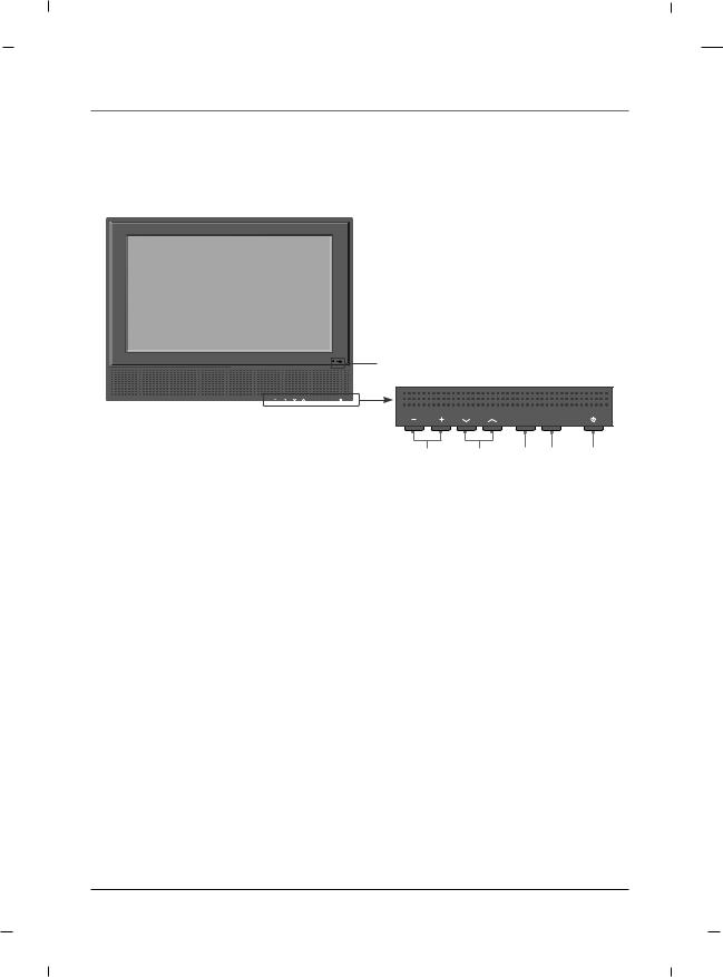
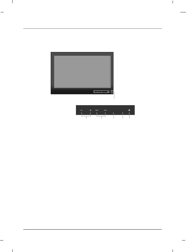
Front Panel - J22C760
VOL |
CH |
SOURCE MENU |
6 1 2 3 4 5
1.VOL- / VOL+
Adjusts sound level and menu settings.
2.CH  / CH
/ CH 
Select a channel.
3.SOURCE
Selects the TV, AV1, AV2, YPbPr, VGA, HDMI or USB mode.
4.MENU
Display on screen menus.
5.POWER
Switches the set on or off.
6.Power Indicator
Illuminates to bright blue when the TV is on. When the TV is powered off, this LED is also off.
Remote control sensor
Accepts the IR signal of remote controller.
Note
- Image shown may differ from your TV.
8 |
Chapter 1 |
Chapter 1: Connections and Setup
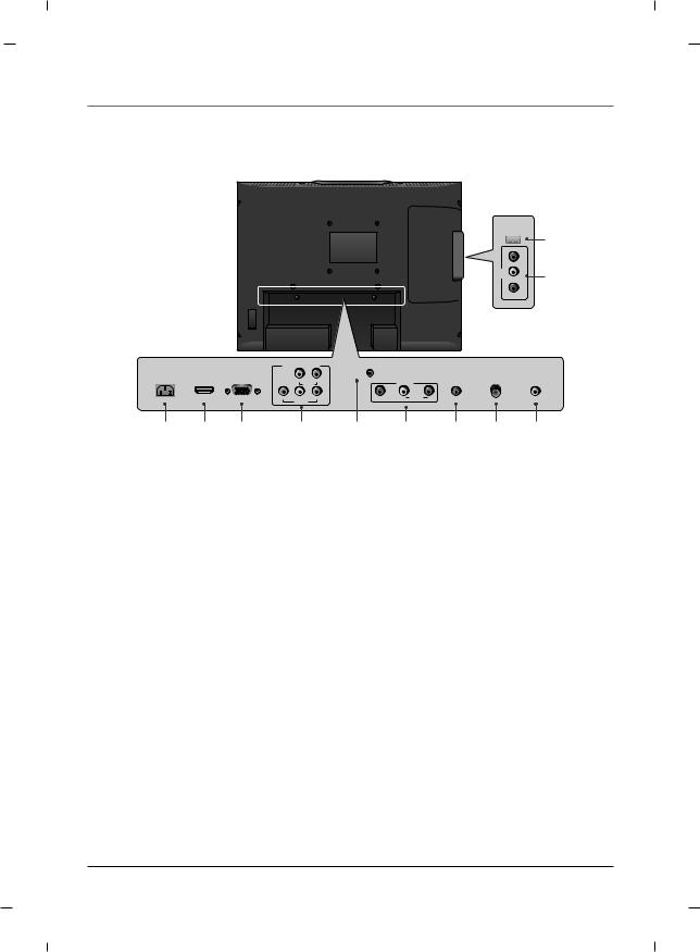
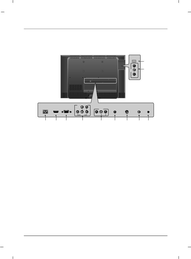
Rear Panel - J22C760
USB IN 
AV2 |
L-AUDIO-R |
|
VIDEO |
10
11
|
|
COMPONENT IN |
|
|
|
|
|
||
AC IN |
HDMI/DVI |
RGB IN |
|
|
SERVICE |
|
AUDIO IN |
ANTENNA/ |
DIGITAL AUDIO |
|
|
|
|
||||||
|
IN |
(PC) |
L |
R |
|
AV1 |
(RGB/DVI) |
CABLE IN |
OUT(COAXIAL) |
|
|
|
AUDIO |
|
|
|
|
|
|
|
|
Y |
Pb |
Pr |
VIDEO |
L AUDIO R |
|
|
|
|
|
|
VIDEO |
|
|
|
|
|
|
1 |
2 |
3 |
4 |
1.AC IN
This TV operates on AC power.
2.HDMI/DVI IN
Connect to the HDMI jack on devices with an HDMI output.
This input can also be used as a DVI connection with separate analog audio inputs.
3.RGB IN (PC)
Connect to the video output jack on your PC.
4.COMPONENT IN (YPbPr)
Video/Audio inputs for Component.
5.SERVICE
Used by clone device to learn settings in TV.
6.AV1
Connects to your Audio/Video devices using a composite (Yellow/Red/White) cable.
5 |
6 |
7 |
8 |
9 |
7.AUDIO IN (RGB/DVI)
Connect to the audio output jack on your PC.
8.ANTENNA/CABLE IN
Connect to your antenna or cable box for TV signal.
9.DIGITAL AUDIO OUT(COAXIAL)
Connect digital audio to various types of equipment.
10.USB IN
USB device interface.
11.AV2
Connects to your Audio/Video devices using a composite (Yellow/Red/White) cable.
Note
- Image shown may differ from your TV.
Chapter 1 |
9 |
Chapter 1: Connections and Setup
Front Panel - J26C700
|
|
|
6 |
VOL |
CH |
SOURCE |
MENU |
VOL |
CH |
SOURCE MENU |
1 2 3 4 5
1.VOL- / VOL+
Adjusts sound level and menu settings.
2.CH  / CH
/ CH 
Select a channel.
3.SOURCE
Selects the TV, AV1, AV2, YPbPr, VGA, HDMI or USB mode.
4.MENU
Display on screen menus.
5.POWER
Switches the set on or off.
6.Power Indicator
Illuminates to bright blue when the TV is on. When the TV is powered off, this LED is also off.
Remote control sensor
Accepts the IR signal of remote controller.
Note
- Image shown may differ from your TV.
10 |
Chapter 1 |
Chapter 1: Connections and Setup
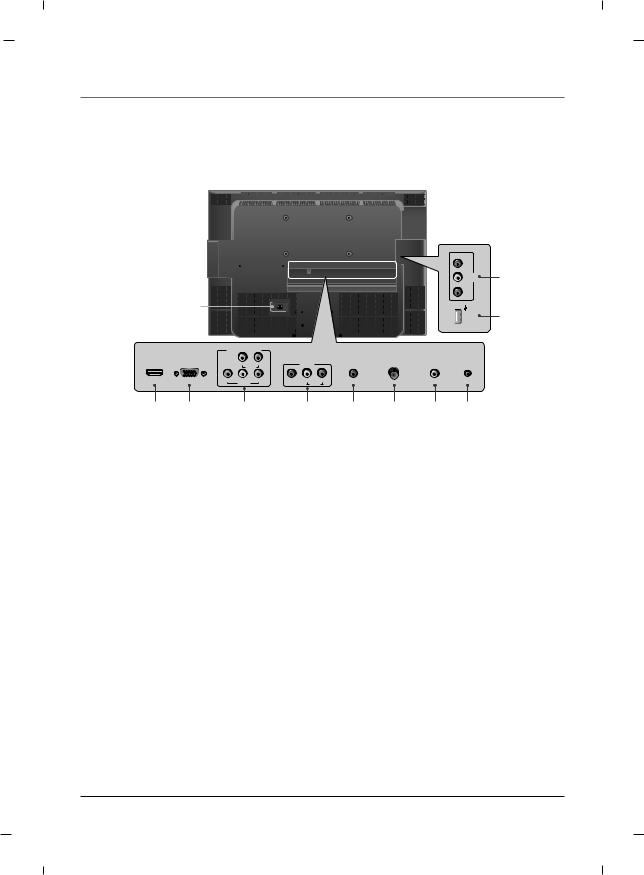
Rear Panel - J26C700
10
11
USB IN 
|
VIDEO |
AV2 |
AUDIO - L |
|
R - |
|
|
COMPONENT IN |
|
|
|
|
|
||
AC IN |
HDMI/DVI |
RGB IN |
|
|
|
|
AUDIO IN |
ANTENNA/ |
DIGITAL AUDIO |
|
IN |
(PC) |
L |
R |
|
AV1 |
(RGB/DVI) |
CABLE IN |
OUT(COAXIAL) SERVICE |
|
|
|
AUDIO |
|
|
|
|
|
|
|
|
Y |
Pb |
Pr |
VIDEO |
L |
R |
|
|
|
|
|
VIDEO |
|
|
|
AUDIO |
|
|
1 |
2 |
3 |
4 |
1.AC IN
This TV operates on AC power.
2.HDMI/DVI IN
Connect to the HDMI jack on devices with an HDMI output.
This input can also be used as a DVI connection with separate analog audio inputs.
3.RGB IN (PC)
Connect to the video output jack on your PC.
4.COMPONENT IN (YPbPr)
Video/Audio inputs for Component.
5.AV1
Connects to your Audio/Video devices using a composite (Yellow/Red/White) cable.
5 |
6 |
7 |
8 |
9 |
6.AUDIO IN (RGB/DVI)
Connect to the audio output jack on your PC.
7.ANTENNA/CABLE IN
Connect to your antenna or cable box for TV signal.
8.DIGITAL AUDIO OUT(COAXIAL)
Connect digital audio to various types of equipment.
9.SERVICE
Used by clone device to learn settings in TV.
10.USB IN
USB device interface.
11.AV2
Connects to your Audio/Video devices using a composite (Yellow/Red/White) cable.
Note
- Image shown may differ from your TV.
Chapter 1 |
11 |

Chapter 1: Connections and Setup
Front Panel - J32C750
VOL |
CH |
SOURCE MENU |
|
|
|
|
6 |
|
|
VOL |
CH |
SOURCE |
MENU |
|
1 |
2 |
3 |
4 |
5 |
1.VOL- / VOL+
Adjusts sound level and menu settings.
2.CH  / CH
/ CH 
Select a channel.
3.SOURCE
Selects the TV, AV1, AV2, YPbPr, VGA, HDMI or USB mode.
4.MENU
Display on screen menus.
5.POWER
Switches the set on or off.
6.Power Indicator
Illuminates to bright blue when the TV is on. When the TV is powered off, this LED is also off.
Remote control sensor
Accepts the IR signal of remote controller.
Note
- Image shown may differ from your TV.
12 |
Chapter 1 |
Chapter 1: Connections and Setup
Rear Panel - J32C750
USB IN 
AV2 |
L - AUDIO - R |
|
VIDEO |
10
11
|
|
COMPONENT IN |
|
|
|
|
|
||
AC IN |
HDMI/DVI |
RGB IN |
|
|
|
|
AUDIO IN |
ANTENNA/ |
DIGITAL AUDIO |
|
IN |
(PC) |
L |
R |
|
AV IN |
(RGB/DVI) |
CABLE IN |
OUT(COAXIAL) SERVICE |
|
|
|
AUDIO |
|
|
|
|
|
|
|
|
Y |
Pb |
Pr |
VIDEO |
L |
R |
|
|
|
|
|
VIDEO |
|
|
AUDIO |
|
|
|
1 2 3 4 5 6 7 8 9
1.AC IN
This TV operates on AC power.
2.HDMI/DVI IN
Connect to the HDMI jack on devices with an HDMI output.
This input can also be used as a DVI connection with separate analog audio inputs.
3.RGB IN (PC)
Connect to the video output jack on your PC.
4.COMPONENT IN (YPbPr)
Video/Audio inputs for Component.
5.AV1
Connects to your Audio/Video devices using a composite (Yellow/Red/White) cable.
6.AUDIO IN (RGB/DVI)
Connect to the audio output jack on your PC.
7.ANTENNA/CABLE IN
Connect to your antenna or cable box for TV signal.
8.DIGITAL AUDIO OUT(COAXIAL)
Connect digital audio to various types of equipment.
9.SERVICE
Used by clone device to learn settings in TV.
10.USB IN
USB device interface.
11.AV2
Connects to your Audio/Video devices using a composite (Yellow/Red/White) cable.
Note
- Image shown may differ from your TV.
Chapter 1 |
13 |
Chapter 1: Connections and Setup
Front Panel - J42C750
VOL |
CH SOURCE MENU |
|
|
|
|
|
6 |
|
|
VOL |
CH |
SOURCE |
MENU |
|
1 |
2 |
3 |
4 |
5 |
1.VOL- / VOL+
Adjusts sound level and menu settings.
2.CH  / CH
/ CH 
Select a channel.
3.SOURCE
Selects the TV, AV1, AV2, YPbPr, VGA, HDMI or USB mode.
4.MENU
Display on screen menus.
5.POWER
Switches the set on or off.
6.Power Indicator
Illuminates to bright blue when the TV is on. When the TV is powered off, this LED is also off.
Remote control sensor
Accepts the IR signal of remote controller.
Note
- Image shown may differ from your TV.
14 |
Chapter 1 |
Chapter 1: Connections and Setup
Rear Panel - J42C750
L - AUDIO - R |
AV2 |
VIDEO |
|
USB IN |
|
|
COMPONENT IN |
|
|
|
|
|
|
||
HDMI/DVI |
RGB IN |
|
|
|
|
AUDIO IN |
ANTENNA/ |
DIGITAL AUDIO |
|
IN |
(PC) |
L |
R |
|
AV1 |
(RGB/DVI) |
CABLE IN |
OUT(COAXIAL) |
SERVICE |
|
|
AUDIO |
|
|
|
|
|
|
|
|
Y |
Pb |
Pr |
VIDEO |
L |
R |
|
|
|
|
|
VIDEO |
|
|
|
AUDIO |
|
|
|
11
10
2 |
3 |
4 |
5 |
6 |
7 |
8 |
9 |
1.AC IN
This TV operates on AC power.
2.HDMI/DVI IN
Connect to the HDMI jack on devices with an HDMI output.
This input can also be used as a DVI connection with separate analog audio inputs.
3.RGB IN (PC)
Connect to the video output jack on your PC.
4.COMPONENT IN (YPbPr)
Video/Audio inputs for Component.
5.AV1
Connects to your Audio/Video devices using a composite (Yellow/Red/White) cable.
6.AUDIO IN (RGB/DVI)
Connect to the audio output jack on your PC.
7.ANTENNA/CABLE IN
Connect to your antenna or cable box for TV signal.
8.DIGITAL AUDIO OUT(COAXIAL)
Connect digital audio to various types of equipment.
9.SERVICE
Used by clone device to learn settings in TV.
10.USB IN
USB device interface.
11.AV2
Connects to your Audio/Video devices using a composite (Yellow/Red/White) cable.
Note
- Image shown may differ from your TV.
Chapter 1 |
15 |
Chapter 1: Connections and Setup
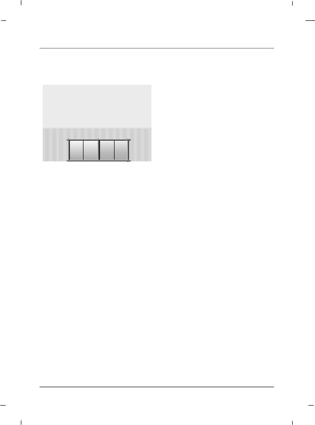
Wall mount Installation
|
4 inches |
|
4 inches |
4 inches |
4 inches |
|
4 inches |
The set can be installed on a wall as shown above.
For proper ventilation, allow a clearance of 4 inches on all four sides from the wall.
Detailed instructions are available from your dealer, refer to the optional Wall Mounting Bracket Installation and Setup Guide. (Wall Mount Sold Separately)
Note
- This Television should be installed by a Qualified Service Personnel.
Desktop Pedestal Installation
|
4 inches |
|
4 inche |
4 inches |
4 inches |
The set can be mounted on a desk as shown above.
For proper ventilation, allow a clearance of 4 inches on each side from the wall.
Detailed instructions are available from your dealer.
Note
- Image shown may differ from your TV.
16 |
Chapter 1 |
Chapter 1: Connections and Setup
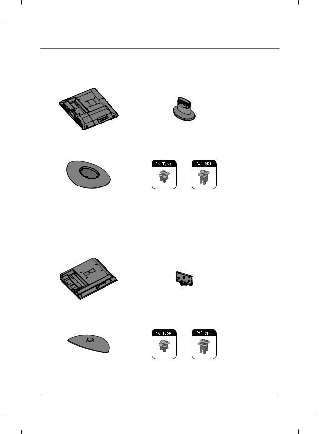
Parts for stand assembly - 22 inch
TV |
Stand Body |
|
|
Stand Base |
4 - A type bolts |
|
4 - B type bolts |
|
Parts for stand assembly - 26 inch
TV |
|
Stand Body |
|
|
|
Stand Base |
|
4 - A type bolts |
|
|
4 - B type bolts |
|
||
|
|
|
Chapter 1 |
17 |
Chapter 1: Connections and Setup
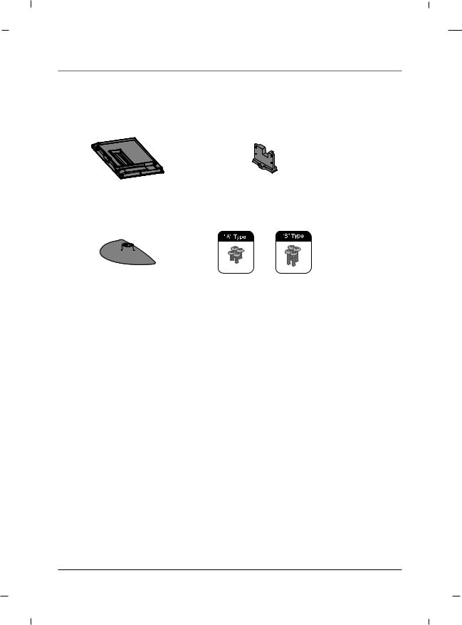
Parts for stand assembly - 32/42 inches
TV |
Stand Body |
Stand Base |
4 - A type bolts |
|
4 - B type bolts |
18 |
Chapter 1 |
Chapter 1: Connections and Setup
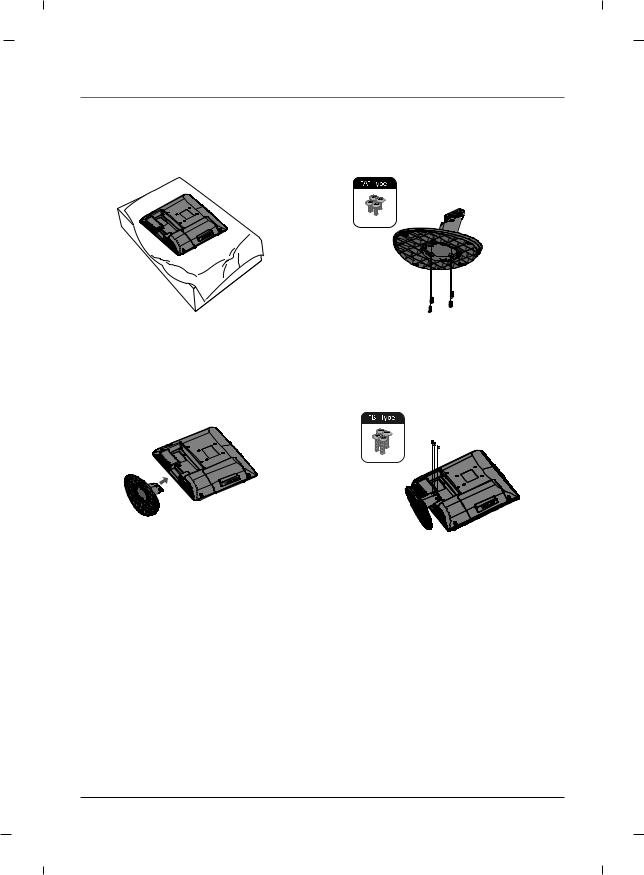
Stand Installation - 22 inch
1.Carefully place the product screen side down on a cushioned surface that will protect the product and screen from damage.
3.Assemble the product stand with the product as shown.
Note
- Image shown may differ from your TV.

 Stand body
 Stand base
2.Using the screws provided assemble the stand body with the stand base as shown.
4.Install the 4 bolts securely, in the back of the product in the holes provided.
Chapter 1 |
19 |
Chapter 1: Connections and Setup
Stand Installation - 26 inch
1.Carefully place the product screen side down on a cushioned surface that will protect the product and screen from damage.
3.Assemble the product stand with the product as shown.
Note
- Image shown may differ from your TV.
Stand body
Stand base
2.Using the screws provided assemble the stand body with the stand base as shown.
4.Install the 4 bolts securely, in the back of the product in the holes provided.
20 |
Chapter 1 |
Chapter 1: Connections and Setup
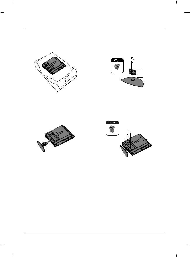
Stand Installation - 32/42 inches
Stand body
 Stand base
1.Carefully place the product screen side down on a cushioned surface that will protect the product and screen from damage.
3.Remove the included stand cover from the product.
5.Install the 4 bolts securely, in the back of the product in the holes provided.
Note
2.Using the screws provided assemble the stand body with the stand base as shown.
4.Assemble the product stand with the product as shown.
-Image shown may differ from your TV.
-When mounting TV on the wall, install the included Stand Cover over the hole for the stand. Press the Stand Cover into the TV until you hear it click.
Chapter 1 |
21 |

Chapter 1: Connections and Setup
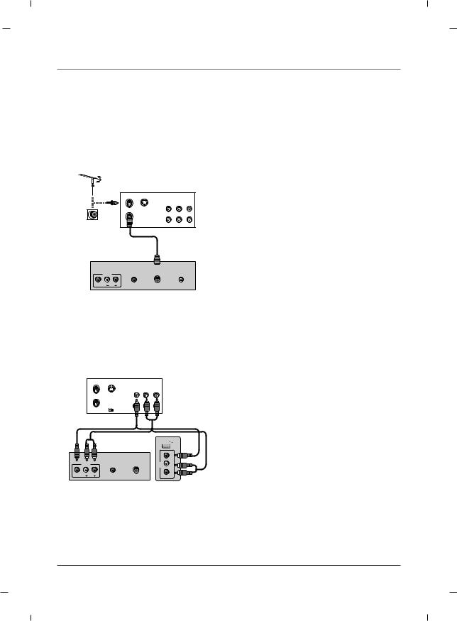
Antenna Connection
Multi-family Dwellings/ Apartments
(Connect to wall antenna socket) |
|
Rear panel of the set |
|
|
|
|
|
|
AUDIO IN |
ANTENNA/ |
DIGITAL AUDIO |
AV1 |
(RGB/DVI) |
CABLE IN |
OUT(COAXIAL) |
VIDEO L |
R |
|
|
|
AUDIO |
|
|
Wall Antenna Socket
RF Coaxial Wire (75 ohm)
Turn clockwise to tighten.
VHF
UHF
Outdoor Antenna
Be careful not to bend the bronze wire when connecting to an antenna port.
* Separately purchase a RF Coaxial Wire(75 ohm)
Single-family Dwellings /Houses
(Connect to wall jack for outdoor antenna)
Rear panel of the set
Note
-To improve the picture quality in a poor signal area, please purchase a signal amplifier and install properly.
-If the antenna is not installed properly, contact your dealer for assistance.
VHF UHF
Signal
Amplifier
|
|
AUDIO IN |
ANTENNA/ |
DIGITAL AUDIO |
|
AV1 |
(RGB/DVI) |
CABLE IN |
OUT(COAXIAL) |
VIDEO |
L |
R |
|
|
|
|
AUDIO |
|
|
22 |
Chapter 1 |
Chapter 1: Connections and Setup
VCR Connection
- To avoid picture noise (interference), leave an adequate distance between the TV and the VCR.
A When connecting with an antenna
VCR
ANT IN |
|
|
(R) AUDIO (L) VIDEO |
ANT OUT S-VIDEO |
OUT |
|
IN |
|
|
AUDIO IN |
ANTENNA/ |
DIGITAL AUDIO |
|
AV1 |
(RGB/DVI) |
CABLE IN |
OUT(COAXIAL) |
VIDEO |
L |
R |
|
|
|
|
AUDIO |
|
|
Rear panel of the set
1.Connect the Antenna out socket of the VCR to the Antenna input socket on the TV.
2.Power up the VCR and Television.
3.Tune the TV to the channel output by the VCR. (typically ch.3 or 4.)
4.Refer to the VCR manual for operating instructions.
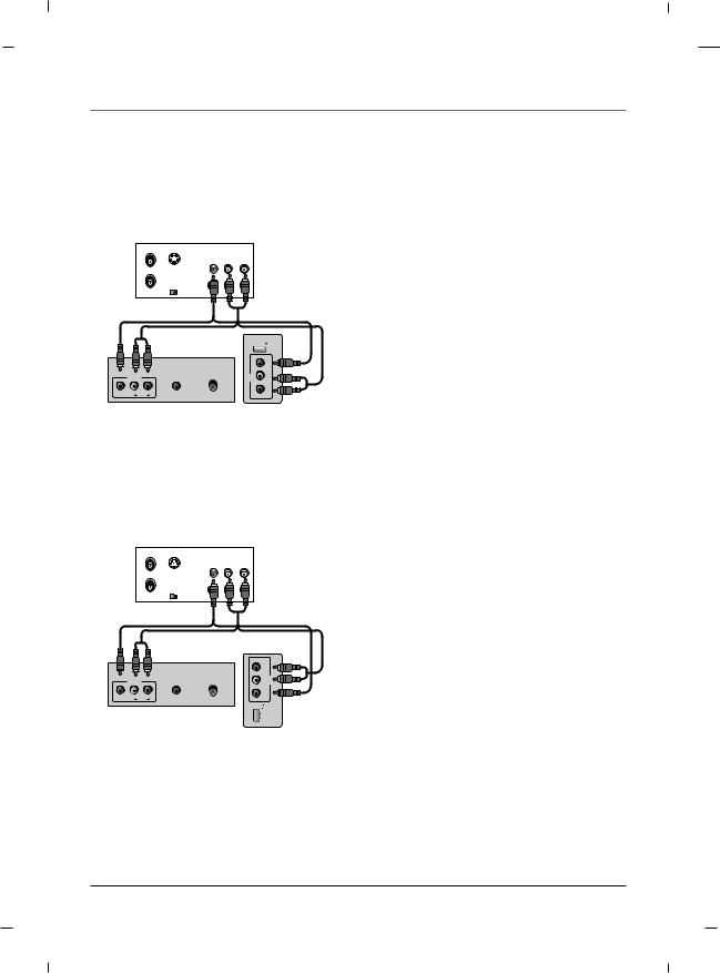
A When connecting with an RCA cable - 22/26 inches
|
|
|
VCR |
ANT IN |
|
|
|
|
|
VIDEO |
(L) AUDIO (R) |
ANT OUT |
S-VIDEO |
OUT |
|
|
OUTPUT |
|
|
|
SWITCH |
IN |
|
|
|
|
|
USB IN |
|
|
|
|
|
|
VIDEO |
|
|
AUDIO IN |
ANTENNA/ |
AV2 |
L |
|
|
AUDIO- |
|||
|
AV1 |
(RGB/DVI) |
CABLE IN |
||
VIDEO |
L |
R |
|
|
R - |
|
|
AUDIO |
|
|
|
Rear panel of the set Side panel of the set
1.Connect the AUDIO/VIDEO jacks between TV and VCR. Match the jack colors (Video = yellow, Audio Left = white, and Audio Right = red)
2.Insert a video tape into the VCR and press PLAY on the VCR.
3.Select the AV1 or AV2 input source using the INPUT button on the remote control.
4.Refer to the VCR manual for operating instructions.
Chapter 1 |
23 |
Chapter 1: Connections and Setup
A When connecting with an RCA cable - 32 inch
|
|
|
VCR |
ANT IN |
|
|
|
|
|
VIDEO |
(L) AUDIO (R) |
ANT OUT |
S-VIDEO |
OUT |
|
|
OUTPUT |
|
|
|
SWITCH |
IN |
|
|
|
|
|
|
|
USB IN |
|
|
|
|
|
- R |
AV1 |
(RGB/DVI) |
CABLE IN |
AV2 |
-LAUDIO |
|
AUDIO IN |
ANTENNA/ |
|
|
VIDEO L |
R |
|
|
VIDEO |
|
AUDIO |
|
|
|
Rear panel of the set |
Side panel of the set |
|||
A When connecting with an RCA cable - 42 inch
ANT IN |
|
|
VCR |
|
|
|
|
|
|
VIDEO |
(L) AUDIO (R) |
ANT OUT |
S-VIDEO |
OUT |
|
|
OUTPUT |
|
|
|
SWITCH |
IN |
|
|
|
|
- R |
|
AV1 |
(RGB/DVI) |
CABLE IN |
-LAUDIO |
AV2 |
|
AUDIO IN |
ANTENNA/ |
|
|
VIDEO L |
R |
|
VIDEO |
|
|
AUDIO |
|
|
|
Rear panel of the set |
IN |
|
||
USB |
|
|||
Side panel of the set
1.Connect the AUDIO/VIDEO jacks between TV and VCR. Match the jack colors (Video = yellow, Audio Left = white, and Audio Right = red)
2.Insert a video tape into the VCR and press PLAY on the VCR.
3.Select the AV1 or AV2 input source using the INPUT button on the remote control.
4.Refer to the VCR manual for operating instructions.
24 |
Chapter 1 |
Chapter 1: Connections and Setup
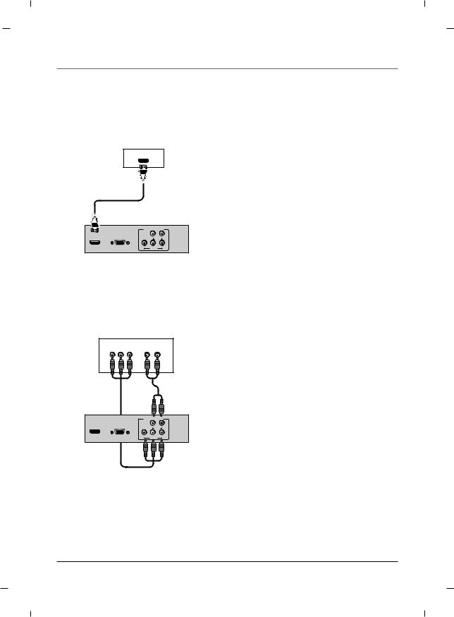
DVD Connection
A When connecting with a HDMI cable
DVD
HDMI-DVD OUTPUT
|
COMPONENT IN |
||
HDMI/DVI |
RGB IN |
|
|
IN |
(PC) |
L |
R |
|
|
AUDIO |
|
|
Y |
Pb |
Pr |
|
|
VIDEO |
|
Rear panel of the set
A When connecting with a Component cable
|
|
|
DVD |
Y |
Pb |
Pr |
(L) AUDIO (R) |
|
COMPONENT IN |
||
HDMI/DVI |
RGB IN |
|
|
IN |
(PC) |
L |
R |
|
|
AUDIO |
|
|
Y |
Pb |
Pr |
|
|
VIDEO |
|
Rear panel of the set
1.Connect the HDMI output of the DVD to the HDMI/DVI IN jack on the set.
2.Select HDMI input source using the INPUT button on the remote control.
3.Refer to the DVD player's manual for operating instructions.
1.Connect the video outputs (Y, PB, PR) of the DVD to the COMPONENT VIDEO(Y, Pb, Pr) jacks on the set.
2.Connect the audio outputs of the DVD to the
COMPONENT AUDIO L, R jacks on the set.
3.Turn on the DVD player, insert a DVD.
4.Select YPbPr source using the INPUT button on the remote control.
5.Refer to the DVD player's manual for operating instructions.
Chapter 1 |
25 |
Chapter 1: Connections and Setup
HDSTB Connection
-This TV can receive Digital Over-the-air/Cable signals without an external digital set-top box.
However, if you do receive Digital signals from a digital set-top box or other digital external device, refer to the figure as shown below.
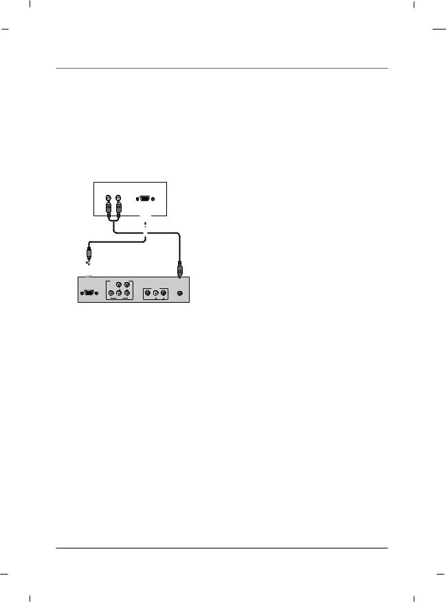
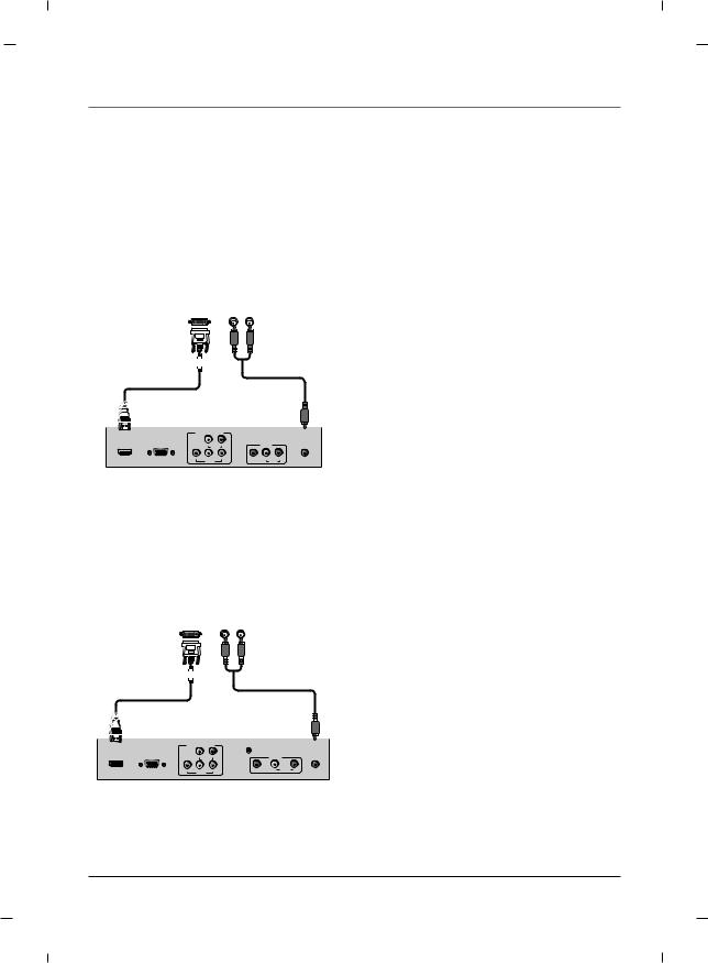
A When connecting with a D-Sub 15 pin cable - 26/32/42 inches
Digital Set-top Box
(R) AUDIO (L) |
RGB-DTV OUTPUT |
1.Connect the RGB output of the digital set-top box to the RGB IN (PC) jack on the set.
2.Connect the audio outputs of the set-top box to the AUDIO IN (RGB/DVI) jack on the set.
3. Turn on the digital set-top box.
4. Select VGA input source using the INPUT button on the remote control.
5. Refer to the digital set-top box manual for operating instructions.
COMPONENT IN |
|
|
|
||
RGB IN |
|
|
|
|
AUDIO IN |
(PC) |
L |
R |
|
AV1 |
(RGB/DVI) |
|
AUDIO |
|
|
|
|
Y |
Pb |
Pr |
VIDEO |
L |
R |
|
VIDEO |
|
|
|
AUDIO |
Rear panel of the set
A When connecting with a D-Sub 15 pin cable - 22 inch
Digital Set-top Box
(R) AUDIO (L) |
RGB-DTV OUTPUT |
1.Connect the RGB output of the digital set-top box to the RGB IN (PC) jack on the set.
2.Connect the audio outputs of the set-top box to the AUDIO IN (RGB/DVI) jack on the set.
3. Turn on the digital set-top box.
4. Select VGA input source using the INPUT button on the remote control.
5. Refer to the digital set-top box manual for operating instructions.
COMPONENT IN |
|
|
|
||
RGB IN |
|
|
SERVICE |
|
AUDIO IN |
|
|
|
|
||
(PC) |
L |
R |
|
AV1 |
(RGB/DVI) |
|
AUDIO |
|
|
|
|
Y |
Pb |
Pr |
VIDEO |
L AUDIO R |
|
|
VIDEO |
|
|
|
|
Rear panel of the set
26 |
Chapter 1 |
A When connecting with a HDMI to DVI cable - 26/32/42 inches
Digital Set-top Box
|
DVI-DTV OUTPUT |
(R) AUDIO (L) |
|
|
|
|
|||||||
|
|
|
|
|
|
|
|
|
|
|
|
|
|
|
|
|
|
|
|
|
|
|
|
|
|
|
|
|
|
|
|
|
|
|
|
|
|
|
|
|
|
|
|
|
|
|
|
|
|
|
|
|
|
|
|
|
|
|
|
|
|
|
|
|
|
|
|
|
|
|
|
|
|
|
|
|
|
|
|
|
|
|
|
|
|
|
|
|
|
|
|
|
|
|
|
|
|
|
|
|
|
|
|
|
|
|
|
|
|
|
|
|
|
|
|
|
|
|
|
|
|
|
|
|
|
|
|
|
|
|
|
|
|
|
|
|
|
|
|
|
|
|
|
|
|
|
|
|
|
|
|
|
|
|
|
|
|
|
|
|
|
|
|
|
|
|
|
|
|
|
|
|
|
|
|
|
|
|
|
|
|
|
|
|
|
|
|
|
|
|
|
|
|
|
|
|
COMPONENT IN |
|
|
|
||
HDMI/DVI |
RGB IN |
|
|
|
|
AUDIO IN |
IN |
(PC) |
L |
R |
|
AV1 |
(RGB/DVI) |
|
|
AUDIO |
|
|
|
|
|
Y |
Pb |
Pr |
VIDEO |
L |
R |
|
|
VIDEO |
|
|
|
AUDIO |
Rear panel of the set
1.Connect the DVI output of the digital set-top box to the HDMI/DVI IN jack on the set.
2.Connect the audio outputs of the set-top box to the AUDIO IN (RGB/DVI) jack on the set.
3.Turn on the digital set-top box.
4.Select HDMI input source using the INPUT button on the remote control.
5.Refer to the digital set-top box manual for operating instructions.
A When connecting with a HDMI to DVI cable - 22 inch
Digital Set-top Box
|
DVI-DTV OUTPUT |
(R) AUDIO (L) |
|
|
|
|
|||||||
|
|
|
|
|
|
|
|
|
|
|
|
|
|
|
|
|
|
|
|
|
|
|
|
|
|
|
|
|
|
|
|
|
|
|
|
|
|
|
|
|
|
|
|
|
|
|
|
|
|
|
|
|
|
|
|
|
|
|
|
|
|
|
|
|
|
|
|
|
|
|
|
|
|
|
|
|
|
|
|
|
|
|
|
|
|
|
|
|
|
|
|
|
|
|
|
|
|
|
|
|
|
|
|
|
|
|
|
|
|
|
|
|
|
|
|
|
|
|
|
|
|
|
|
|
|
|
|
|
|
|
|
|
|
|
|
|
|
|
|
|
|
|
|
|
|
|
|
|
|
|
|
|
|
|
|
|
|
|
|
|
|
|
|
|
|
|
|
|
|
|
|
|
|
|
|
|
|
|
|
|
|
|
|
|
|
|
|
|
|
|
|
|
|
|
|
COMPONENT IN
HDMI/DVI |
RGB IN |
|
|
SERVICE |
|
AUDIO IN |
IN |
(PC) |
L |
R |
|
AV1 |
(RGB/DVI) |
|
|
AUDIO |
|
|
|
|
|
Y |
Pb |
Pr |
VIDEO |
L AUDIO R |
|
|
|
VIDEO |
|
|
|
|
Rear panel of the set
1.Connect the DVI output of the digital set-top box to the HDMI/DVI IN jack on the set.
2.Connect the audio outputs of the set-top box to the AUDIO IN (RGB/DVI) jack on the set.
3.Turn on the digital set-top box.
4.Select HDMI input source using the INPUT button on the remote control.
5.Refer to the digital set-top box manual for operating instructions.
Chapter 1 |
27 |
Chapter 1: Connections and Setup
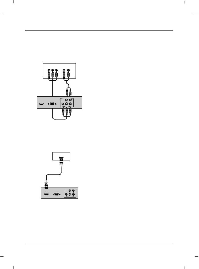
A When connecting with a Component cable
Digital Set-top Box
Y |
Pb |
Pr |
(L) AUDIO (R) |
|
COMPONENT IN |
||
HDMI/DVI |
RGB IN |
|
|
IN |
(PC) |
L |
R |
|
|
AUDIO |
|
|
Y |
Pb |
Pr |
|
|
VIDEO |
|
Rear panel of the set
1.Connect the video outputs (Y, PB, PR) of the digital set-top box to the COMPONENT VIDEO(Y, Pb, Pr) jacks on the set.
2.Connect the audio outputs of the digital set-top box to the COMPONENT AUDIO L, R jacks on the set.
3.Turn on the digital set-top box.
4.Select YPbPr source using the INPUT button on the remote control.
5.Refer to the digital set-top box manual for operating instructions.
A When connecting with a HDMI cable |
|
|
|||
|
|
|
|
1. |
Connect the HDMI output of the digital set-top |
|
Digital Set-top Box |
|
box to the HDMI/DVI IN jack on the set. |
||
|
HDMI-DTV OUTPUT |
|
|
2. |
Turn on the digital set-top box. |
|
|
|
|
||
|
|
|
|
3. |
Select HDMI input source using the INPUT button |
|
|
|
|
|
on the remote control. |
|
|
|
|
4. |
Refer to the digital set-top box manual for oper- |
|
|
|
|
|
ating instructions. |
|
COMPONENT IN |
|
|
||
HDMI/DVI |
RGB IN |
|
|
|
|
IN |
(PC) |
L |
R |
|
|
|
|
AUDIO |
|
|
|
|
Y |
Pb |
Pr |
|
|
|
|
VIDEO |
|
|
|
Rear panel of the set
28 |
Chapter 1 |
Chapter 1: Connections and Setup
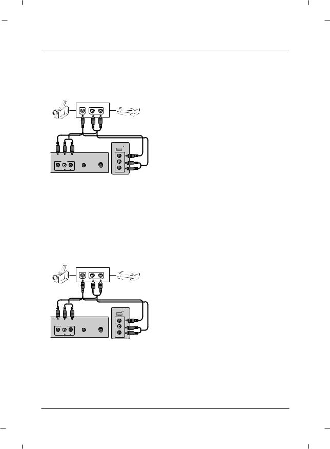
External A/V Source - 22/26 inches
Camcorder |
Video game set |
VIDEO |
L-AUDIO-R |
|
OUT |
|
|
|
|
USB IN |
|
|
|
AUDIO IN |
ANTENNA/ |
|
VIDEO |
|
AV1 |
|
L |
||
|
(RGB/DVI) |
CABLE IN |
AV2 |
- AUDIO - |
|
VIDEO |
L |
R |
|
||
|
|
AUDIO |
|
|
R |
Rear panel of the set |
Side panel of the set |
|
1.Connect the AUDIO/VIDEO jacks between TV and external equipment. Match the jack colors (Video = yellow, Audio Left = white, and Audio Right = red)
2.Select the AV1 or AV2 input source using the INPUT button on the remote control.
3.Operate the corresponding external equipment.
4.Refer to the external equipment manual for operating instructions.
External A/V Source - 32 inch
Camcorder |
Video game set |
VIDEO |
L-AUDIO-R |
|
OUT |
|
|
|
|
USB IN |
|
|
|
|
|
AV2 |
- R |
|
|
AUDIO IN |
ANTENNA/ |
AUDIO-L |
|
|
AV1 |
(RGB/DVI) |
CABLE IN |
|
|
VIDEO |
L |
AUDIO |
|
|
VIDEO |
R |
|
|
|
Rear panel of the set |
Side panel of the set |
|
1.Connect the AUDIO/VIDEO jacks between TV and external equipment. Match the jack colors (Video = yellow, Audio Left = white, and Audio Right = red)
2.Select the AV1 or AV2 input source using the INPUT button on the remote control.
3.Operate the corresponding external equipment.
4.Refer to the external equipment manual for operating instructions.
Chapter 1 |
29 |
 Loading...