


LDK 8000
Table of contents
 Loading...
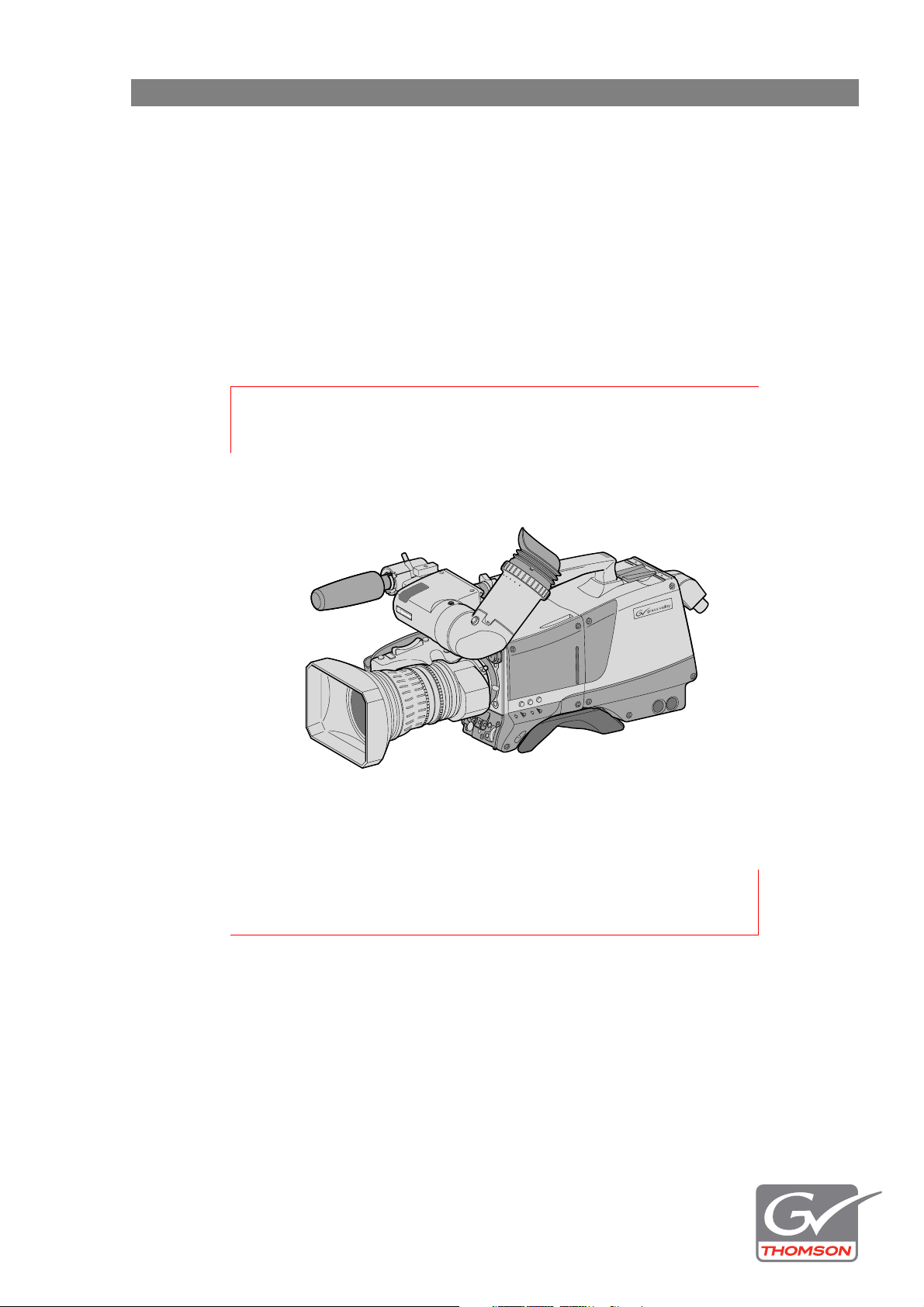
LDK 8000 HDTV camera system
User’s Guide
Standard version
WorldCam version
SportCam version
3922 496 30571 November 2007 v3.0

Declaration of Conformity
We, Grass Valley Nederland B.V., Kapittelweg 10, 4827 HG Breda, The
Netherlands, declare under our sole responsibility that this product is in
compliance with the following standards:
- EN60950 : Safety
- EN55103-1: EMC (Emission)
- EN55103-2: EMC (Immunity)
following the provisions of:
a. the Low Voltage directive 2006/95/EC
b. the EMC directive 2004/108/EC
FCC Class A Statement
This product generates, uses, and can radiate radio frequency energy and if not
installed and used in accordance with the instructions, may cause interference to
radio communications.
It has been tested and found to comply with the limits for a class A digital device
pursuant to part 15 of the FCC rules, which are designed to provide reasonable
protection against such interference when operated in a commercial environment.
Operation of this product in a residential area is likely to cause interference in
which case the user at his own expense will be required to take whatever
measures may be required to correct the interference.
Copyright
Copyright Grass Valley Nederland B.V. 2007. Copying of this document and giving it
to others, and the use or communication of the contents thereof, are forbidden
without express authority. Offenders are liable to the payment of damages. All
rights are reserved in the event of the grant of a patent or the registration of a
utility model or design. Liable to technical alterations in the course of further
development.
Trademarks
Grass Valley and Infinity are trademarks of Grass Valley, Inc. All other tradenames
referenced are service marks, trademarks, or registered trademarks of their
respective companies.
Website
Visit the Grass Valley public website to download the latest user’s guide updates
and additional information about your broadcast product:
www.thomsongrassvalley.com

LDK 8000 HDTV camera system User’s Guide (v3.0) 3
Table of contents
Chapter 1 – Introduction
1.1 Technology. . . . . . . . . . . . . . . . . . . . . . . . . . . . . . . . . . . . . . . . . . . . . . . . . . . . . . . . . .13
1.1.1 HD sensors . . . . . . . . . . . . . . . . . . . . . . . . . . . . . . . . . . . . . . . . . . . . . . . . . . . . 13
1.1.2 Digital processing . . . . . . . . . . . . . . . . . . . . . . . . . . . . . . . . . . . . . . . . . . . . . . . 13
1.1.3 Film-like characteristics . . . . . . . . . . . . . . . . . . . . . . . . . . . . . . . . . . . . . . . . . . . 14
1.1.4 Focus assist . . . . . . . . . . . . . . . . . . . . . . . . . . . . . . . . . . . . . . . . . . . . . . . . . . . .14
1.1.5 Standard version . . . . . . . . . . . . . . . . . . . . . . . . . . . . . . . . . . . . . . . . . . . . . . . .14
1.1.6 SportCam version . . . . . . . . . . . . . . . . . . . . . . . . . . . . . . . . . . . . . . . . . . . . . . . 14
1.1.7 WorldCam version . . . . . . . . . . . . . . . . . . . . . . . . . . . . . . . . . . . . . . . . . . . . . . .15
1.1.8 Advanced TriaxHD features . . . . . . . . . . . . . . . . . . . . . . . . . . . . . . . . . . . . . . . .15
1.1.9 SuperXPander . . . . . . . . . . . . . . . . . . . . . . . . . . . . . . . . . . . . . . . . . . . . . . . . . . 16
1.2 Features . . . . . . . . . . . . . . . . . . . . . . . . . . . . . . . . . . . . . . . . . . . . . . . . . . . . . . . . . . . .16
1.3 Accessories . . . . . . . . . . . . . . . . . . . . . . . . . . . . . . . . . . . . . . . . . . . . . . . . . . . . . . . . .18
Chapter 2 – Installation
2.1 Packing/unpacking. . . . . . . . . . . . . . . . . . . . . . . . . . . . . . . . . . . . . . . . . . . . . . . . . . . . 19
2.2 Transport case . . . . . . . . . . . . . . . . . . . . . . . . . . . . . . . . . . . . . . . . . . . . . . . . . . . . . . .20
2.3 Mounting a lens . . . . . . . . . . . . . . . . . . . . . . . . . . . . . . . . . . . . . . . . . . . . . . . . . . . . . .21
2.4 2-inch viewfinder . . . . . . . . . . . . . . . . . . . . . . . . . . . . . . . . . . . . . . . . . . . . . . . . . . . . . 22
2.4.1 Mounting viewfinder and microphone holder . . . . . . . . . . . . . . . . . . . . . . . . . . 22
2.4.2 Positioning the viewfinder . . . . . . . . . . . . . . . . . . . . . . . . . . . . . . . . . . . . . . . . . 23
2.5 Viewfinder accessories . . . . . . . . . . . . . . . . . . . . . . . . . . . . . . . . . . . . . . . . . . . . . . . . 24
2.5.1 Wide angle eyepiece . . . . . . . . . . . . . . . . . . . . . . . . . . . . . . . . . . . . . . . . . . . . . 24
2.5.2 Left eye adapter. . . . . . . . . . . . . . . . . . . . . . . . . . . . . . . . . . . . . . . . . . . . . . . . . 24
2.6 Mounting a microphone . . . . . . . . . . . . . . . . . . . . . . . . . . . . . . . . . . . . . . . . . . . . . . . 25
2.7 Tripod adapter plate . . . . . . . . . . . . . . . . . . . . . . . . . . . . . . . . . . . . . . . . . . . . . . . . . .26
2.8 Adjusting the shoulder pad. . . . . . . . . . . . . . . . . . . . . . . . . . . . . . . . . . . . . . . . . . . . . 27
2.9 Attaching an adapter . . . . . . . . . . . . . . . . . . . . . . . . . . . . . . . . . . . . . . . . . . . . . . . . . .28
Chapter 3 – Configurations
3.1 TriaxHD mode . . . . . . . . . . . . . . . . . . . . . . . . . . . . . . . . . . . . . . . . . . . . . . . . . . . . . . . 29
3.2 Multiple TriaxHD cameras with C2IP network. . . . . . . . . . . . . . . . . . . . . . . . . . . . . . 30
3.3 Camera with TriaxHD adapter and SuperXpander . . . . . . . . . . . . . . . . . . . . . . . . . .31
3.4 SportCam with high-speed Base Station. . . . . . . . . . . . . . . . . . . . . . . . . . . . . . . . . . 32
3.5 Local mode. . . . . . . . . . . . . . . . . . . . . . . . . . . . . . . . . . . . . . . . . . . . . . . . . . . . . . . . . .33
3.6 Triax cable lengths . . . . . . . . . . . . . . . . . . . . . . . . . . . . . . . . . . . . . . . . . . . . . . . . . . .34
Chapter 4 – Location of controls
4.1 Camera head controls and connectors . . . . . . . . . . . . . . . . . . . . . . . . . . . . . . . . . . . 35
4.2 TriaxHD adapter controls and connectors. . . . . . . . . . . . . . . . . . . . . . . . . . . . . . . . . 38
4.3 Viewfinder controls and indicators . . . . . . . . . . . . . . . . . . . . . . . . . . . . . . . . . . . . . .40

4 LDK 8000 HDTV camera system User’s Guide (v3.0)
Chapter 5 – Operating instructions
5.1 Using the camera. . . . . . . . . . . . . . . . . . . . . . . . . . . . . . . . . . . . . . . . . . . . . . . . . . . . .41
5.1.1 Switching on the power. . . . . . . . . . . . . . . . . . . . . . . . . . . . . . . . . . . . . . . . . . .41
5.1.2 Controlling the camera. . . . . . . . . . . . . . . . . . . . . . . . . . . . . . . . . . . . . . . . . . . .41
5.2 System Menu . . . . . . . . . . . . . . . . . . . . . . . . . . . . . . . . . . . . . . . . . . . . . . . . . . . . . . . .42
5.2.1 Entering the System menu . . . . . . . . . . . . . . . . . . . . . . . . . . . . . . . . . . . . . . . . 42
5.2.2 Finding your way . . . . . . . . . . . . . . . . . . . . . . . . . . . . . . . . . . . . . . . . . . . . . . . .43
5.2.3 Leaving the System Menu. . . . . . . . . . . . . . . . . . . . . . . . . . . . . . . . . . . . . . . . . 44
5.2.4 Making changes. . . . . . . . . . . . . . . . . . . . . . . . . . . . . . . . . . . . . . . . . . . . . . . . .44
5.2.5 Undoing changes . . . . . . . . . . . . . . . . . . . . . . . . . . . . . . . . . . . . . . . . . . . . . . . .44
5.3 Assigning functions to buttons. . . . . . . . . . . . . . . . . . . . . . . . . . . . . . . . . . . . . . . . . . 45
5.3.1 Side panel . . . . . . . . . . . . . . . . . . . . . . . . . . . . . . . . . . . . . . . . . . . . . . . . . . . . .45
5.3.2 Front. . . . . . . . . . . . . . . . . . . . . . . . . . . . . . . . . . . . . . . . . . . . . . . . . . . . . . . . . . 45
5.3.3 Lens . . . . . . . . . . . . . . . . . . . . . . . . . . . . . . . . . . . . . . . . . . . . . . . . . . . . . . . . . .45
5.4 Video acquisition modes. . . . . . . . . . . . . . . . . . . . . . . . . . . . . . . . . . . . . . . . . . . . . . .46
5.4.1 LDK 8000 Standard version . . . . . . . . . . . . . . . . . . . . . . . . . . . . . . . . . . . . . . . .46
5.4.2 LDK 8000 SportCam version . . . . . . . . . . . . . . . . . . . . . . . . . . . . . . . . . . . . . . . 46
5.4.3 LDK 8000 WorldCam version. . . . . . . . . . . . . . . . . . . . . . . . . . . . . . . . . . . . . . . 47
5.5 Viewfinder preferences . . . . . . . . . . . . . . . . . . . . . . . . . . . . . . . . . . . . . . . . . . . . . . . .48
5.5.1 Viewfinder picture quality . . . . . . . . . . . . . . . . . . . . . . . . . . . . . . . . . . . . . . . . .48
5.5.2 Video level indication . . . . . . . . . . . . . . . . . . . . . . . . . . . . . . . . . . . . . . . . . . . . .48
5.5.3 Tally indicators . . . . . . . . . . . . . . . . . . . . . . . . . . . . . . . . . . . . . . . . . . . . . . . . . .48
5.5.4 Viewfinder markers . . . . . . . . . . . . . . . . . . . . . . . . . . . . . . . . . . . . . . . . . . . . . .49
5.5.5 Focussing. . . . . . . . . . . . . . . . . . . . . . . . . . . . . . . . . . . . . . . . . . . . . . . . . . . . . .49
5.6 Lens preferences . . . . . . . . . . . . . . . . . . . . . . . . . . . . . . . . . . . . . . . . . . . . . . . . . . . . .50
5.6.1 Lens type . . . . . . . . . . . . . . . . . . . . . . . . . . . . . . . . . . . . . . . . . . . . . . . . . . . . . .50
5.6.2 Auto iris . . . . . . . . . . . . . . . . . . . . . . . . . . . . . . . . . . . . . . . . . . . . . . . . . . . . . . .50
5.6.3 Extended iris . . . . . . . . . . . . . . . . . . . . . . . . . . . . . . . . . . . . . . . . . . . . . . . . . . .50
5.6.4 Precision focus. . . . . . . . . . . . . . . . . . . . . . . . . . . . . . . . . . . . . . . . . . . . . . . . . .51
5.6.5 Lens indicators in the viewfinder . . . . . . . . . . . . . . . . . . . . . . . . . . . . . . . . . . . . 51
5.7 Video preferences . . . . . . . . . . . . . . . . . . . . . . . . . . . . . . . . . . . . . . . . . . . . . . . . . . . . 52
5.7.1 Standard settings . . . . . . . . . . . . . . . . . . . . . . . . . . . . . . . . . . . . . . . . . . . . . . . . 52
5.7.2 Test signal . . . . . . . . . . . . . . . . . . . . . . . . . . . . . . . . . . . . . . . . . . . . . . . . . . . . .53
5.7.3 Gain selection . . . . . . . . . . . . . . . . . . . . . . . . . . . . . . . . . . . . . . . . . . . . . . . . . .53
5.7.4 Optical filter selection . . . . . . . . . . . . . . . . . . . . . . . . . . . . . . . . . . . . . . . . . . . .54
5.7.5 Colour temperature selection . . . . . . . . . . . . . . . . . . . . . . . . . . . . . . . . . . . . . .55
5.7.6 Exposure time . . . . . . . . . . . . . . . . . . . . . . . . . . . . . . . . . . . . . . . . . . . . . . . . . .58
5.7.7 Shooting screens . . . . . . . . . . . . . . . . . . . . . . . . . . . . . . . . . . . . . . . . . . . . . . . .59
5.7.8 Reverse scan . . . . . . . . . . . . . . . . . . . . . . . . . . . . . . . . . . . . . . . . . . . . . . . . . . .60
5.7.9 Black stretch . . . . . . . . . . . . . . . . . . . . . . . . . . . . . . . . . . . . . . . . . . . . . . . . . . .60
5.7.10 Auto skin detail . . . . . . . . . . . . . . . . . . . . . . . . . . . . . . . . . . . . . . . . . . . . . . . . .60
5.8 Controls on the TriaxHD adapter . . . . . . . . . . . . . . . . . . . . . . . . . . . . . . . . . . . . . . . .61
5.8.1 Powering the camera. . . . . . . . . . . . . . . . . . . . . . . . . . . . . . . . . . . . . . . . . . . . .61
5.8.2 Selecting monitoring signals . . . . . . . . . . . . . . . . . . . . . . . . . . . . . . . . . . . . . . . 62
5.8.3 Using audio . . . . . . . . . . . . . . . . . . . . . . . . . . . . . . . . . . . . . . . . . . . . . . . . . . . .63
5.8.4 Intercom. . . . . . . . . . . . . . . . . . . . . . . . . . . . . . . . . . . . . . . . . . . . . . . . . . . . . . . 65
5.8.5 Communication . . . . . . . . . . . . . . . . . . . . . . . . . . . . . . . . . . . . . . . . . . . . . . . . .66
5.9 Managing files . . . . . . . . . . . . . . . . . . . . . . . . . . . . . . . . . . . . . . . . . . . . . . . . . . . . . . .67
5.9.1 Scene files . . . . . . . . . . . . . . . . . . . . . . . . . . . . . . . . . . . . . . . . . . . . . . . . . . . . .67
5.9.2 Operator files . . . . . . . . . . . . . . . . . . . . . . . . . . . . . . . . . . . . . . . . . . . . . . . . . . .67
5.9.3 Standard files . . . . . . . . . . . . . . . . . . . . . . . . . . . . . . . . . . . . . . . . . . . . . . . . . . .67
5.9.4 Customer standard files. . . . . . . . . . . . . . . . . . . . . . . . . . . . . . . . . . . . . . . . . . .68

LDK 8000 HDTV camera system User’s Guide (v3.0) 5
5.10 User levels . . . . . . . . . . . . . . . . . . . . . . . . . . . . . . . . . . . . . . . . . . . . . . . . . . . . . . . . . . 68
5.10.1 Selecting the user level . . . . . . . . . . . . . . . . . . . . . . . . . . . . . . . . . . . . . . . . . . .68
5.11 Access and Security . . . . . . . . . . . . . . . . . . . . . . . . . . . . . . . . . . . . . . . . . . . . . . . . . .69
5.11.1 Camera cards. . . . . . . . . . . . . . . . . . . . . . . . . . . . . . . . . . . . . . . . . . . . . . . . . . . 69
5.11.2 Access control . . . . . . . . . . . . . . . . . . . . . . . . . . . . . . . . . . . . . . . . . . . . . . . . . . 70
5.11.3 Camera card slot . . . . . . . . . . . . . . . . . . . . . . . . . . . . . . . . . . . . . . . . . . . . . . . . 70
Chapter 6 – Menu structure and contents
6.1 Menu structure. . . . . . . . . . . . . . . . . . . . . . . . . . . . . . . . . . . . . . . . . . . . . . . . . . . . . . . 71
6.1.1 Top menu structure . . . . . . . . . . . . . . . . . . . . . . . . . . . . . . . . . . . . . . . . . . . . . . 71
6.1.2 VF menu structure . . . . . . . . . . . . . . . . . . . . . . . . . . . . . . . . . . . . . . . . . . . . . . . 72
6.1.3 Lens menu structure . . . . . . . . . . . . . . . . . . . . . . . . . . . . . . . . . . . . . . . . . . . . .73
6.1.4 Video menu structure . . . . . . . . . . . . . . . . . . . . . . . . . . . . . . . . . . . . . . . . . . . . 74
6.1.5 Install menu structure (Triax version). . . . . . . . . . . . . . . . . . . . . . . . . . . . . . . . . 75
6.1.6 File menu structure . . . . . . . . . . . . . . . . . . . . . . . . . . . . . . . . . . . . . . . . . . . . . . 76
6.1.7 Security menu structure . . . . . . . . . . . . . . . . . . . . . . . . . . . . . . . . . . . . . . . . . . 77
6.1.8 Diagnostics menu structure. . . . . . . . . . . . . . . . . . . . . . . . . . . . . . . . . . . . . . . . 77
6.1.9 Service menu structure . . . . . . . . . . . . . . . . . . . . . . . . . . . . . . . . . . . . . . . . . . . 77
6.2 Menu contents . . . . . . . . . . . . . . . . . . . . . . . . . . . . . . . . . . . . . . . . . . . . . . . . . . . . . . . 78
6.2.1 VF menu . . . . . . . . . . . . . . . . . . . . . . . . . . . . . . . . . . . . . . . . . . . . . . . . . . . . . .78
6.2.2 Lens menu. . . . . . . . . . . . . . . . . . . . . . . . . . . . . . . . . . . . . . . . . . . . . . . . . . . . . 80
6.2.3 Video menu . . . . . . . . . . . . . . . . . . . . . . . . . . . . . . . . . . . . . . . . . . . . . . . . . . . . 81
6.2.4 Install menu . . . . . . . . . . . . . . . . . . . . . . . . . . . . . . . . . . . . . . . . . . . . . . . . . . . . 85
6.2.5 Files menu . . . . . . . . . . . . . . . . . . . . . . . . . . . . . . . . . . . . . . . . . . . . . . . . . . . . . 89
6.2.6 Security menu . . . . . . . . . . . . . . . . . . . . . . . . . . . . . . . . . . . . . . . . . . . . . . . . . . 90
6.2.7 Diagnostics menu . . . . . . . . . . . . . . . . . . . . . . . . . . . . . . . . . . . . . . . . . . . . . . .91
6.2.8 Service menu. . . . . . . . . . . . . . . . . . . . . . . . . . . . . . . . . . . . . . . . . . . . . . . . . . . 93
Chapter 7 – Connectors
7.1 Camera connectors . . . . . . . . . . . . . . . . . . . . . . . . . . . . . . . . . . . . . . . . . . . . . . . . . . . 95
7.1.1 Viewfinder connector. . . . . . . . . . . . . . . . . . . . . . . . . . . . . . . . . . . . . . . . . . . . . 96
7.1.2 VF/Mon connector . . . . . . . . . . . . . . . . . . . . . . . . . . . . . . . . . . . . . . . . . . . . . . . 96
7.1.3 Lens connector . . . . . . . . . . . . . . . . . . . . . . . . . . . . . . . . . . . . . . . . . . . . . . . . . 97
7.1.4 Audio microphone connector. . . . . . . . . . . . . . . . . . . . . . . . . . . . . . . . . . . . . . . 97
7.1.5 RS232 serial connector . . . . . . . . . . . . . . . . . . . . . . . . . . . . . . . . . . . . . . . . . . . 97
7.2 Connectors on the TriaxHD adapter. . . . . . . . . . . . . . . . . . . . . . . . . . . . . . . . . . . . . . 98
7.2.1 Triax connector . . . . . . . . . . . . . . . . . . . . . . . . . . . . . . . . . . . . . . . . . . . . . . . . . 99
7.2.2 Viewfinder / External video output connector . . . . . . . . . . . . . . . . . . . . . . . . . . 99
7.2.3 HD - SDI (B) connector . . . . . . . . . . . . . . . . . . . . . . . . . . . . . . . . . . . . . . . . . . . 99
7.2.4 HD - SDI (A) connector . . . . . . . . . . . . . . . . . . . . . . . . . . . . . . . . . . . . . . . . . . . 99
7.2.5 Audio microphone 1 connector . . . . . . . . . . . . . . . . . . . . . . . . . . . . . . . . . . . . 100
7.2.6 Audio microphone 2 connector . . . . . . . . . . . . . . . . . . . . . . . . . . . . . . . . . . . . 100
7.2.7 Intercom headset connector . . . . . . . . . . . . . . . . . . . . . . . . . . . . . . . . . . . . . . 100
7.2.8 DC power input socket . . . . . . . . . . . . . . . . . . . . . . . . . . . . . . . . . . . . . . . . . .101
7.2.9 DC power and tally output socket . . . . . . . . . . . . . . . . . . . . . . . . . . . . . . . . . . 101
7.2.10 Script light power supply socket . . . . . . . . . . . . . . . . . . . . . . . . . . . . . . . . . . . 101
7.2.11 Teleprompter output / Reference input connector . . . . . . . . . . . . . . . . . . . . . 102
7.2.12 Tracker communications connector. . . . . . . . . . . . . . . . . . . . . . . . . . . . . . . . . 102
7.2.13 Auxiliary connector . . . . . . . . . . . . . . . . . . . . . . . . . . . . . . . . . . . . . . . . . . . . .103
Chapter 8 – Specifications
8.1 Specifications for LDK 8000 . . . . . . . . . . . . . . . . . . . . . . . . . . . . . . . . . . . . . . . . . . .105

6 LDK 8000 HDTV camera system User’s Guide (v3.0)
8.2 Specifications for LDK 5860 TriaxHD adapter . . . . . . . . . . . . . . . . . . . . . . . . . . . . .106
8.2.1 Dimensions . . . . . . . . . . . . . . . . . . . . . . . . . . . . . . . . . . . . . . . . . . . . . . . . . . . 107

LDK 8000 HDTV camera system User’s Guide (v3.0) 7
End-of-life product recycling
Grass Valley’s innovation and excellence in product design also extends to the programs we’ve
established to manage the recycling of our products. Grass Valley has developed a
comprehensive end-of-life product take back program for recycle or disposal of end-of-life
products. Our program meets the requirements of the European Union’s WEEE Directive and
in the United States from the Environmental Protection Agency, individual state or local
agencies.
Grass Valley’s end-of-life product take back program assures proper disposal by use of Best
Available Technology. This program accepts any Grass Valley branded equipment. Upon
request, a Certificate of Recycling or a Certificate of Destruction, depending on the ultimate
disposition of the product, can be sent to the requester.
Grass Valley will be responsible for all costs associated with recycling and disposal, including
freight, however you are responsible for the removal of the equipment from your facility and
packing the equipment ready for pickup.
For further information on the Grass Valley product take back system please contact Grass
Valley at + 800 80 80 20 20 or +33 1 48 25 20 20 from most other countries. In the US and
Canada please call 800-547-8949 or 530-478-4148. Ask to be connected to the EH&S
Department. In addition, information concerning the program can be found at:
www.thomsongrassvalley.com/environment

8 LDK 8000 HDTV camera system User’s Guide (v3.0)
Important information
Read these instructions carefully and retain them for future reference.
During installation and operation of this equipment, local building safety and fire protection
standards must be observed.
Before connecting the equipment to the power supply of the installation, verify the proper
functioning of the protective earth lead.
Whenever it is likely that safe operation is impaired, the apparatus must be made inoperative
and secured against any unintended operation. The appropriate servicing authority must then
be informed. For example, safety is likely to be impaired if the apparatus fails to perform the
intended function or shows visible damage.
Any changes or modifications not expressly approved in this manual could void your authority
to operate this equipment.
Cautions and Warnings
Read and comply with the warning and caution notices that appear in the manual.
• Warnings indicate danger that requires correct procedures or practices to prevent death or
injury to personnel.
• Cautions indicate procedures or practices that should be followed to prevent damage or
destruction to equipment or property.

LDK 8000 HDTV camera system User’s Guide (v3.0) 9
Warnings
To prevent fire or shock hazard, do not expose the unit to rain or moisture. If the unit is in a wet
or damp environment, a rain cover must be used to protect it for personal safety reasons
(EN60065). The rain cover supplied with the unit protects it according to safety specification
EN60529 up to level IPX2 (spraying water).
To avoid electrical shock, do not remove covers or panels. Refer servicing to qualified
personnel only.
In case of an emergency ensure that the power is disconnected.
Use only fuses of the type and rating specified.
Connect the product only to a power source with the specified voltage rating.
The Base Station must always be connected to protective earth. Do not interrupt the
protection conductor inside or outside the unit. Do not disconnect the protective earth
terminal. Intentional interruption is prohibited and is likely to make the unit dangerous.
To prevent risk of overheating, ventilate the units correctly.
For safety reasons the Base Station must be mounted in a 19-inch rack which has safety covers
according to IEC65. When two Base Stations are mounted above each other, the minimum
distance between them must be 50mm or the rack must be force-air cooled.

10 LDK 8000 HDTV camera system User’s Guide (v3.0)
Triax cable systems
Only connect a Triax cable from the same LDK camera family to the unit.
Do not allow system earth currents to exceed 1.5A in the outer shield of the Triax cable or 0.2A
in other cable shields.
To avoid excessive earth currents in a Triax system, galvanically separate the power earth
connection of equipment connected to the camera from the camera earth.
It is strictly prohibited to short circuit the inner and outer shields of a Triax cable used to
connect a camera to a base station.
Galvanic separation
Because of the nature of Triax systems, with long distances between camera and Base
Station, the risk of earth currents flowing is greater. These earth currents can result in damage
to the equipment.
For example, a monitor connected directly to the CVBS output of the camera is powered
locally. The earthing point of the monitor’s power supply can be at a different potential with
respect to the earthing point of the Base Station. If the power earth of the monitor is also the
video earth, then this earth potential is transferred to the camera via the shield of the BNC
connector. The difference in earth potential between the camera and the Base Station results
in an earth current in the Triax system.
To prevent earth currents from flowing in the Triax system, we recommend galvanic separation
of earthed equipment connected to the camera. This separation can be achieved by using an
isolation transformer between the local power outlet and the equipment connected to the
camera. Alternatively, use equipment that has a double insulation and therefore does not
require an earth connection.

LDK 8000 HDTV camera system User’s Guide (v3.0) 11
Base Station earthing
The rear of the unit has two separate screw terminals for protective earth (PE) and video
earth (VE). These are normally connected by a metal strap.
The protective earth terminal is internally connected to the protective earth conductor of the
power cable. In normal circumstances the connection between the protective earth and the
video earth should not be broken. If required, the central earth connection wire of the studio
can be connected to terminal PE in accordance with VDE regulation 0800/part2.
Only if the studio (or OB van) is equipped with separate protective and video earth systems
may the metal strap be removed. Under these circumstances the video earth terminal must be
connected to the central functional earth potential (video earth) of the studio. This earth
potential should have functional protective and noiseless earth (FPE) qualities as stated in the
VDE regulation 0800/part2. A low impedance interconnection of both earth conductors must
be provided at the central studio earthing point.
Metal strap
VE
PE

12 LDK 8000 HDTV camera system User’s Guide (v3.0)
Precautions
To ensure continual high performance from the camera take the following precautions into
consideration:
• Avoid very damp places. If the environment is wet or damp a rain cover must be used to
protect the unit.
• Do not subject the unit to severe shocks or vibration.
• Do not expose the camera to extremes of temperature.
• Do not leave the unit in direct sunlight or close to heating appliances for extended periods.
• Do not allow sunlight to shine into the viewfinder.
• Do not allow LASER beams to shine into the lens as this could damage the CCD sensors.
• Avoid extreme highlights as these can cause various kinds of optical reflections.
• Be careful when connecting and disconnecting triax cables.
– Do not mix triax units from different types of camera systems (HD with SD, RGB triax
with digital triax).
– Make connections swiftly and firmly to avoid false error messages.
Mains lead wiring for UK users
The wires in the mains lead are coloured in accordance with the following code:
GREEN and YELLOW- EARTH
BLUE- NEUTRAL
BROWN- LIVE
As the colours of the wires in the mains lead of this apparatus may not correspond with the
coloured markings identifying the terminals in your plug proceed as follows:
• The wire coloured GREEN AND YELLOW must be connected to the terminal on the plug
marked with the letter E or by the safety earth symbol
or coloured GREEN or GREEN
AND YELLOW.
• The wire coloured BROWN must be connected to the terminal marked with the letter L or
coloured RED.
• The wire coloured BLUE must be connected to the terminal marked with the letter N or
coloured BLACK.
Ensure that your equipment is connected correctly - if you are in any doubt consult a qualified
electrician.

LDK 8000 HDTV camera system User’s Guide (v3.0) 13
Chapter 1 - Introduction
Chapter 1
Introduction
1.1 Technology
The LDK 8000 is a high definition multi-standard, multi-format digital camera head using
three 2/3-inch HD-DPM
+
™ sensors. The camera head can be combined with the TriaxHD
adapter for a flexible camera that is equally at home in the studio or out on location.
The SportCam version can capture true progressive HD images, natively, in multiple formats
and frame rates. It supports 2x high-speed acquisition at either 100
Hz or 119.88 Hz.
1.1. 1 HD sensors
The camera head uses HD-DPM
+
™ CCD sensors which offer superior performance and
ultimate flexibility. Native wide screen pictures in the high-definition formats 1080i, 1080p
(WorldCam) and 720p are produced at the touch of a button. This unique native multi-format
capability is realized with innovative 9.2 million pixel 2/3" CCD sensors. These allow vertically
grouping of different numbers of pixels on the sensors themselves. There is no need for HDTV
format conversion during digital signal processing which would lead to quality degradation.
These sensors have a high dynamic range and high linear sensitivity across all camera lens
apertures. They are based on Frame Transfer technology, which ensures that there is neither
lag nor smear.
1.1. 2 Digital processing
The advanced digital processing of the camera is based on 14-bit A/D converters and more
than 22-bit internal processing. All major camera functions are processed in the digital
domain, including knee, gamma, detail, matrix and colour correction.
The intelligent continuous automatics facility provides automatic control of black levels and
black shading. Each sensor provides black reference signals that are used to monitor
temperature changes. This means that continuous automatic correction is applied without
operator intervention.
The digital detail processing uses full amplitude video RGB signals via an extended dynamic
range detail circuit. Colorimetry is selected by means of a variable 6-point digital matrix or via
preset matrices. Digital gamma circuits provide a wide range of standardised gamma curves
and enable soft contrast in black scenes to be enhanced, together with hard contrast and
saturated colour in bright scenes. The matrix and gamma sequence is software programmable
for precise colour matching.

14 LDK 8000 HDTV camera system User’s Guide (v3.0)
Chapter 1 - Introduction
1.1. 3 Film-like characteristics
The pivoting knee circuit adapts both the knee point and the compression ratio according to
the highlight content of the picture to emulate the softly limiting S-shaped transfer
characteristics of film. Digital True Colour Knee circuitry maintains the correct hue for
compressed highlights, reproducing colours faithfully, even overexposed skin tones.
Digital contrast circuitry provides a black stretch function for more detail in black areas and a
black press function for improving the contrast impression by simulating the S-curve of film.
1.1. 4 Focus assist
With HDTV, focusing is even more critical than before. The LDK 8000 has special patented
focusing aids. A unique viewfinder zoom function enlarges the viewfinder image instantly
with a simple press-button action, thus providing improved means for focusing. A patented
crawler circuitry adds motion in the viewfinder to objects in sharp focus.
1.1. 5 Standard version
The Standard version supports 1080i/720p HD formats in 50, and 59.94 Hz, and
simultaneously provides high-quality SDTV outputs in either 50 Hz or 59.94 Hz.
The following acquisition formats are available for the Standard version:
– 1080i at 59.94 Hz
– 1080i at 50 Hz
– 720p at 59.94 Hz
– 720p at 50Hz
1.1. 6 SportCam version
The SportCam version provides, in addition to the Standard version formats, high-speed
acquisition formats that are output as a two-phase signal from the high-speed base station.
The following acquisition formats are available for the SportCam version:
– 1080i at 59.94 Hz
– 1080i at 119.88 Hz
– 1080i at 50 Hz
– 1080i at 100 Hz
– 720p at 59.94 Hz
– 720p at 119.88 Hz
– 720p at 59.94 Hz
– 720p at 100Hz

LDK 8000 HDTV camera system User’s Guide (v3.0) 15
Chapter 1 - Introduction
1.1. 7 WorldCam version
The WorldCam version provides, in addition to the Standard version formats, digital
cinematography formats in 1080p and 720p, which give an impression of motion comparable
to film cameras running at identical speeds.
The WorldCam also provides convenient built-in frame-rate conversions for easy connection
to existing HD peripherals, offering possibilities for cost-effective monitoring and recording
combined with the motion portrayal of film cameras. The 1080p format at 23.98 Hz, for
example, can be converted using 3:2 pull-down to 1080i at 59.94 Hz right inside the camera.
The following acquisition formats are available for the WorldCam version:
– 1080i at 59.94 Hz
– 1080i at 50 Hz
– 1080p at 23.98 Hz
– 1080p at 24 Hz
– 1080p at 25 Hz
– 1080p at 29.97 Hz
– 720p at 59.94 Hz
– 720p at 50 Hz
– 720p at 23.98 Hz
– 720p at 25 Hz
– 720p at 29.97 Hz
1.1. 8 Advanced TriaxHD features
TriaxHD, which is a further development of the Emmy Award winning triax transmission
system, makes the camera compatible with industry standard triax cables. This allows the
reuse of existing, reliable and valuable cable inventories.
TriaxHD allows video transmission and remote control of cameras up to a distance of 1,200 m
(4,000 ft.) and beyond, using industry standard 14 mm triax cables. It is based on 30MHz full-
bandwidth 4:2:2 transmission (Y/Cr/Cb components).
The double side band modulation technique used in combination with Y/Cr/Cb transmission
ensures linearity, resolution and an optimal signal-to-noise ratio over the maximum cable
length. Bandwidth efficient channel combining and equalization techniques minimize cross-
talk and interference. Teleprompter and viewfinder signals maintain high performance with
relatively long cable lengths.
The communication facilities provide for two-wire or four-wire high quality intercom signals.
Full camera control is provided via a C2IP Ethernet-based control network.
The TriaxHD adapter is equipped with a rotary triax connector which provides freedom of
movement during portable use of the camera and protects the connector from being
damaged in near-floor conditions.

16 LDK 8000 HDTV camera system User’s Guide (v3.0)
Chapter 1 - Introduction
TriaxHD Base Station
The TriaxHD Base Station, as well as providing high definition outputs, optionally offers
simultaneous high-end SDTV outputs. This facilitates a gradual and managed transition from
SDTV to HDTV.
TriaxHD high-speed Base Station
The SportCam when used together with TriaxHD high-speed Base Station provides a digital
dual-phase high-speed output. This 2x SDI connection can be supplied to an external disk
recorder to obtain exceptional slow motion playback performance.
1.1. 9 SuperXPander
The optional avaiable SuperXpander together with the 7-inch HD high resolution viewfinder
turns the portable Triax camera into a full-featured studio camera for studio and EFP
situations.
1.2 Features
• Ultimate flexibility with HD-DPM+ ™ CCD sensors, offering native switchability between
the interlaced 1080i and true progressive 1080p high definition digital cinematography
formats.
• The CCDs have 9.2 million pixels, with 1920 (H) x 4320 (V) effective picture elements.
• Frame Transfer technology ensures no smear.
• 14-bit A-to-D and more than 22-bit digital processing with unique software programmable
video path.
• Superior all digital highlight handling with a wide dynamic range.
• Unique circuitry for pivoting knee and True Colour Knee.
• Variable gain control and variable colour temperature.
• Wide range of presets and variable 6-point digital matrix assure accurate colour matching.
• Fluorescent light matrix.
• Digital gamma with unique standard preset values and highest accuracy.
• Digital detail with an extensive range of parameters.
• Advanced detail correction includes two automatic skin settings.
• Intelligent Continuous Automatics black levels, black shading and video levels - no set-up
time required.
• Digital contrast with standard black stretch and black press.
• International standard 2/3-inch lens interface.
• Optical servo-controlled four-position neutral density filter wheel.
• Optical servo-controlled effect filter wheel with soft focus, four-point star and six-point star
filters.

LDK 8000 HDTV camera system User’s Guide (v3.0) 17
Chapter 1 - Introduction
• Electronic colour filter can be used for creating a special look (warm/cold) of a scene, or
for a smooth colour temperature control around the white balance setting.
• Smart card for personal settings and security.
• Owner card for setting user levels, and for copying and storing control settings.
• Protected, easy-to-operate controls and switches with read-out of all settings.
• Viewfinder status read-out of primary camera functions.
• Clean scan feature allows capture of computer and other monitor pictures.

18 LDK 8000 HDTV camera system User’s Guide (v3.0)
Chapter 1 - Introduction
1.3 Accessories
Xpander LDK 4489
SuperXpander LDK 4488
7” viewfinder support LDK 6517
HD/HS Triax Repeater LDK 4800
2” viewfinder HDTV LDK 5302/60
5” viewfinder HDTV LDK 5305/01
7” viewfinder HDTV LDK 4021
Wide Angle adapter for 2” viewfinder LDK 5390/00
Left eye adapter for 2” viewfinder LDK 5390/10
Sunhood for 5” viewfinder LDK 6992/02
Raincover for camera with 5” viewfinder LDK 5021/05
Tripod plate LDK 5031/10
Headset dynamic XLR-5 double muff LDK 8111/37
Headset dynamic XLR-5 single muff LDK 8111/51
Scriptboard with light LDK 6985/21
Transport/flightcase LDK 5020/00
Carrying bag LDK 5020/01
AC power supply 100 W LDK 5901/00

LDK 8000 HDTV camera system User’s Guide (v3.0) 19
Chapter 2 - Installation
Chapter 2
Installation
2.1 Packing/unpacking
Inspect the shipping container for evidence of damage immediately after receipt. If the
shipping container or cushioning material is damaged, it should be kept until the contents of
the shipment have been checked for completeness and the units have been checked
mechanically and electrically.
The shipping container should be placed upright and opened from the top. Remove the
cushioning material and lift out the contents. The contents of the shipment should be checked
against the packing list. If the contents are incomplete, if there is mechanical damage or
defect, or if the units do not perform correctly when unpacked, notify your Grass Valley
Nederland B.V. sales or service centre within eight days. If the shipping container shows signs
of damage or stress, notify the carrier as well.
If a unit is being returned to Grass Valley Nederland B.V. for servicing, try to use the containers
and materials of the original packaging. Attach a tag indicating the type of service required,
return address, model number, full serial number and the return number which will be supplied
by your Grass Valley Nederland B.V. service centre.
If the original packing can no longer be used, the following general instructions should be used
for repacking with commercially available materials:
1. Wrap unit in heavy paper or plastic.
2. Use strong shipping container.
3. Use a layer of shock-absorbing material around all sides of the unit to provide firm
cushioning and prevent movement inside container.
4. Seal shipping container securely.
5. Mark shipping container FRAGILE to ensure careful handling.
20 LDK 8000 HDTV camera system User’s Guide (v3.0)
Chapter 2 - Installation
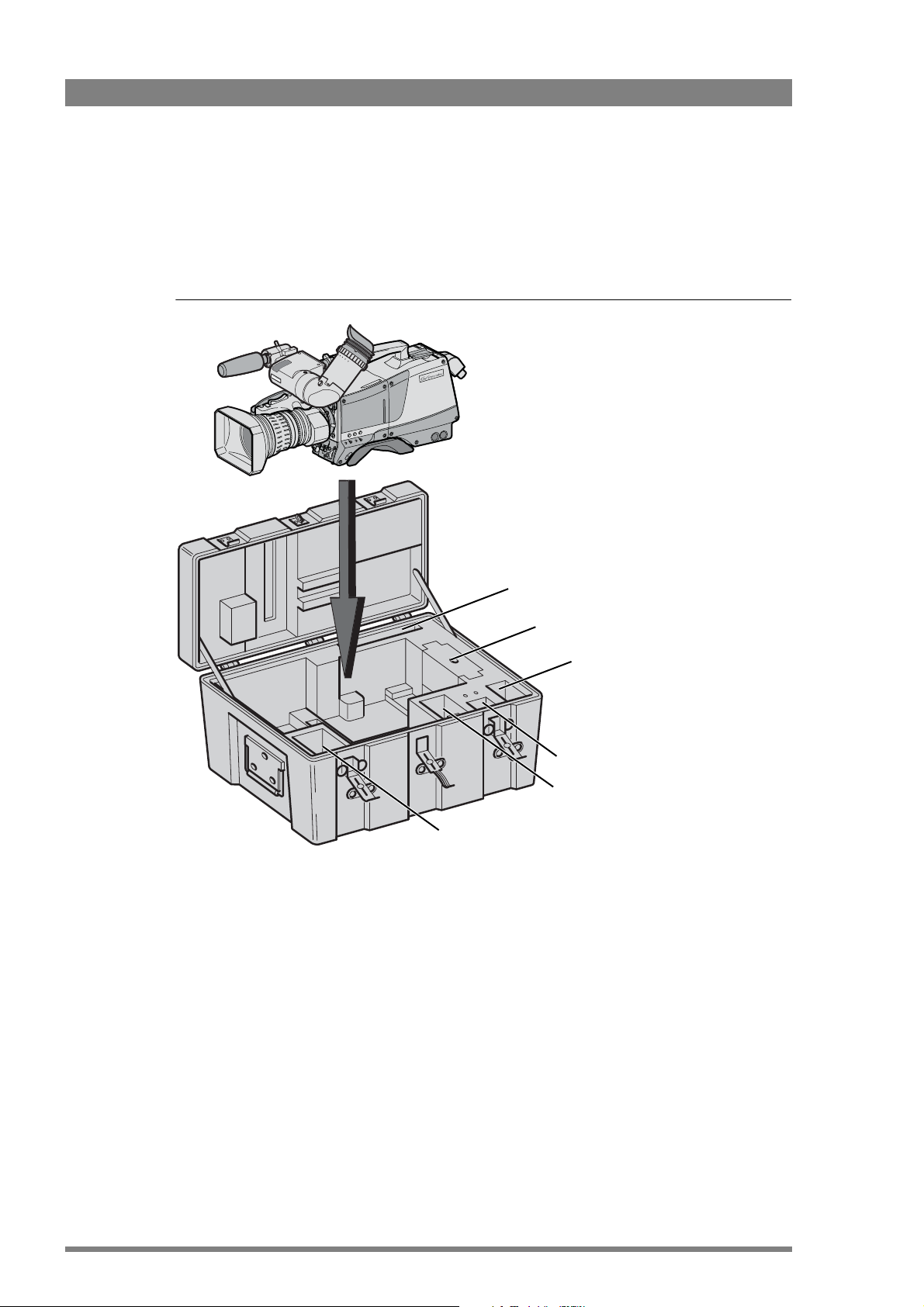
2.2 Transport case
It is important to protect your camera against damage when transporting it. To do this, a
transport case (LDK 5020/00) is optionally available for the camera, lens, viewfinder and some
accessories.
Figure 2-1. Transport case
The camera is packed in the transport case as shown in the figure above. This ensures that the
camera is not damaged during transport. Turn the 2-inch viewfinder downwards so that it does
not protrude above the top of the camera. Several foam packing inserts are provided to enable
different configurations of the camera to be packed securely. These inserts are used to support
the rear of the camera. Make sure you use the correct foam insert for your particular
configuration.
documentation
packing inserts
top light
tripod plate
power supply
additional
supplies

LDK 8000 HDTV camera system User’s Guide (v3.0) 21
Chapter 2 - Installation
2.3 Mounting a lens
To attach a lens to the camera head proceed as follows:
1. Ensure that the lens locking ring (1) is in the unlocked position - turned counterclockwise.
2. Remove the dust protection cap (2).
3. Slot the lens into the lens mount (3).
4. Turn the lens locking ring (1) clockwise to lock the lens in place.
5. Connect the lens cable to the lens connector (4) at the right side of the camera.
6. Place the lens cable into the bottom clip at the front of the camera and clip (5) located at
the side.
Figure 2-2. Lens mounting
Caution
Do not attach a lens weighing more than 5 kg to the camera without a support.
When a new lens is fitted to the camera it may be necessary to carry out some adjustments to
optimize its use, for example, back focus or shading. For more information about these
adjustments refer to the lens manufacturer’s documentation.
☞
Note
Always mount the dust protection cap when the lens is not connected to the camera.
4
5
3
2
1
22 LDK 8000 HDTV camera system User’s Guide (v3.0)
Chapter 2 - Installation
2.4 2-inch viewfinder
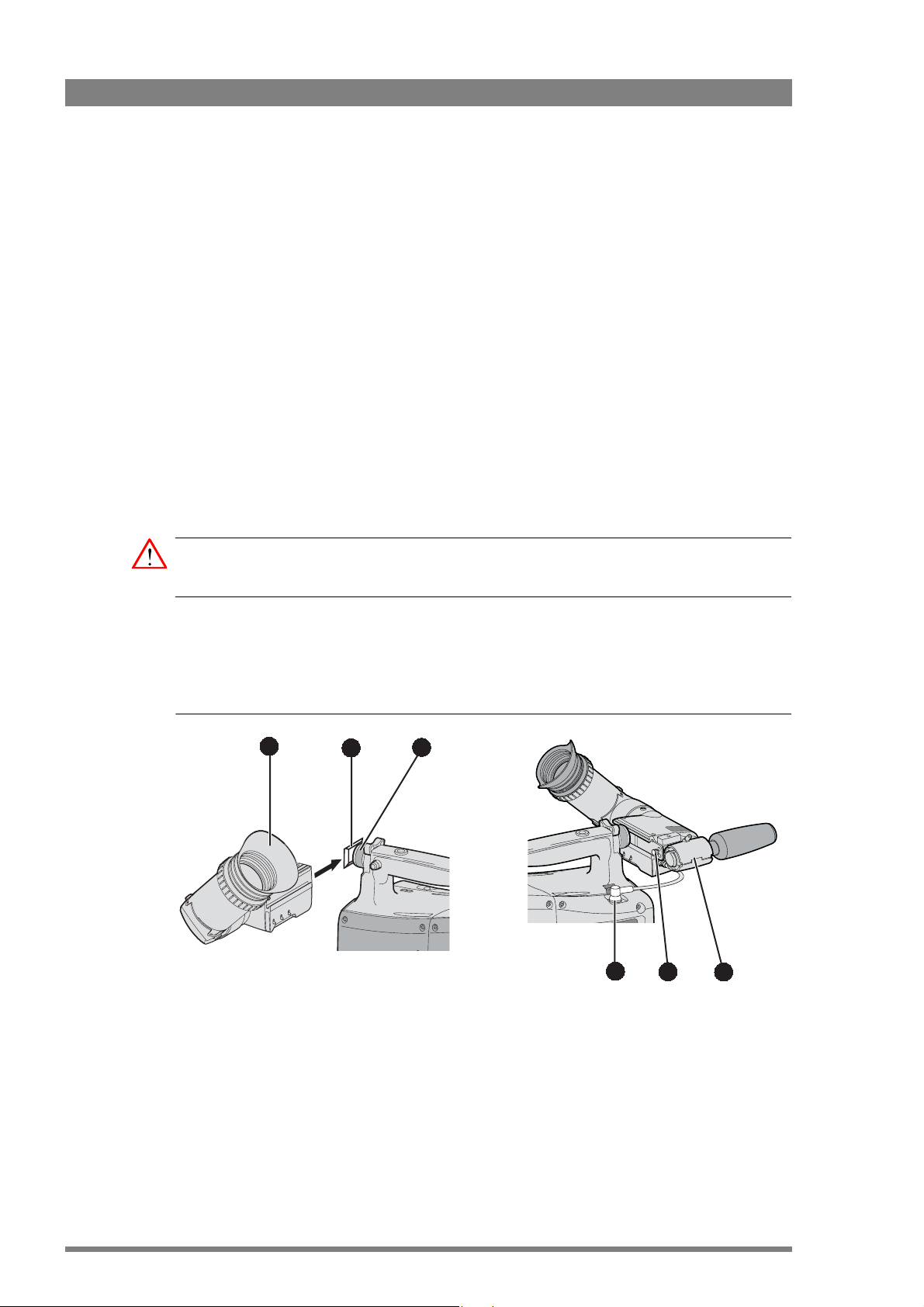
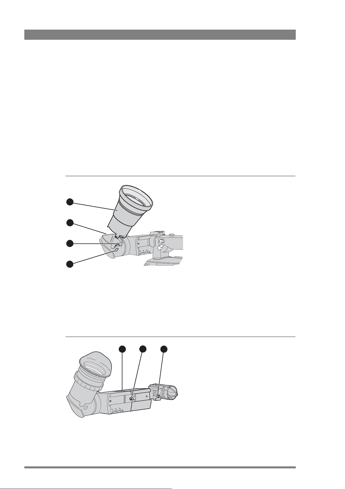
2.4.1 Mounting viewfinder and microphone holder
To mount the viewfinder LDK 5302/60 proceed as follows:
1. Loosen locking ring (1) of viewfinder support bracket (2) at the front of the camera handle.
(As seen from the rear of the camera, turning the locking ring counterclockwise moves it
towards the handle.)
2. Slide the viewfinder onto the viewfinder support bracket.
3. Tighten the locking ring (1) by turning it clockwise (as seen from rear) so that the
viewfinder is mounted securely to the support.
4. Connect the viewfinder cable to the viewfinder connector socket (6) at the top right of the
camera.
5. Slide the microphone holder (4) onto the viewfinder and secure with the knurled screw
(5).
Caution
Always fit the microphone holder as it functions as a safety stop for the viewfinder.
6. To improve the comfort of the skin contact when using the viewfinder, fit the eye piece
cover (3) to the rubber eyepiece. Spare eye piece covers (ordering number
3922
405 00461) are available at your Grass Valley representative.
Figure 2-3. Viewfinder mounting
3
2
1
5
6
4
LDK 8000 HDTV camera system User’s Guide (v3.0) 23
Chapter 2 - Installation
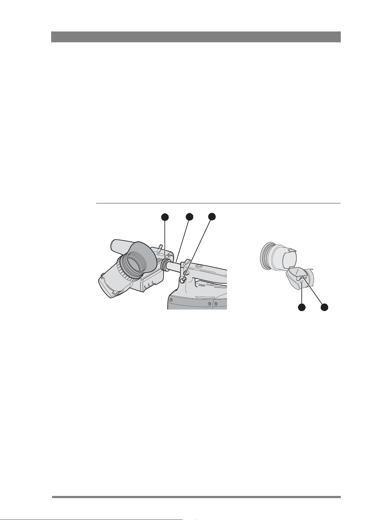
2.4.2 Positioning the viewfinder
The horizontal position of the viewfinder can be adjusted as follows to suit your requirements:
1. Loosen the locking ring (1). (As seen from the rear of the camera, turning the locking ring
counterclockwise moves it towards the handle.)
2. Slide the viewfinder horizontally along the rail to the desired position.
3. Tighten the locking ring (1) by turning clockwise.
The dioptre hood and eyepiece of the viewfinder can be rotated vertically.
The viewfinder can be positioned backwards and forwards along the camera axis. Loosen the
support bracket round bar retaining lever (2) and slide the round bar (3) forwards or backwards.
When the desired position is reached tighten the support bracket round bar retaining lever (2)
again.
To use the viewfinder at a distance press the button (4) below or above the eyepiece tube and
swing it free of the associated clip (5). The display can now be seen from further away.
Figure 2-4. Viewfinder positioning
5
4
2
1
3
24 LDK 8000 HDTV camera system User’s Guide (v3.0)
Chapter 2 - Installation
2.5 Viewfinder accessories
2.5.1 Wide angle eyepiece
If you regularly use the viewfinder at a distance, for example, when you use the camera in the
hand-held position, it is recommended that you fit the optionally available wide angle eyepiece
(LDK 5390/00). To fit the wide angle eyepiece proceed as follows:
1. Hold the eyepiece (1) securely.
2. Press the button (2) below the eyepiece tube and swing it free of the button clip (3).
3. Press the button (4) above the eyepiece tube and remove the eyepiece.
4. Fit the wide angle eyepiece (1) to the two clips (3) ensuring that they both click into place.
Figure 2-5. Viewfinder wide angle eyepiece
2.5.2 Left eye adapter
A left eye adapter is optionally available (LDK 5390/10) to allow the viewfinder to be used with
the left eye. Before mounting the viewfinder onto the camera, attach the left eye adapter (1) to
the viewfinder and secure it using the screw (2). Do not forget to mount the microphone
support bracket (3) at the end of the left eye adapter.
Figure 2-6. Viewfinder left eye adapter
4
2
1
3
2
1
3
LDK 8000 HDTV camera system User’s Guide (v3.0) 25
Chapter 2 - Installation
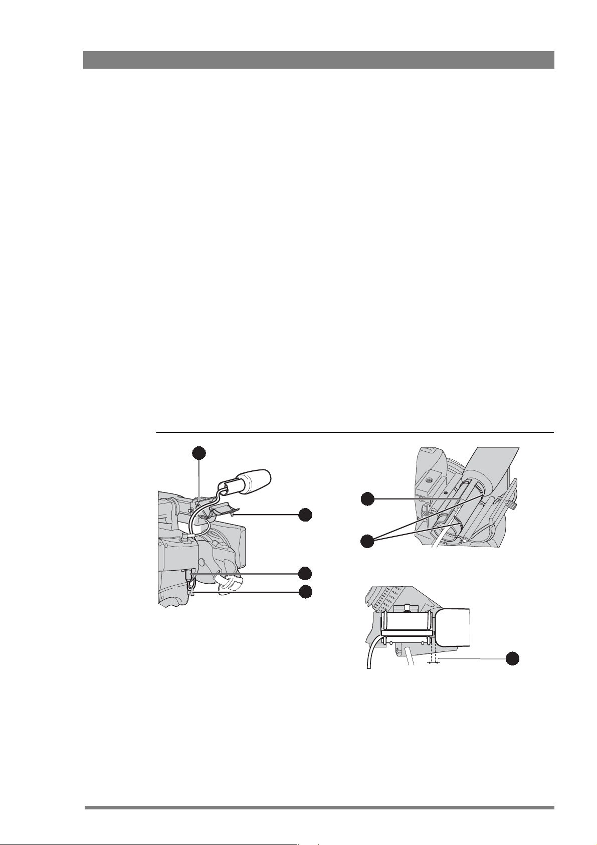
2.6 Mounting a microphone
To attach the optional microphone (AJ-MC700) to the camera proceed as follows:
1. Open the microphone holder by unscrewing the knurled screw (2) of the microphone
support bracket (1) on the viewfinder and open.
2. Slide the microphone into the split tube until the microphone shoulder reaches the mark
(5) in the tube.
3. Place the tube with the microphone into the holder with the split facing upwards. Mount
the microphone as straight as possible.
4. Ensure that the rubber supports at the back and front of the holder fit into the rims (6)
around the tube.
5. Close the holder and tighten the knurled screw at the top. Don’t allow the wind hood to
touch the holder (7) as this reduces the damping effect.
6. Connect the microphone cable to the MIC audio connector (3) on the right side of the
camera. To avoid mechanical pick-up, do not let the microphone cable touch the holder.
7. Place the microphone cable into the top clip at the front of the camera and into clip (4) at
the side of the camera. (Pull and twist clip to open it.)
Other microphones with a diameter of 21mm can also be used, however, ensure that the
sensitivity of the input that match that type of microphone are correctly selected in the camera
INSTALL menu. When a longer microphone is used, it is not necessary to place it in the split
tube. Phantom power is always present on the front microphone socket.
Figure 2-7. Microphone mounting
2
4
1
3
5
7
6

26 LDK 8000 HDTV camera system User’s Guide (v3.0)
Chapter 2 - Installation
2.7 Tripod adapter plate
To mount the camera on a tripod, the tripod plate LDK 5031/10 must first be attached to the
tripod. Follow the tripod manufacturer’s instructions to mount the wedge plate supplied with
the tripod and the tripod adapter plate firmly onto the tripod. Attach the camera to the tripod
adapter plate as follows:
1. Slide the camera horizontally along the tripod adapter plate from back to front ensuring
that the front of the camera engages the V-slot (1) at the front of the tripod adapter plate,
and that the slot on the bottom of the camera engages the stud (2) at the rear of the tripod
adapter plate.
2. Firmly push the camera forward until it clicks into place.
3. When the camera is mounted firmly, the locking lever (5) swings around fully to the rear of
the plate. If the lever does not travel the full distance, you should manually lock it into
place.
Caution
Failure to attach the camera to the tripod adapter plate in the correct manner could result in an
unsecured camera. Ensure that the rear stud (2) is engaged and that the camera clicks into
place.
Figure 2-8. Tripod adapter plate
Remove the camera from the tripod as follows:
1. Open the locking lever (5) to free the rear stud (2).
2. Press and hold the red locking lever (3) against the release handle (4).
3. Ensure that you have a firm hold of the camera.
4. Pull the release handle (4) forward.
5. Move the camera backwards and up.
4
1
3
2
5
LDK 8000 HDTV camera system User’s Guide (v3.0) 27
Chapter 2 - Installation
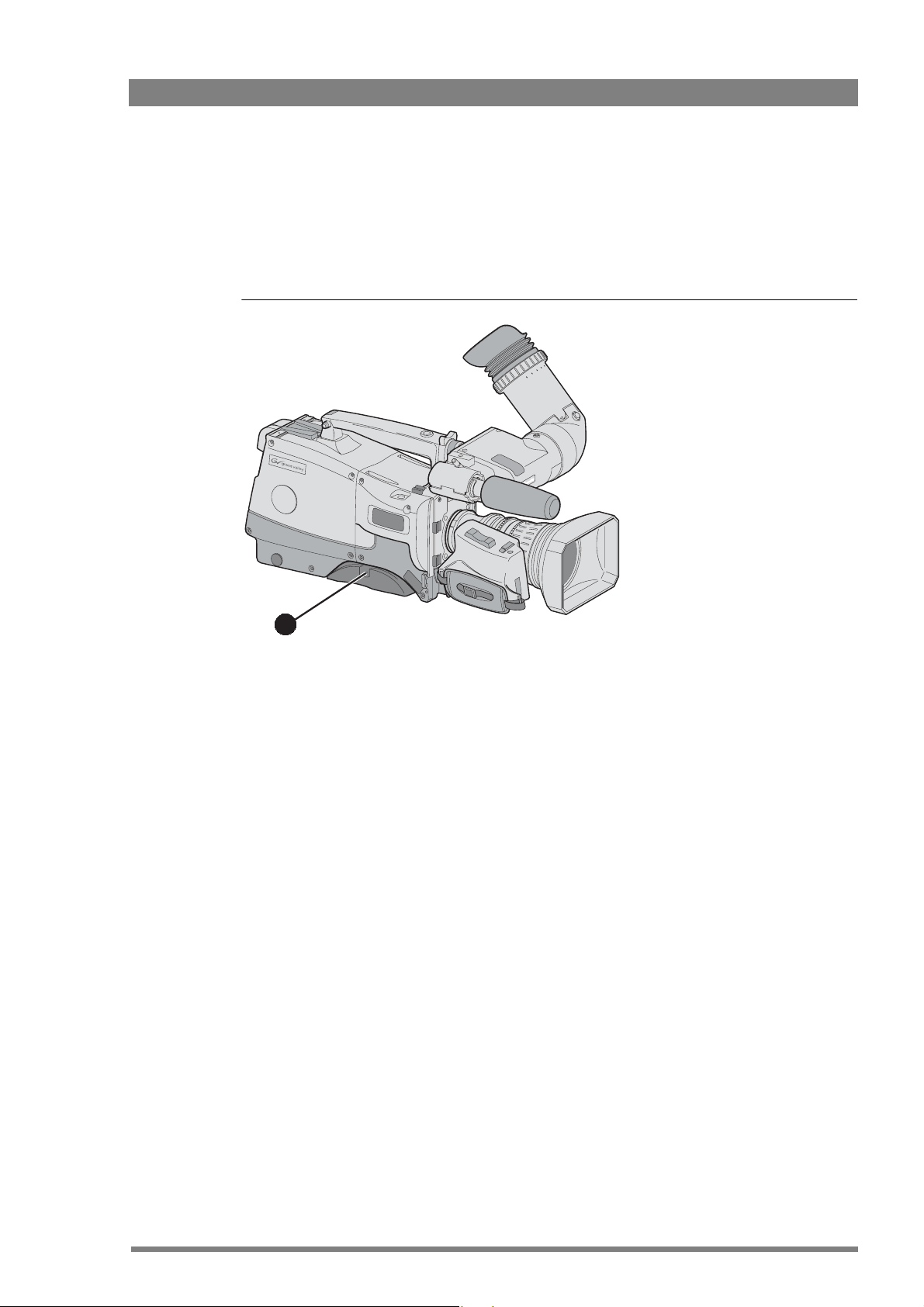
2.8 Adjusting the shoulder pad
To change the position the shoulder pad press and hold lever (1). The shoulder pad can now be
moved backwards and forwards along the axis of the camera. Adjust the shoulder pad when all
units have been mounted to get the best balanced shoulder position.
Figure 2-9. Shoulder pad
1

28 LDK 8000 HDTV camera system User’s Guide (v3.0)
Chapter 2 - Installation
2.9 Attaching an adapter
The camera head is a multi-role camera head that can be used with various adapters.
Caution
Be extremely careful with the connectors between the camera head and the adapter. Do not
allow the guide pins to damage the pins of the connector. Follow these steps in the order
given. Tightening or loosening the screws in the wrong order could result in mechanical
damage to the camera.
To attach an adapter to the camera proceed as follow:
1. Fit the guide pin at the top rear of the camera head and the guide pins on either side of
the camera connector into the corresponding slots (1 and 2) of the adapter.
2. First, tighten the two horizontal screws (3) on the top of camera.
3. Next, tighten the two horizontal screws (4) at the front of the camera.
4. Lastly, tighten the vertical screw (5) in the handle of the camera.
To detach an adapter from the camera head follow the steps for attaching it in the reverse
order.
Figure 2-10. Attaching an adapter
5 1
4
3
2

LDK 8000 HDTV camera system User’s Guide (v3.0) 29
Chapter 3 - Configurations
Chapter 3
Configurations
3.1 TriaxHD mode
A camera head with the LDK 5860 TriaxHD adapter is connected to a TriaxHD Base Station
using a Triax cable. The maximum length of cable that can be used without significant
degradation of the video signal is 1,200 m (4,000 ft.) for a 14 mm Triax cable.
The power supply is applied to the Base Station and via the Triax cable to the camera. An
OCP 400 operational control panel can be connected directly to the Base Station using a cross-
over Ethernet cable.
Figure 3-1. Camera in TriaxHD mode
Camera Base Station
Camera head + Triax adapter
Base Station
OCP 400
Cross over Ethernet cable
Teleprompter
Tracker
headphone
Audio
out
Video
out
Power
in
TP
in
External
video in
Camera
operator
headphone

30 LDK 8000 HDTV camera system User’s Guide (v3.0)
Chapter 3 - Configurations
3.2 Multiple TriaxHD cameras with C2IP network
The Base Stations are each connected to a network hub or router via an Ethernet cable
(straight through, not cross-over). The OCP 400 operational control panels and, if required the
MCP 400 Master Control Panel, are also connected to the Ethernet network via a hub or
router.
Figure 3-2. Multiple HD cameras with C2IP network control
Camera Base Station
Camera Base Station
Camera head
Triax adapter
Base Station
Triax cable
Ethernet cable
Hub or switch
Ethernet cable
OCP 400
MCP 400
OCP 400 OCP 400
Loading...