


WHP150 MANUAL(1J1500 ) 6/10/99 11:28 AM Page 1
|
|
|
Radio Frequency |
|
|
W i r e l e s s |
|
900 |
|
|
|
|
|
|
|
||
|
|
|
|
|
|
H e a d p h o n e s |
|
M H z |
|
|
|
w i t h 9 0 0 M H z T r a n s m i t t e r |
|
|
|
|
|
|
|
|
|
|
|
T
r
its ansm
S
te
r
e
o
Si g n
a l
F r e e d o m F r o m W i r e s |
|
|
UP TO |
|
|
listen anywhere in your home |
|
125F E E T |
|
|
|
E |
|
|
|
|
|
v |
|
|
|
|
m |
n |
|
|
|
|
|
e |
O |
|
|
|
o |
|
|
|
r |
||
|
|
ut |
u |
H |
|
|
|
|
side Yo |
|
|
e
WHP150 MANUAL(1J1500 ) 6/10/99 11:28 AM Page 2
INTRODUCTION
The 900 MHz stereo wireless headphone system uses latest wireless technology that enables you to enjoy music and TV sound anywhere inside or outside your home. You can simply connect the system to any sound source such as CD, TV, VCR, Hi-Fi and radio. It is also perfect for usage in class rooms, hospitals, meetings, churches, as a hearing aid, and for the purpose of language translation.
FEATURES
•900 MHz Radio Frequency (RF) technology
•RF technology lets you roam freely throughout your home
•Operating distance up to 125 ft.
•No line-of-sight limitations
•Built-in charger in the transmitter
•Virtually interference free stereo quality
•Automatic Level Control and auto ON/OFF control.
2
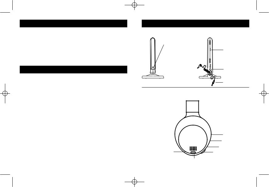
SYSTEM COMPONENTS
RADIO TRANSMITTER
Auto Power |
|
|
ON/Signal |
Frequency |
|
Strength |
Adjustment |
|
Indicator (Green) |
|
|
Charge Indicator |
Charge Output |
|
(Red) |
||
Plug (connects |
||
|
||
|
to headphones |
|
|
for charging) |
|
|
Audio Cord |
HEADPHONE RECEIVER
|
Power Indicator |
|
On/Off Switch |
|
Charge Input |
Stereo Indicator |
Volume Control |
|
|
|
Tune |
3

WHP150 MANUAL(1J1500 ) 6/10/99 11:28 AM Page 4
INSTALLATION OF TRANSMITTER
1)Connect the supplied AC power adapter to an electrical wall outlet.
2)Plug the AC power Adapter into the DC jack located on the rear of the transmitter.
Charge |
AC/DC |
Green |
Adapter |
||
Output |
|
LED |
Jack |
Audio |
|
|
|
|
|
Cord |
|
3)Locate the audio cord connected at the back of the transmitter. The 3.5 mm plug provided can be used to connect the transmitter to the headphone jack of any audio source.
If your equipment has a 1/4” size jack, use the adapter plug included with the headphone.
For connection to RCA type phono jacks located on the back of a TV, VCR or A/V receiver, use the “Y” adapter that is included. Just insert the mini plug on the audio cord into the jack on the adapter to convert the connector for this application. Then insert the red and white RCA plug ends into the equipment jacks marked “Audio Out” to make the audio source connection (see diagram).
4
AUDIO
INPUT
Audio |
|
LEFT |
|
RIGHT |
|
Cord |
1/4" adapter |
“Y” adapter |
|
INSTALLATION OF BATTERIES
1)Open the battery compartment cover on the right side of the headphone.
2)Insert two AA size Ni-Cd rechargeable batteries with the correct polarity.
3)Replace the cover and you are ready to charge the batteries.
Battery
Door
5
 Loading...