


INSTALLATION MANUAL MANUEL D’INSTALLATION
NAVIGATION AV SYSTEM
SISTEMA DE NAVEGACIÓN AV
NAVIGATIONS-/AV-SYSTEM
SYSTEME DE NAVIGATION AV
SISTEMA DI NAVIGAZIONE AV
AV NAVIGATIESYSTEEM
AVIC-F9210BT AVIC-F9220BT
Some wiring and installation are described in the separate installation manual.
En el manual de instalación independiente se describe parte del proceso de cableado e instalación.
Gewisse Verkabelungsund Installationsarbeiten sind in der separaten Einbauanleitung beschrieben.
Certains câblages et procédés d’installation sont décrits dans le manuel d’installation séparé.
Alcuni dati di cablaggio e installazione sono descritti nel Manuale d’installazione separato.
Sommige bedradingsen installatie-informatie staat in de afzonderlijke installatiehandleiding.
Nederlands Italiano Français Deutsch Español English


 Contents
 IMPORTANT INFORMATION
ABOUT YOUR NEW NAVIGATION SYSTEM AND THIS MANUAL 3
 IMPORTANT SAFEGUARDS
PLEASE READ ALL OF THESE INSTRUCTIONS REGARDING YOUR NAVIGATION SYSTEM AND RETAIN THEM
FOR FUTURE REFERENCE |
4 |
|
||
Connecting the system |
|
|
||
Precautions before connecting the |
|
|||
system 5 |
|
|
|
|
Before installing this product |
5 |
|
||
To prevent damage |
6 |
|
|
|
– |
Notice for the blue/white lead |
6 |
||
– |
Notice for the violet/white lead |
6 |
||
Parts supplied 7 |
|
|
|
|
– |
AVIC-F9210BT |
7 |
|
|
– |
AVIC-F9220BT |
7 |
|
|
Connecting the system 8
When connecting to separately sold power amp 10
When connecting a rear view camera 12 When connecting the external video
component 13 |
|
|
– |
Using “AV1 Input” (AV1) |
13 |
– |
Using “AV2 Input” (AV2) |
14 |
When connecting the rear display 14
– When using a rear display connected to
rear video output |
14 |
|
|
Installation |
|
|
|
Precautions before installation |
15 |
||
To guard against electromagnetic |
|||
interference |
15 |
|
|
Before installing |
15 |
|
|
Installing the navigation system |
16 |
||
– Installation notes |
16 |
|
|
Concealing the metal brackets |
17 |
||
Installing the GPS aerial |
18 |
|
– |
Installation notes |
18 |
– |
Parts supplied 18 |
|
–When installing the aerial inside the vehicle (on the dashboard or rear shelf) 19
Installing the microphone 20
– |
Parts supplied 20 |
– |
Mounting on the sun visor 20 |
– |
Installation on the steering column 21 |
– |
Adjusting the microphone angle 21 |
 2
2 Engb
Engb

 IMPORTANT INFORMATION
ABOUT YOUR NEW NAVIGATION SYSTEM AND THIS MANUAL
!The navigation features of this product (and rear view camera option if purchased) are intended solely to aid you in the operation of your vehicle. It is not a substitute for your attentiveness, judgement and care when driving.
!Never use this navigation system to route to hospitals, police stations, or similar facilities in an emergency. Please call the appropriate emergency number.
!Do not operate this navigation system (or the rear view camera option if purchased) if doing so will divert your attention in any way from the safe operation of your vehicle. Always observe safe driving rules and follow all existing traffic regulations. If you experience difficulty in operating the system or reading the display, park your vehicle in a safe location and apply the handbrake before making the necessary adjustments.
!This manual explains how to install this navigation system in your vehicle. However, some wiring and installation are described in the separate installation manual. Operation of this navigation system is explained in a separate manual.
!Do not install this product where it may (i) obstruct the driver’s vision, (ii) impair the performance of any of the vehicle’s operating systems of safety features, including airbags, hazard lamp buttons or (iii) impair the driver’s ability to safely operate the vehicle. In some cases, it may not be possible to install this product because of the vehi-
cle type or the shape of the vehicle interior.
Section
01
English
Engb  3
3

Section
02  IMPORTANT SAFEGUARDS
 WARNING
Pioneer does not recommend that you install your navigation system yourself. We recommend that only authorised Pioneer service personnel, who have special training and experience in mobile electronics, set up and install this product. NEVER SERVICE THIS PRODUCT YOURSELF. Installing or servicing this product and its connecting cables may expose you to the risk of electric shock or other hazards, and can cause damage to the navigation system that is not covered by warranty.
siderably more severe if your seat belt is not properly fastened.
7Certain country and government laws may prohibit or restrict the placement and use of this system in your vehicle. Please comply with all applicable laws and regulations re-
garding the use, installation and operation of your navigation system.
PLEASE READ ALL OF THESE INSTRUCTIONS REGARDING YOUR NAVIGATION SYSTEM AND RETAIN THEM FOR FUTURE REFERENCE
1Read this manual fully and carefully before installing your navigation system.
2Keep this manual handy for future reference.
3Pay close attention to all warnings in this manual and follow the instructions carefully.
4This navigation system may in certain circumstances display erroneous information regarding the position of your vehicle, the distance of objects shown on the screen, and compass directions. In addition, the system has certain limitations, including the inability to identify one-way streets, temporary traffic restrictions and potentially unsafe driving areas. Please exercise your own judgement in the light of actual driving conditions.
5As with any accessory in your vehicle’s interior, the navigation system should not divert your attention from the safe operation of your vehicle. If you experience difficulty in operating the system or reading the display, please make adjustments while safely parked.
6Please remember to wear your seat belt at all times while operating your vehicle. If you are ever in an accident, your injuries can be con-
 4
4 Engb
Engb
 Connecting the system
Precautions before |
Before installing this product |
connecting the system |
! Use this unit with a 12-volt battery and ne- |
CAUTION |
gative earthing only. Failure to do so may |
result in a fire or malfunction. |
|
! If you decide to perform the installation |
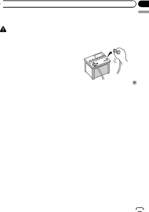
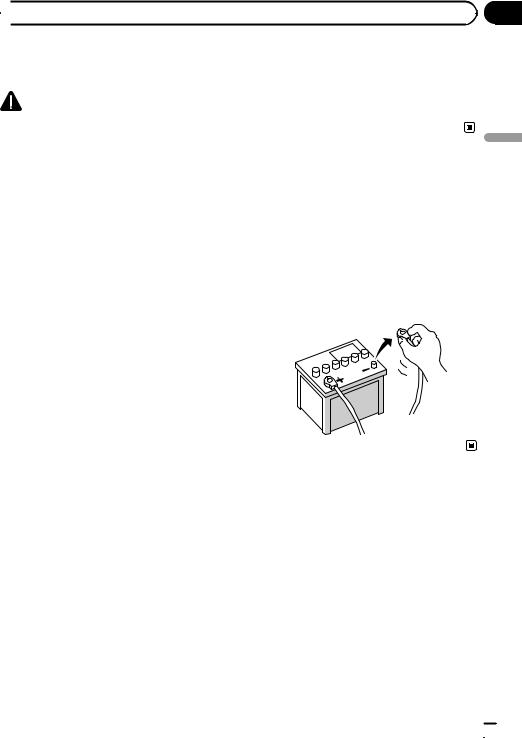
! To avoid shorts in the electrical system, be |
yourself, and have special training and ex- |
sure to disconnect the (–) battery cable be- |
perience in the mobile electronics instal- |
fore beginning installation. |
lations, please carefully follow all of the |
|
steps in the installation manual. |
|
! Secure all wiring with cable clamps or |
|
electrical tape. Do not allow any bare wir- |
|
ing to remain exposed. |
|
!It is extremely dangerous to allow the cables to become wound around the steer-
ing column or gearstick. Be sure to install this product, its cables, and wiring away in such a way that they will not obstruct or hinder driving.
!Make sure that the cables and wires are routed and secured so they will not interfere with or become caught in any of the vehicle’s moving parts, especially the steering wheel, gearstick, handbrake, sliding seat tracks, doors, or any of the vehicle’s controls.
!Do not route wires where they will be exposed to high temperatures. If the insulation heats up, wires may become damaged, resulting in a short circuit or malfunction and permanent damage to the product.
!Do not cut the GPS aerial cable to shorten it or use an extension to make it longer. Altering the aerial cable could result in a short circuit or malfunction.
!Do not shorten any leads. If you do, the protection circuit (fuse holder, fuse resistor or filter, etc.) may fail to work properly.
!Never feed power to other electronic products by cutting the insulation of the power supply lead of the navigation system and tapping into the lead. The current
capacity of the lead will be exceeded, causing overheating.
Section
03
English
Engb  5
5
Section
03  Connecting the system
To prevent damage
 WARNING
!Use speakers over 50 W (output value) and between 4 W to 8 W (impedance value). Do not use 1 W to 3 W speakers for this
unit.
!When replacing the fuse, be sure to only use a fuse of the rating prescribed on this product.
!When disconnecting a connector, pull the connector itself. Do not pull the lead, as you may pull it out of the connector.
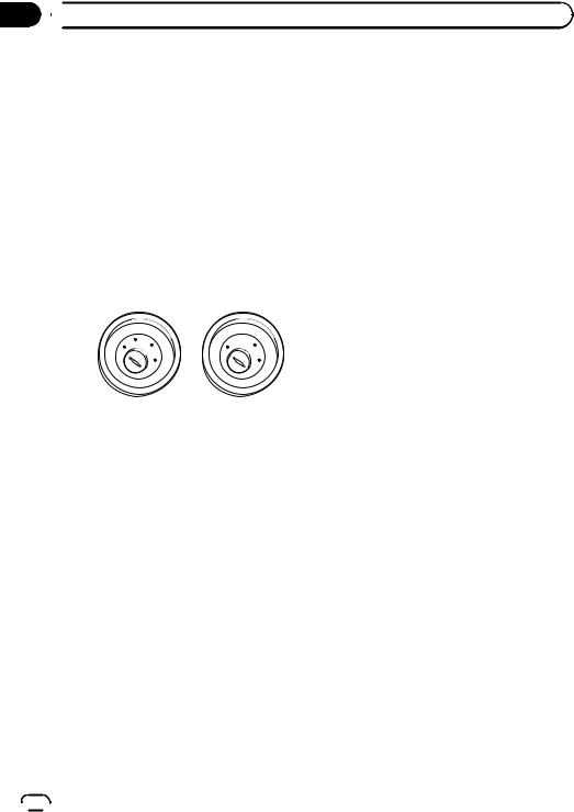
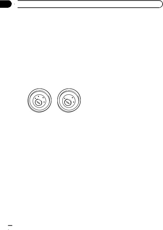
!This product cannot be installed in a vehicle without ACC (accessory) position on the ignition switch.
|
CC |
|
|
|
F |
A |
O |
F |
O |
|
N |
N |
||
F |
|
|
F |
|
O |
|
|
O |
|
|
|
S |
|
S |
|
|
T |
|
T |
|
|
A |
|
A |
|
|
T |
|
T |
ACC position |
No ACC position |
|||
!To avoid short-circuiting, cover the disconnected lead with insulating tape. It is especially important to insulate all unused speaker leads, which if left uncovered may cause a short circuit.
!Refer to the owner’s manual for details on connecting the power amp and other units, then make connections accordingly.
!Since a unique BPTL circuit is employed, do not directly earth the * side of the speaker lead or connect the * sides of the speaker leads together. Be sure to connect the * side of the speaker lead to the * side of the speaker lead on this navigation system.
!If the RCA pin jack on this product will not be used, do not remove the caps attached
to the end of the connector.
Notice for the blue/white lead
!When the ignition switch is turned on (ACC ON), a control signal is output through the blue/white lead. Connect to an external power amp’s system remote control terminal, the auto-aerial relay control terminal, or the aerial booster power control terminal (max. 300 mA 12 V DC). The control signal is output through the blue/white lead, even if the audio source is switched off.
!Be sure not to use this lead as the power supply lead for the external power amps. Such connection could cause excessive current drain and malfunction.
!Be sure not to use this lead as the power supply lead for the auto-aerial or aerial booster. Such connection could cause excessive current drain and malfunction.
Notice for the violet/white lead
!The violet/white lead must be connected so that the navigation system can detect whether the vehicle is moving forwards or backwards. Connect the violet/white lead to the lead whose voltage changes when the reverse gear is engaged. Unless connected, the sensor may not detect your vehicle travelling forwards/backwards properly, and thus your vehicle position as detected by
the sensor may not correspond to the actual position.
 6
6 Engb
Engb

 Connecting the system
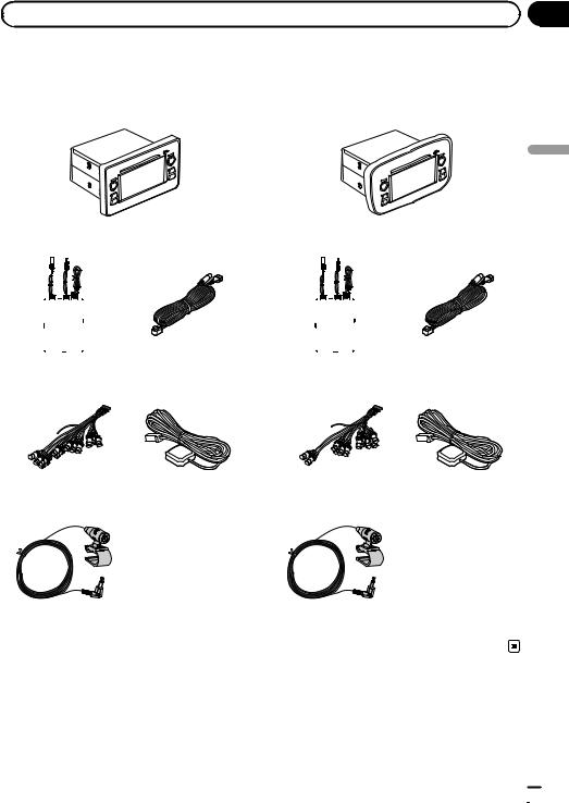
Parts supplied
AVIC-F9210BT |
AVIC-F9220BT |
|
|
|
|
|
|
|
|
Navigation unit |
|
|
|
|
|
|
|
Navigation unit |
|
|
|
|
|
|
|
|
|
|
|
|
|
|
|
|
|
|
|
|
|
|
|
|
|
|
|
|
|
|
|
|
|
|
|
|
|
|
|
|
|
|
|
|
|
|
|
|
|
|
|
Section
03
English
RDS-TMC tuner |
USB and mini-jack |
RDS-TMC tuner |
USB and mini-jack |
|
connector |
|
connector |
RCA connector |
GPS aerial |
RCA connector |
GPS aerial |
Microphone |
Microphone |
Engb  7
7
Section
03 Connecting the system Connecting the system
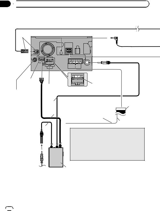
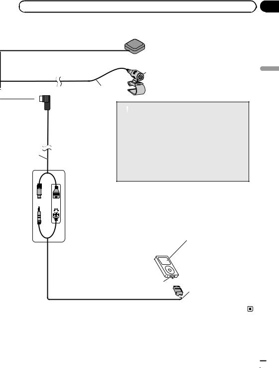
 3.55 m
Green |
Navigation unit |
|
|
|
|
|
|
|
|
|
|
 Aerial jack
Expansion port
WIRED REMOTE INPUT
Please see the Instruction Manual for the Wired Remote Control Adapters (sold separately).
Fuse (10 A)
Power cord
For connection, refer to the wiring and installation manual separately supplied.
30 cm
|
Yellow/black |
RCA connector |
|
|
|
|
If you use an equipment with mute |
|
1 m |
function, connect that equipment to the |
|
|
Audio Mute lead. If not, keep this lead free |
|
|
of any connections. |
|
|
|
15 cm |
30 cm
 Note
Note
Audio source will be set to mute or attenuate, while the following sounds will not be muted or attenuated. For details,
see Operation Manual.
— voice guidance of the navigation
—incoming ringtone and incoming voice of the mobile phone that is connected to this navigation system via
Bluetooth wireless technology
RDS-TMC tuner
Vehicle aerial
 8
8 Engb
Engb

|
Section |
Connecting the system |
03 |
|
English |
|
GPS aerial |
Microphone
4 m
 USB and mini-jack connector
2 m
(*1)
Connect either the USB Interface Cable for iPod or an appropriate USB storage device.
 WARNING
·To avoid the risk of accident and the potential violation of applicable laws, this product should never be used while the vehicle is being driven except for navigation purposes. And, also Rear Displays should not be in a location where it is a visible distraction to the driver.
·In some countries, the viewing of images on a display inside a vehicle even by persons other than the driver may be illegal. Where such regulations apply they must be obeyed and this product’s video source should not be used.
|
|
(*2) |
|
|
|
|
|
|
|
|
|
|
(*1) |
— When connecting your iPod, both |
|
connections are necessary. |
|
|
|
|
|
|
— It is necessary to set “AV1 Input” |
(*2) |
|
in “AV System Settings” to “iPod” |
|
when connecting the iPod. (For |
|
|
|
|
|
|
details, refer to Operation Manual.) |
Dock  connector
  port
port 

iPod with
Dock connector(*3)
(*3)
For details concerning operations and compatibility , refer to Operation Manual.
USB Interface Cable for iPod (CD-IU50V) (sold separately)
Engb  9
9

Section
03  Connecting the system
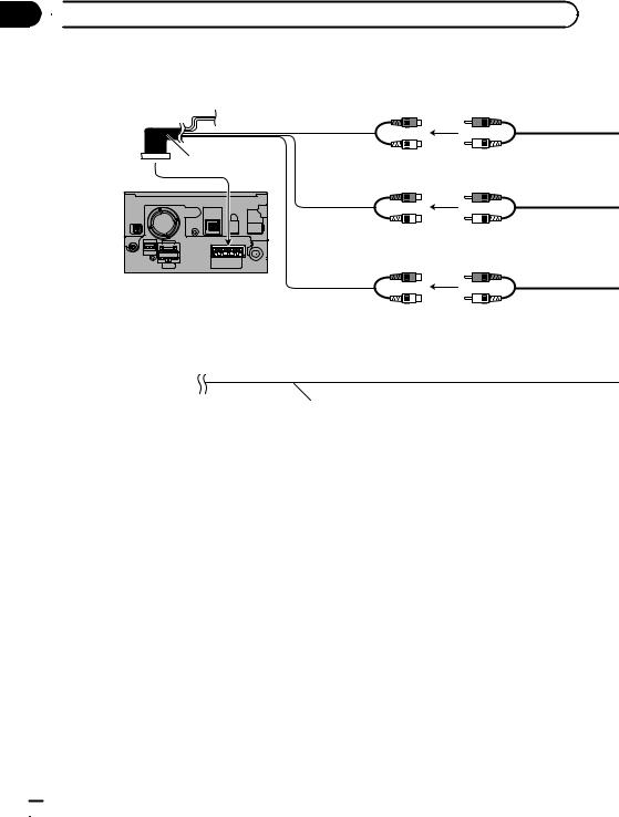
When connecting to separately sold power amp
Subwoofer output (SUBWOOFER OUTPUT)
31 cm
RCA connector
Rear output (REAR OUTPUT)
15 cm
Front output (FRONT OUTPUT)
Navigation unit
15 cm
 Blue/white
To system control terminal of the power amp (max. 300 mA 12 V DC).
For connection, refer to the wiring and installation manual separately supplied.
 10
10 Engb
Engb
|
Section |
Connecting the system |
03 |
|
English |
|
Power amp |
|
(sold separately) |
RCA cables (sold separately)
Power amp (sold separately)
Power amp (sold separately)
System remote control |
|
Left |
Right |
|
|
Front speaker |
Front speaker |
|
|
|
|
Rear speaker |
Rear speaker |
|
|
|
|
Subwoofer |
Subwoofer |
|
|
 Note
Note
You can change the RCA output of the subwoofer depending on your subwoofer system. (Refer to Operation Manual.)
Engb  11
11

Section |
|
|
|
|
|
|
|
|
03 |
|
Connecting the system |
|
|
|
|
|
|
|
When connecting a rear |
|
|
|
|
|
|
|
|
Rear view camera |
|
|
|
|
|
||
|
view camera |
(e.g. ND-BC4) |
To video output |
|
|
|
||
|
(sold separately) |
|
|
|
||||
|
When this product is used with a rear view |
|
RCA cable |
|
|
|
|
|
|
camera, it is possible to automatically switch |
|
|
|
|
|
||
|
|
|
|
|
|
|
||
|
from the video to rear view image when the |
|
|
|
|
|
|
|
|
gearstick is moved to REVERSE (R). Rear |
|
Brown |
|
|
|
||
|
View mode also allows you to check what is |
|
(REAR VIEW CAMERA IN) |
|
|
|
||
|
|
|
|
|
||||
|
behind you while driving. |
|
23 cm |
|
|
|
|
|
|
When you use a rear view camera, please be |
|
RCA connector |
|
|
|
||
|
sure to connect the violet/white lead. Other- |
|
|
|
|
|
|
|
|
wise the rear view camera picture will not ap- |
|
|
|
|
|
|
|
|
pear automatically when the vehicle is |
|
|
|
|
|
|
|
|
reversing. |
|
|
|
|
|
|
|
 WARNING
USE INPUT ONLY FOR REVERSE OR MIRROR IMAGE REAR VIEW CAMERA. OTHER USE MAY RESULT IN INJURY OR DAMAGE.
 CAUTION
!The screen image may appear reversed.
!The rear view camera function is to use this product as an aid to keep an eye on trailers, or backing into a tight parking spot. Do not use this function for entertainment purposes.
!The object in rear view may appear closer or more distant than in reality.
!Please note that the edges of the rear view camera images may differ slightly according to whether full screen images are displayed when backing, and whether the images are used for checking the rear when the vehicle is moving forward.
Navigation unit
 Notes
Notes
!It is necessary to set “Camera” in “Back Camera Settings” to “On” when connecting the rear view camera. (For details, refer to Operation Manual.)
!Connect to the rear view camera. Do not connect to any other equipment.
 12
12 Engb
Engb
 Connecting the system
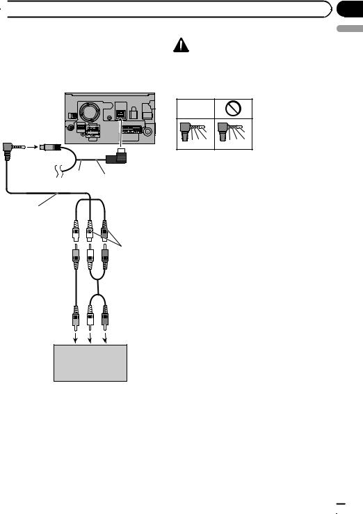
When connecting the |
CAUTION |
|
external video component |
||
Be sure to use a CD-RM10 (sold separately) for |
||
Using “AV1 Input” (AV1) |
wiring. If you use other cables, there is a case |
|
where wiring position differs, images and sounds |
||
|
||
Navigation unit |
may be disturbed. |
Section
03
English
OK |
|
L |
L |
V G R |
R G V |
L : Left audio (White) R : Right audio (Red) V : Video (Yellow)
G : Earth
2 m
USB and
mini-jack connector
CD-RM10
(sold separately)
Yellow 

Red, white
RCA cables (sold separately)
To video output |
To audio outputs |
External video component (sold separately)
!It is necessary to set “AV1 Input” in “AV Settings” to “Video” when connecting the external video component. (For details, refer to Operation Manual.)
Engb  13
13

Section
03  Connecting the system
Using “AV2 Input” (AV2) |
When connecting the rear |
Navigation unit |
display |
|
Navigation unit |
23 cm
|
|
15 cm |
RCA connector |
|
|
|
Red, white |
RCA connector |
Yellow |
(AUDIO INPUT) |
|
|
|
|
(VIDEO INPUT) |
|
|
|
|
Yellow |
|
|
(REAR MONITOR |
|
|
OUTPUT) |
|
RCA cables |
|
|
(sold separately) |
RCA cable |
|
|
|
|
|
(sold separately) |
To video output |
To audio outputs |
|
|
|
To video input |
|
External video |
|
|
component |
|
|
(sold separately) |
Rear display with |
|
|
|
|
|
RCA input jacks |
!It is necessary to set “AV2 Input” in “AV Settings” to “Video” when connecting the
external video component. (For details, refer to Operation Manual.)
When using a rear display connected to rear video output
 WARNING
NEVER install the rear display in a location that enables the driver to watch the video source while driving.
This navigation system’s rear video output is for connection of a display to enable passengers in the rear seats to watch the video source.
 14
14 Engb
Engb
Precautions before |
buttons or (iii) impair the driver’s ability |
||
installation |
to safely operate the vehicle. |
||
! Install the navigation system between the |
|||
|
|
||
|
CAUTION |
driver’s seat and front passenger seat so |
|
! |
that it will not be hit by the driver or pas- |
||
Never install this product in places where, |
|||
senger if the vehicle stops quickly. |
|||
|
or in a manner that: |
||
|
! Never install the navigation system in |
||
|
— It could injure the driver or passengers |
||
|
front of or next to the place in the dash, |
||
|
if the vehicle stops suddenly. |
||
|
door, or pillar from which one of your vehi- |
||
|
— It may interfere with the driver’s opera- |
||
|
cle’s airbags would deploy. Please refer to |
||
|
tion of the vehicle, such as on the floor |
||
|
your vehicle’s owner’s manual for refer- |
||
|
in front of the driver’s seat, or close to |
||
|
ence to the deployment area of the frontal |
||
|
the steering wheel or gearstick. |
||
|
airbags. |
||
! |
Make sure there is nothing behind the |
||
|
|||
|
dashboard or panelling when drilling |
|
|
|
holes in them. Be careful not to damage |
To guard against |
|
|
fuel lines, brake lines, electronic compo- |
||
|
nents, communication wires or power |
electromagnetic interference |
|
|
cables. |
In order to prevent interference, set the follow- |
|
! |
When using screws, do not allow them to |
||
ing items as far as possible from this naviga- |
|||
|
come into contact with any electrical lead. |
||
|
tion system, other cables or leads: |
||
|
Vibration may damage wires or insulation, |
||
|
! FM, MW/LW aerial and its lead |
||
|
leading to a short circuit or other damage |
||
|
! GPS aerial and its lead |
||
|
to the vehicle. |
||
|
In addition you should lay or route each aerial |
||
! |
To ensure proper installation, use the sup- |
||
lead as far as possible from other aerial leads. |
|||
Installation
plied parts in the manner specified. If any
parts other than the supplied ones are
Do not bind them together, lay or route them
used, they may damage internal parts of
together, or cross them. Such electromagnetic
this product or they may work loose and
noise will increase the potential for errors in
the product may become detached.
the location display. 
!It is extremely dangerous to allow the cables to become wound around the steer-
ing column or gearstick. Be sure to install |
Before installing |
this product, its cables, and wiring away |
! Consult with your nearest dealer if installa- |
in such a way that they will not obstruct |
tion requires the drilling of holes or other |
or hinder driving. |
modifications of the vehicle. |
! Make sure that leads cannot get caught in |
! Before making a final installation of this |
a door or the sliding mechanism of a seat, |
product, temporarily connect the wiring to |
resulting in a short circuit. |
confirm that the connections are correct |
! Please confirm the proper function of |
and the system works properly. |
your vehicle’s other equipment following |
|
installation of the navigation system. |
|
! Do not install this navigation system |
|
where it may (i) obstruct the driver’s vi- |
|
sion, (ii) impair the performance of any of |
|
the vehicle’s operating systems or safety |
|
features, including airbags, hazard lamp |
|
Section
04
English
Engb  15
15

Section
04  Installation
Installing the navigation |
! When installing, to ensure proper heat dis- |
|||||
system |
persal when using this unit, make sure you |
|||||
leave ample space behind the rear panel |
||||||
|
||||||
Installation notes |
and wrap any loose cables so they are not |
|||||
! Do not install the navigation system in |
blocking the vents. |
|||||
|
|
|
|
|
||
places subject to high temperatures or hu- |
|
|
Dashboard |
|||
midity, such as: |
|
|
|
|
|
|
|
|
5 cm |
||||
— Places close to a heater, vent or air con- |
|
|
||||
|
|
|
|
|
||
ditioner. |
|
|
|
|
|
|
—Places exposed to direct sunlight, such as on top of the dashboard.
— Places that may be exposed to rain, |
|
|
|
|
|
|
|
|
|
||
|
10 cm |
||||
such as close to the door or on the vehi- |
|
||||
|
|
|
|
||
cle’s floor. |
|
|
|
|
|
|
|
|
|
||
! Install this navigation system in an area |
|
|
Leave ample space |
||
strong enough to bear its weight. Choose a |
! The cords must not cover up the area |
||||
position where this navigation system can |
|||||
shown in the figure below. This is neces- |
|||||
be firmly installed, and install it securely. If |
|||||
sary to allow the amps and navigation me- |
|||||
this navigation system is not securely in- |
|||||
chanism to dissipate heat. |
|||||
stalled, the current location of the vehicle |
|||||
|
|
|
|
||
cannot be displayed correctly. |
|
|
|
|
|
!Install the navigation unit horizontally on a surface within 0 degrees to 30 degrees tolerance (within 5 degrees to the left or
right). Improper installation of the unit with |
|
||
the surface tilted more than these toler- |
|
||
ances increases the potential for errors in |
|
||
the location display, and might otherwise |
Do not cover this area. |
||
cause reduced display performance. |
|||
! The semiconductor laser will be damaged |
|||
|
|
||
|
|
if it overheats, so don’t install the naviga- |
|
|
|
tion unit anywhere hot —for instance, near |
|
|
|
a heater outlet. |
|
30° |
|
|
|
5° |
5° |
|
|
 16
16 Engb
Engb
 Installation
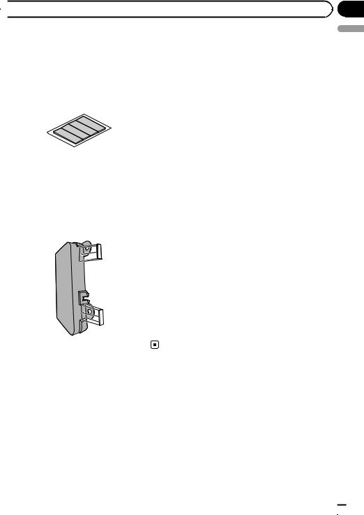
Concealing the metal brackets
For AVIC-F9210BT users
Use the supplied self-adhesive sheets to hide the metal brackets inside that are visible from the front panel slits.
Self-adhesive sheet (4 pcs.)
1Peel the release paper off the sheets.
2Attach the sheets at the top and bottom on both sides of the panel as illustrated below.
Section
04
English
Engb  17
17
Section
04  Installation
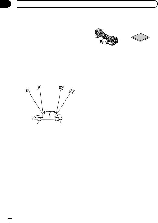
Installing the GPS aerial |
Parts supplied |
 CAUTION
Do not cut the GPS aerial lead to shorten it or use an extension to make it longer. Altering the aerial cable could result in a short circuit or malfunction and permanent damage to the navigation system.
GPS aerial |
Metal sheet |
Installation notes
!The aerial should be installed on a level surface where radio waves will be blocked as little as possible. Radio waves cannot be received by the aerial if reception from the satellite is blocked.
|
|
|
|
|
Dashboard |
|
|
Rear shelf |
|
!When installing the GPS aerial inside the vehicle, be sure to use the metal sheet provided with your system. If this is not used, the reception sensitivity will be poor.
!Do not cut the accessory metal sheet. This would reduce the sensitivity of the GPS aerial.
!Take care not to pull the aerial lead when removing the GPS aerial. The magnet attached to the aerial is very powerful, and the lead may become detached.
!Do not paint the GPS aerial, as this may affect its performance.
 18
18 Engb
Engb
|
Section |
Installation |
04 |
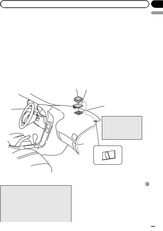
When installing the aerial inside the vehicle (on the dashboard or rear shelf)
 WARNING
Do not install the GPS aerial over any sensors or vents on the dashboard of the vehicle, as doing so may interfere with the proper functioning of such sensors or vents and may compromise the ability of the metal sheet under the GPS aerial to properly and securely affix to the dashboard.
Affix the metal sheet on as level a surface as possible where the GPS aerial faces the window. Place the GPS aerial on the metal sheet. (The GPS aerial is fastened with its magnet.)
GPS aerial
 Notes
Notes
!When attaching the metal sheet, do not cut it into small pieces.
!Some models use window glass that does not allow signals from GPS satellites to pass through. On such models, install the GPS aerial on the outside of the vehicle.
Metal sheet
Peel off the protective sheet on the rear.
Make sure the surface is free of moisture, dust, grime, oil, etc., before affixing the metal sheet.
 Note
Note
The metal sheet contains a strong adhesive which may leave a mark on the surface if it is removed.
Clamps
Use separately sold clamps
to secure the lead where necessary inside the vehicle.
English
Engb  19
19
Section
04  Installation
Installing the microphone |
2 Attach the microphone clip to the sun |
|
! Install the microphone in a place where its |
visor. |
|
Microphone clip |
||
direction and distance from the driver |
||
make it easiest to pick up the driver’s voice. |
|
|
! Make sure to connect the microphone to |
|
|
the navigation system after the system is |
|
|
turned off. (ACC OFF) |
|
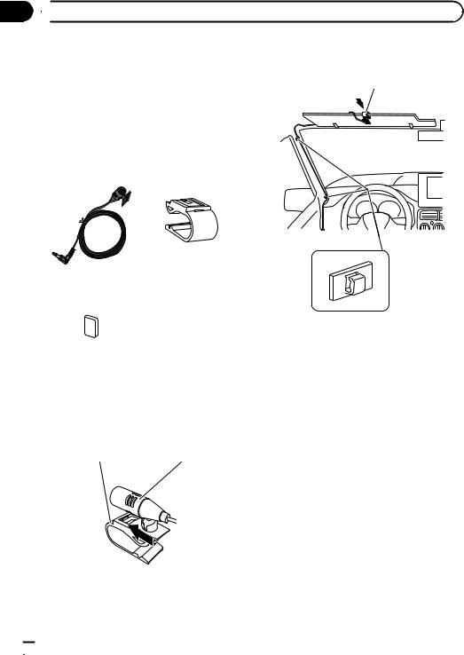
Parts supplied
Microphone |
Microphone clip |
Double-sided tape
Mounting on the sun visor
1 Install the microphone in the microphone clip.
Microphone clip |
Microphone |
Clamps
Use separately sold clamps to secure the lead where necessary inside the vehicle.
Install the microphone on the sun visor when it is in the up position. It cannot recognise the driver’s voice if the sun visor is in the down position.
 20
20 Engb
Engb
|
Section |
Installation |
04 |
Installation on the steering column |
Adjusting the microphone angle |
% Mount the microphone on the steering |
The microphone angle can be adjusted. |
column. |
|
Double-sided tape |
|
Install the microphone on the steering column, keeping it away from the steering wheel.
Clamps
Use separately sold clamps to secure the lead where necessary inside the vehicle.
English
Engb  21
21


 Índice
 INFORMACIÓN IMPORTANTE
ACERCA DE SU NUEVO SISTEMA DE NAVEGACIÓN Y ESTE MANUAL 23
 PRECAUCIONES IMPORTANTES
LEA TODAS ESTAS INSTRUCCIONES RELACIONADAS CON SU SISTEMA DE NAVEGACIÓN Y GUÁRDELAS PARA EMPLEARLAS COMO REFERENCIA EN EL FUTURO 24
 Conexión del sistema
Precauciones antes de conectar el sistema 25
Antes de instalar este producto 25 Para impedir daños 26
–Aviso para el cable conductor azul/ blanco 26
–Aviso para el cable conductor violeta/ blanco 26
Partes suministradas 27
–AVIC-F9210BT 27
–AVIC-F9220BT 27
Conexión del sistema 28
Conexión al amplificador de potencia que se
vende por separado 30 |
|
|
Conexión de una cámara para visión |
|
|
trasera |
32 |
|
Al conectar el componente de vídeo |
|
|
externo |
33 |
|
– Utilización de “Entrada AV1” (AV1) |
33 |
|
– Utilización de “Entrada AV2” (AV2) |
34 |
|
Al conectar la pantalla posterior 34 |
|
|
–Al usar una pantalla posterior conectada a la salida de vídeo trasera 34
Instalación |
|
Precauciones antes de la instalación |
35 |
Para impedir que se produzcan |
|
interferencias electromagnéticas |
35 |
Antes de la instalación 36 |
|
Instalación del sistema de navegación |
36 |
|
– Notas acerca de la instalación |
36 |
|
Cómo ocultar los soportes metálicos |
37 |
|
Instalación de la antena GPS |
38 |
|
– Notas acerca de la instalación |
38 |
|
– Partes suministradas |
38 |
|
–Cuando instale la antena en el interior del vehículo (en el salpicadero o en la bandeja trasera) 39
Instalación del micrófono |
40 |
|
– |
Partes suministradas |
40 |
– |
Montaje en el parasol |
40 |
– |
Instalación en la columna de |
|
|
dirección 41 |
|
– |
Ajuste del ángulo del micrófono 42 |
|
 22
22 Es
Es

|
Sección |
INFORMACIÓN IMPORTANTE |
01 |
ACERCA DE SU NUEVO |
hículo o a la forma del interior del |
SISTEMA DE NAVEGACIÓN Y |
vehículo. |
|
|
ESTE MANUAL |
|
!Las funciones de navegación de este producto (y de la opción de cámara para visión trasera si se ha adquirido) están pensadas únicamente para ayudarle en el manejo de su vehículo. De ninguna forma deben considerarse como un sustituto de su atención, buen juicio y cuidado durante la conducción.
!Nunca utilice este sistema de navegación para guiarse hasta hospitales, comisarías de policía o instalaciones parecidas si se produce una emergencia. En tal caso, llame al número de emergencias correspondiente.
!No utilice el sistema de navegación (o la opción de cámara para visión trasera, si dispone de ella) si le puede distraer o impedir que conduzca de manera segura. Cumpla siempre las normas de seguridad para la conducción y respete todas las regulaciones de tráfico existentes. Si tiene problemas al manejar el sistema o al leer la pantalla, aparque el vehículo en un lugar seguro y ponga el freno de mano antes de realizar los ajustes necesarios.
!Este manual explica cómo instalar este sistema de navegación en su vehículo. Sin embargo, en el manual de instalación independiente se describe parte del proceso de cableado e instalación. El funcionamiento de este sistema de navegación se explica en un manual independiente.
!No instale este producto en puntos en los que pueda (i) dificultar la visión del conductor, (ii) comprometer el funcionamiento de alguno de los sistemas de seguridad del vehículo, como los airbags, los botones de los indicadores de peligro, o (iii) comprometer la capacidad del conductor para manejar el vehículo con seguridad. En algunos casos, es posible que este producto no pueda instalarse debido al tipo de ve-
Español
Es  23
23

Sección
02  PRECAUCIONES IMPORTANTES
 ADVERTENCIA
Pioneer aconseja que no realice usted mismo la instalación del sistema de navegación. Recomendamos que sólo el personal de servicio autorizado de Pioneer, que cuenta con formación especializada y experiencia en el campo de la electrónica móvil, instale y configure este producto. NUNCA EFECTÚE EL MANTENIMIENTO DE ESTE PRODUCTO USTED MISMO. La instalación o el mantenimiento del producto y de los cables de conexión asociados puede exponerle al riesgo de una descarga eléctrica u otros peligros, y puede ocasionar daños en el sistema de navegación que no cubre la garantía.
LEA TODAS ESTAS
INSTRUCCIONES RELACIONADAS CON SU SISTEMA DE NAVEGACIÓN Y GUÁRDELAS PARA EMPLEARLAS COMO REFERENCIA EN EL FUTURO
1Lea completa y detenidamente este manual antes de instalar su sistema de navegación.
2Guarde al alcance de la mano este manual para utilizarlo como referencia en el futuro.
3Ponga mucha atención a todas las advertencias de este manual y siga cuidadosamente las instrucciones.
4En ciertas circunstancias, este sistema de navegación puede mostrar una información errónea de la posición de su vehículo, la distancia de los objetos mostrados en la pantalla y las direcciones de la brújula. Además, el sistema tiene ciertas limitaciones, incluyendo la incapacidad de identificar calles de una dirección, restricciones temporales de tráfico y zonas donde la conducción pueda resultar peligrosa. Haga uso de su buen juicio en función de las condiciones de conducción reales.
5Al igual que con cualquier otro accesorio del interior, el sistema de navegación nunca deberá distraerle ni poner en peligro el manejo seguro de su vehículo. Si encuentra dificultades al utilizar el sistema o al leer la pantalla, haga los ajustes necesarios con el vehículo estacionado en un lugar seguro.
6Recuerde ponerse siempre el cinturón de seguridad cuando maneje su vehículo. En el caso de sufrir un accidente, sus lesiones pueden ser mucho más graves si no tiene bien puesto su cinturón de seguridad.
7Algunos países y leyes gubernamentales pueden prohibir o limitar la ubicación y el uso de este sistema en su vehículo. Cumpla con todas las leyes y normas pertinentes en cuan-
to al uso, la instalación y el funcionamiento del sistema de navegación.
 24
24 Es
Es
Sección
 Conexión del sistema
Precauciones antes de |
! Nunca suministre alimentación a otros |
|||
conectar el sistema |
productos electrónicos cortando el aisla- |
|||
miento del cable de alimentación del sis- |
||||
|
||||
PRECAUCIÓN |
tema de navegación y tomando corriente |
|||
de él. La capacidad nominal del cable se |
||||
! Si decide efectuar la instalación usted |
||||
excederá y causará un recalentamiento. |
||||
mismo y cuenta con formación especiali- |
||||
|
|
|
||
zada y experiencia en la instalación de sis- |
|
|
|
|
temas electrónicos móviles, siga con |
Antes de instalar este |
|||
cuidado todos los pasos descritos en el |
||||
manual de instalación. |
producto |
|||
! Asegure todo el cableado con abrazaderas |
! Utilice esta unidad solamente con una ba- |
|||
de cables o cinta para usos eléctricos. No |
||||
tería de 12 voltios y puesta a tierra negativa. |
||||
permita que el cableado pelado perma- |
||||
De lo contrario, podrá ocasionar un incen- |
||||
nezca descubierto. |
||||
dio o un fallo de funcionamiento. |
||||
! Es extremamente peligroso permitir que |
||||
! Para evitar cortocircuitos en el sistema |
||||
los cables queden enrollados alrededor de |
||||
eléctrico, asegúrese de desconectar el |
||||
la columna de la dirección o palanca de |
||||
cable de la batería (–) antes de comenzar |
||||
cambio. Asegúrese de instalar este pro- |
||||
con la instalación. |
||||
ducto, sus cables y hilos alejados, de |
||||
|
|
|
||
forma que no obstruyan o impidan la con- |
|
|
|
|
ducción del vehículo. |
|
|
|
|
! Asegúrese de que todos los cables estén |
|
|
|
|
enrutados y sujetos de manera que no en- |
|
|
|
|
torpezcan o queden atrapados con alguna |
|
|
|
|
de las partes móviles del vehículo, en es- |
|
|
|
|
|
|
|
||
pecial con el volante, la palanca de cam- |
|
|
|
|
bio, el freno de mano, las guías de los |
|
|
|
|
asientos deslizantes, las puertas o con al- |
|
|
|
|
guno de los controles del vehículo. |
|
|
|
|
!No enrute cables que vayan a estar sometidos a altas temperaturas. Si se calienta el aislamiento, los cables pueden resultar dañados y, como consecuencia, puede producirse un cortocircuito o una avería y el producto puede sufrir un deterioro permanente.
!No corte el cable de la antena GPS para reducir su longitud ni utilice una extensión para alargarlo. La alteración del cable de la antena puede causar un cortocircuito.
!No acorte ningún cable. En el caso de que lo haga, el circuito de protección (el portafusibles, la resistencia de fusible o el filtro, etc.) puede que no funcione correctamente.
03
Español
Es  25
25
Sección
03  Conexión del sistema
Para impedir daños
 ADVERTENCIA
!Utilice altavoces con capacidad superior a 50 W (valor de salida) y entre 4 W a 8 W
(valor de impedancia). No utilice altavoces de 1 W a 3 W para esta unidad.
!Al sustituir el fusible, asegúrese de utilizar exclusivamente un fusible del régimen nominal descrito en este producto.
!Cuando desconecte un conector, tire del propio conector. No tire del cable porque podría sacarlo del conector.
!No se puede instsalar este producto en un vehículo sin la posición ACC (accesorio) en el interruptor de encendido.
|
CC |
|
|
|
F |
A |
O |
F |
O |
|
N |
N |
||
F |
|
|
F |
|
O |
|
|
O |
|
|
|
S |
|
S |
|
|
T |
|
T |
|
|
A |
|
A |
|
|
T |
|
T |
Posición ACC |
Sin posición ACC |
|||
!Para evitar cortocircuitos, cubra el conductor desconectado con cinta aislada. Es especialmente importante aislar todos los cables de altavoz que no se usen, ya que si no se recubren pueden llegar a provocar un cortocircuito.
!Consulte el manual del propietario para obtener información sobre la conexión del amplificador de potencia y de otras unidades y, a continuación, realice las conexiones de manera acorde.
!Como se utiliza un circuito BPTL único, no conecte directamente a tierra el extremo * del cable del altavoz, ni conecte juntos los extremos * de los cables de los altavoces. Asegúrese de conectar el extremo * del cable del altavoz al extremo * del cable del altavoz de este sistema de navegación.
!Si no va a utilizarse la clavija RCA en este producto, no retire las tapas del extremo
del conector.
Aviso para el cable conductor azul/blanco
!Al conectar el interruptor de encendido (ACC ON), se envía una señal de control por el cable azul/blanco. Conéctelo al terminal de control remoto del sistema externo de amplificadores de potencia, al terminal de control de relé de la antena automática, o al terminal de control de potencia del amplificador de antena (máx. 300 mA 12 V CC). La señal de control se envía por el cable azul/blanco, aunque la fuente de audio esté desconectada.
!Asegúrese de utilizar este cable conductor como el cable conductor del suministro de energía para los amplificadores de potencia externos. Tal conexión podría causar un drenaje excesivo de corriente y un fallo de funcionamiento.
!Asegúrese de utilizar este cable conductor como el cable conductor del suministro de energía para la antena automática o amplificador de antena. Tal conexión podría causar un drenaje excesivo de corriente y un fallo de funcionamiento.
Aviso para el cable conductor violeta/blanco
!El cable violeta/blanco debe conectarse para que el sistema de navegación pueda detectar si el vehículo se está desplazando hacia detrás o hacia delante. Conecte el cable violeta/blanco al cable cuyo voltaje cambia cuando se sitúa la palanca de cambios en la posición de marcha atrás. A menos que esté conectado, el sensor podría no detectar si su vehículo está desplazándose hacia detrás o hacia delante correctamente, por lo que la posición del
vehículo que detecta el sensor podría no corresponder a la posición real.
 26
26 Es
Es
|
Sección |
Conexión del sistema |
03 |
Partes suministradas |
|
AVIC-F9210BT |
AVIC-F9220BT |
Español
|
|
|
|
|
|
Unidad de navegación |
|
|
|
|
|
Unidad de navegación |
||||
|
|
|
|
|
|
|
|
|
|
|
|
|
|
|
|
|
|
|
|
|
|
|
|
|
|
|
|
|
|
|
|
|
|
|
|
|
|
|
|
|
|
|
|
|
|
|
|
|
|
|
Sintonizador RDS-TMC |
Conector USB y |
Sintonizador RDS-TMC |
Conector USB y |
|
minijack |
|
minijack |
Conector RCA |
Antena GPS |
Conector RCA |
Antena GPS |
Micrófono |
Micrófono |
Es  27
27

Sección
03 Conexión del sistema Conexión del sistema
 3,55 m
Unidad de navegación
Verde
 Toma de antena
Puerto de expansión
WIRED REMOTE INPUT
Consulte el Manual de instrucciones para los adaptadores de control remoto alámbrico (se venden por separado).
Fusible (10 A)
Cable de alimentación
Para el proceso de conexión, consulte el manual de cableado e instalación independiente suministrado.
30 cm
|
Amarillo/negro |
Conector RCA |
|
|
|
|
Si utiliza un equipo con una función de |
|
1 m |
silencio, conecte ese equipo al cable de |
|
|
silencio de audio. Si no, deje ese cable sin |
|
|
conexión. |
|
|
|
15 cm |
30 cm
 Nota
Nota
La fuente de audio se silenciará o atenuará, mientras que los sonidos siguientes no se silenciarán ni atenuarán. Para los
detalles, consulte el Manual de operación.
— guía de voz del sistema de navegación
—timbre entrante y voz entrante del teléfono móvil conectado al sistema de navegación a través de la
tecnología inalámbrica Bluetooth
Antena del vehículo |
Sintonizador RDS-TMC |
|
 28
28 Es
Es
|
Sección |
Conexión del sistema |
03 |
4 m
 Conector USB y minijack
2 m
(*1)
Conecte el cable de interfaz USB para iPod o un dispositivo de almacenamiento USB apropiado.
Antena GPS
Micrófono
 ADVERTENCIA
·Para evitar el riesgo de accidente y la posible violación de las leyes aplicables, nunca se debe utilizar este producto mientras se conduce el vehículo, excepto para la finalidad de navegación. Además, no se debe posicionar la pantalla posterior donde la misma pueda presentar una distracción visible al conductor.
·En algunos países, la visualización de imágenes en una pantalla dentro de un vehículo, aún por los pasajeros, puede ser ilegal. Cuando aplicables, se debe obedecer tales reglamentos y no se debe utilizar la fuente de vídeo de este producto.
Español
|
|
|
|
|
|
|
(*2) |
|
|
||
|
(*1) — Cuando conecte su iPod, ambas |
|
|
conexiones son necesarias. |
|
|
— Al conectar el iPod, se debe ajustar |
|
(*2) |
“Entrada AV1” en “Conf. sistema |
|
AV” a “iPod”. (Para los detalles, |
||
|
||
|
consulte el Manual de operación.) |
Puerto de  conector de
  acoplamiento
iPod con Conector de acoplamiento(*3)
(*3)
Para los detalles sobre las operaciones y la compatibilidad, consulte el Manual de operación.
Cable de interfaz USB para iPod (CD-IU50V) (se vende por separado)
Es  29
29
Sección
03  Conexión del sistema
Conexión al amplificador de potencia que se vende por separado
Salida de altavoz de graves (SUBWOOFER OUTPUT)
31 cm
Conector RCA
Salida trasera (REAR OUTPUT)
15 cm
Salida delantera (FRONT OUTPUT)
Unidad de navegación
15 cm
 Azul/blanco
Al terminal de control del sistema del amplificador de potencia (máx. 300 mA 12 V CC).
Para el proceso de conexión, consulte el manual de cableado e instalación independiente suministrado.
 30
30 Es
Es
 Loading...