


iU22
- 3 -
TABLE OF CONTENTS
THEORY OF OPERATION 1
OPERATIONAL TESTING 2
HARDWARE ACCESS 3
ADJUSTMENTS 4
PREVENTATIVE MAINTENANCE 5
TROUBLESHOOTING 6
DICOM OPTIONS 7
PARTS LIST 8
SYSTEM BLOCK DIAGRAMS Appendix A:
Ultrasound Sales Service Repair Training
1815 Industrial Drive, Suite 100 Stockton, CA 95206
Conquest Imaging
PH: 209-942-2654 FAX: 209-942-2572
Rev3 070208.dms

- 4 -
This Page Intentionally Left Blank
Ultrasound Sales Service Repair Training
1815 Industrial Drive, Suite 100 Stockton, CA 95206
Conquest Imaging
PH: 209-942-2654 FAX: 209-942-2572
Rev3 070208.dms
- 5 -
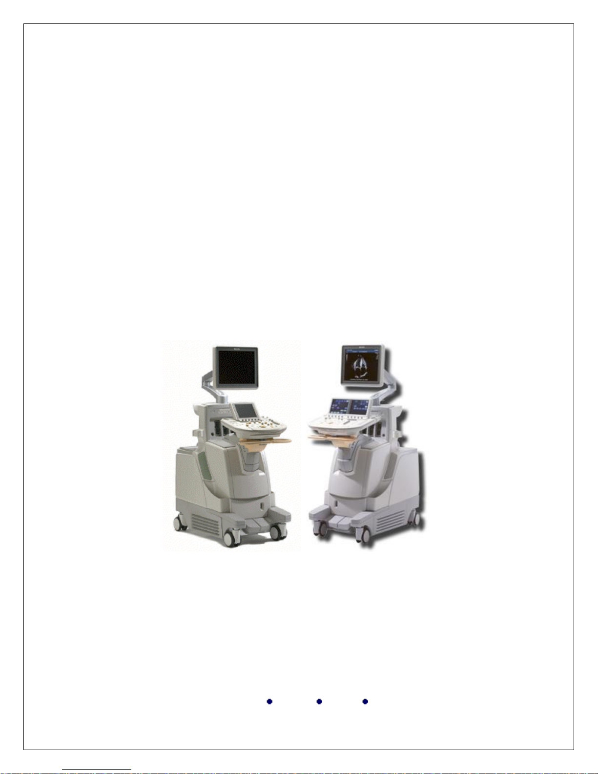
iU22/iE33™
Chapter 1
Theory of Operation
Ultrasound Sales Service Repair Training
1815 Industrial Drive, Suite 100 Stockton, CA 95206
Conquest Imaging
PH: 209-942-2654 FAX: 209-942-2572
Rev3 070208.dms

- 6 -
This Page Intentionally Left Blank
Ultrasound Sales Service Repair Training
1815 Industrial Drive, Suite 100 Stockton, CA 95206
Conquest Imaging
PH: 209-942-2654 FAX: 209-942-2572
Rev3 070208.dms

- 7 -
iU22/iE33™ Theory of Operation
Operating System
The operating system used on the Host and the Signal and Image-Processing
(SIP) motherboards is Microsoft Windows XP Embedded (XP-E). The
embedded XP version allows customization of components and system
behavior. Much of the operating system is hidden from the user, as the
Philips applications use XP-E as a vehicle for implementing system behavior
through custom graphical user interfaces (GUI).
The operating system on the host is primarily used for system interaction
with the user or network and as an application platform for implementing the
iU22 operation and behavior.
The SIP operating system is configured for headless operation (no graphics
subsystem). The primary functions of the SIP operating system include:
Process estimate data to native format data (scan converted but not
scaled to display size)
Process estimate data flow components to sweeping display data and
digital Doppler audio
Process estimate data to M-mode sweeping display data
Implement the Cineloop function for save/recall/review
System Functional Architecture
The Applications layer comprises software to perform administrative
functions and miscellaneous non-imaging tasks necessary to operate the
ultrasound system. The Virtual Ultrasound System comprises all proprietary
technologies developed by Philips that are involved in ultrasound imaging
and the related physiological signals. These include hardware, firmware, and
software. The Platform layer comprises the hardware and infrastructure
required to run the applications and virtual ultrasound systems.
Ultrasound Sales Service Repair Training
1815 Industrial Drive, Suite 100 Stockton, CA 95206
Conquest Imaging
PH: 209-942-2654 FAX: 209-942-2572
Rev3 070208.dms

- 8 -
Signal Flow
Ultrasound data (RF) is acquired from each transducer element and beamformed (summed) into a coherent data stream. This RF data stream is moved
over the RF bus between the Front-End Controller (FEC) and the Host
resident Dual Signal Conditioning (DSC) PCB.
The DSC processes the RF data to estimate space data, commonly referred to
as R-Theta data. This estimate data (2D, Doppler, and so on.) is sent to the
SIP Motherboard to be further processed into each final display data type
supported by the system (2D, 3D, 4D, Doppler, Audio, M-mode, and so on).
The SIP Motherboard stores these data types locally in the SIP hard drive
sub-system (Cineloop images).
From Cineloop images, this data is time-aligned by a streaming data manager
application and provided to Frame Composition processing for composite
image display and real-time annotation. Frame Composition uses the Host
AGP card to compose each image element into a composite display
containing image, text and graphical elements.
Ultrasound Sales Service Repair Training
1815 Industrial Drive, Suite 100 Stockton, CA 95206
Conquest Imaging
PH: 209-942-2654 FAX: 209-942-2572
Rev3 070208.dms
- 9 -
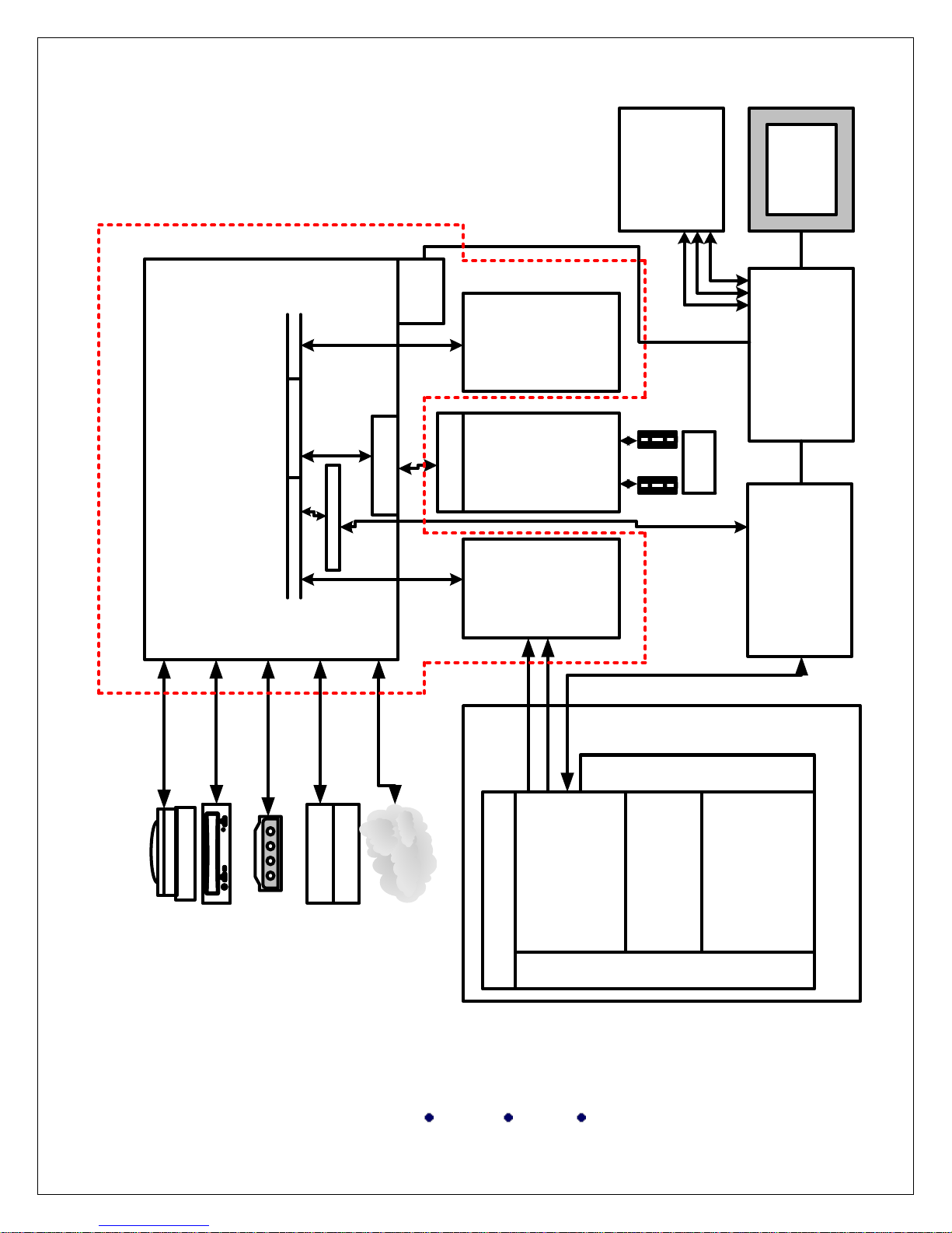
iU 22 Basic Block Diagram
Acquisition Subsystem
Scanhead Select
FEC
AIM+
Channel
Boards
Acquisition Front Plane
Display
OEMs
AVIO RIP
AVIO CAD
IEPSIP
DSC
Hard
Drives
PCI Bus - 64 Bit
PCI Bus - 32 Bit
RFA
RFB
USB
AGP
D V D
DVD drive
Modem
Hard Drive
CP/UIF
External
Network
Motor Control
Dolphin
Dolphin
HOST
Ultrasound Sales Service Repair Training
1815 Industrial Drive, Suite 100 Stockton, CA 95206
PH: 209-942-2654 FAX: 209-942-2572
Conquest Imaging
Rev3 070208.dms

- 10 -
Power Subsystem
Note: The power subsystem used on initially released systems is designated
for “A.x systems.” The subsequently released power subsystem is designated
for “B.0 systems.” Release A.x and B.0 systems are identified by a green or
blue LED, respectively, on the rear of the AC Tray.
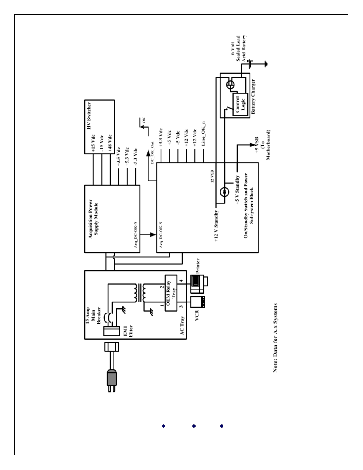
Power Subsytem (A.x Systems)
The A.x power subsystem contains:
Platform Power Supply (PPS)
Platform Power Distribution Board (PPDB) • Acquisition Power
Supply (APS)
AC Tray
HV Switcher (used on A.x and B.0 systems)
Power enters the iU22 system via the AC receptacle, located on the AC Tray.
The AC Tray includes an EMI filter, circuit breaker, OEM isolation
transformer and OEM power relay. AC voltage is also routed to both custom
power supplies (Acquisition and Platform). The Power Subsystem is
controlled by the On/Standby switch, located next to the DVD drive. The
On/Standby switch, in conjunction with the Host Motherboard power control
circuitry generates a PS_ON# signal, which activates the two system power
supplies. The power supplies are interlocked, which controls voltage
application during power up.
The Acquisition and Platform supplies contain monitoring hardware, which
prevent sustained over- or under-voltage or over-current conditions. If one of
the supplies does not meet specification, the Power Subsystem shuts
down.This condition requires the AC mains to be disconnected for at least
one minute to discharge the power supply internal voltages and reset the
fault circuitry. There are no power supply adjustments. The power supplies
are factory set and sealed.
Ultrasound Sales Service Repair Training
1815 Industrial Drive, Suite 100 Stockton, CA 95206
Conquest Imaging
PH: 209-942-2654 FAX: 209-942-2572
Rev3 070208.dms

- 11 -
When the Power Subsystem is in low-power sleep mode, the power supplies
are shut down except for +5STBY, which is required to support motherboard
standby functions. When the system is in standby mode (suspend-to-RAM),
the Host software sets a battery enable register bit on the AVIO-CAD
Module and turns off both power supplies. In this state, the system is
consuming less than 7 W of energy and stays in this state indefinitely while
plugged into the AC mains. The battery enable register bit allows the battery
pack to provide energy to the Platform Power Supply +5STBY circuit if the
AC mains is disconnected.
The maximum duration of the mobile standby state is 4 hours. If the system
is unplugged for more than 4 hours and left in standby, a battery monitoring
circuit senses the battery discharge state and disconnects the battery from
the Platform Power Supply, preventing battery damage. By disconnecting
the battery, the Platform Power Supply can no longer supply +5STBY to
both motherboards, and the system enters a complete power-down state.
Subsequent iU22 power-up executes a cold boot cycle to obtain imaging
operation. Normally, if the system is still in a sus-pend state, the system will
boot much quicker as it is restoring the previous operating system state
saved in RAM. Typical boot times are greater than 2 minutes for a cold boot
and less than 35 seconds for a resume from standby.
The ACQ_DC_OK_n signal line indicates the operating condition of the
Acquisition Power Supply and allows for correct operation of the Platform
Power Supply if the Acquisition Power Supply is not inserted or is inserted
and functioning correctly. It also prevents a false-good indication if the
Acquisition Power Supply fails, including conditions where the input fuses
blow.
The DC_OK_OUT signal line is a reset signal to the system. It is dependent
on the power state of the Acquisition Power Supply and the Platform Power
Supply.
Ultrasound Sales Service Repair Training
1815 Industrial Drive, Suite 100 Stockton, CA 95206
Conquest Imaging
PH: 209-942-2654 FAX: 209-942-2572
Rev3 070208.dms

- 12 -
Battery Charging
A fully-charged system battery should maintain the system in the standby
state for approximately four hours without the system being plugged in. If
the battery has been fully discharged, the system may not boot up until the
system has been plugged in for up to 20 minutes to get a sufficient charge on
the battery.
The system battery is charging when:
The system is powered up and in use
The system is shutdown, the circuit breaker is on, and the power cord
is connected to a power outlet.
The system is in standby, circuit breaker is on, and the power cord is
connected to a power outlet. (During this state, standby is maintained
by current from the power outlet, not the battery.)
The system battery is being discharged when the system is in standby and if
the circuit breaker is off, or if the power cord is not connected to a power
outlet
USB Port Power
The Universal Serial Bus (USB) ports on the back of the DVD drive are
powered by the system battery if the system is off (power switch is off and
the breaker is on). The USB ports are powered by power from the
motherboard. The four USB ports on the rear of the AVIO-RIP and the
USB port for the control panel are powered by system power. If system
power is on, the ports are powered. If the system is off or in standby mode,
there is no power to the USB ports.
Ultrasound Sales Service Repair Training
1815 Industrial Drive, Suite 100 Stockton, CA 95206
Conquest Imaging
PH: 209-942-2654 FAX: 209-942-2572
Rev3 070208.dms
Ultrasound Sales Service Repair Training
- 13 -
1815 Industrial Drive, Suite 100 Stockton, CA 95206
Conquest Imaging
PH: 209-942-2654 FAX: 209-942-2572
Rev3 070208.dms
- 14 -
Ultrasound Sales Service Repair Training
1815 Industrial Drive, Suite 100 Stockton, CA 95206
Conquest Imaging
PH: 209-942-2654 FAX: 209-942-2572
Rev3 070208.dms

- 15 -
Platform Power Supply
The Power Subsystem comprises the following hardware modules:
Platform Power Supply (PPS)
Platform Power Distribution Board
Acquisition Power Supply (APS)
AC Tray
HV Switcher
Platform Power Supply Module
Provides +3.3 Vdc, ±5.0 Vdc, ±12 Vdc, +12 VSB, and +5 VSB. The
+12 VSB is used as a source for the +5 VSB regulator and a source for the
battery charger, located on the AVIO-RIP. The +12 VSB and +5 VSB
are present when AC power is applied. (The iU22 system does not
need to be fully powered up. It needs only to be plugged into the
wall socket with the circuit breaker on.)
Operates between 85 Vac and 264 Vac at 47 to 63 Hz.
Supplies +12 Vdc to video monitor and +3.3 Vdc to touch screen
LCD and +5 Vdc to the touch screen Backlight Inverter.
Thermal, over-voltage, and over-current protected: If temperature,
voltage, or current exceeds the normal range all voltages or currents
shut down. Cycle AC power to reset.
Remote sense for +3.3 Vdc, +5 Vdc, and ground.
Fused primary voltages. The fuses are located under the power supply
cover.
Battery supplies 2.5 A for 5 ms as the current decreases during
power-down.
Battery powers +5 VSB converter, if battery voltage is greater than
+5.88 V, and if the +12 VSB is less than 9 V. When the system is in
this state, the battery is not charged. Battery does not power +5 VSB
converter if +12 VSB is greater than 9 V, and the battery is charged
during this state.\
Generates system reset signal using state of the Acquisition Power
Supply and Platform Power Supply.
Ultrasound Sales Service Repair Training
1815 Industrial Drive, Suite 100 Stockton, CA 95206
Conquest Imaging
PH: 209-942-2654 FAX: 209-942-2572
Rev3 070208.dms

- 16 -
Platform Power Supply functions correctly if the Acquisition Supply
is not inserted or is inserted and functioning correctly. If something
occurs to take the Platform Power Supply down, the Acquisition
Supply also suspends operation. This may happen if the power supply
is working correctly and a voltage goes out on a system PCB.
Platform Power Distribution Board
Mounts to the back wall of the Platform Card Cage and receives
voltages from the Platform Power Supply via bus bars and distributes
to connectors.
Provides a low impedance connection for the Platform Power Supply
outputs.
Contains voltage sense resistors from the Platform Power Supply for
+3.3 Vdc and +5 Vdc
Provides test points and LEDs to indicate that the Platform Supply is
functioning correctly
Acquisition Power Supply Module
Provides +3.5 Vdc, ±5.3 Vdc, ±15 Vdc, and +48 Vdc.
Operates between 85 Vac and 264 Vac at 47 to 63 Hz
Detects AC input voltages (100 to 120 Vac or 220 to 240 Vac).
Thermal, over-voltage, and over-current protected: If temperature,
voltage, or current exceeds the normal range, all voltages or currents
shut down. Cycle AC power to reset.
Remote sense for +3.5 Vdc, ±5.3 Vdc, and ground.
Fused primary voltages: Fuses are under the power supply cover.
If something occurs to take the Acquisition Power Supply down, the
Platform Power Supply also suspends operation. This may happen if the
Acquisition Power Supply is working fine and a voltage goes out on a
system PCB.
Supplies +48 Vdc to the HV Switcher to operate the system front end.
Ultrasound Sales Service Repair Training
1815 Industrial Drive, Suite 100 Stockton, CA 95206
Conquest Imaging
PH: 209-942-2654 FAX: 209-942-2572
Rev3 070208.dms

- 17 -
AC Tray
Filters input voltage and contains a circuit breaker
Supplies line voltage (100, 120, 230, or 240 Vac) to the Platform
Power Supply and Acquisition Power Supply
Supplies line voltage to the OEM transformer and OEM relay for OEM
operation.
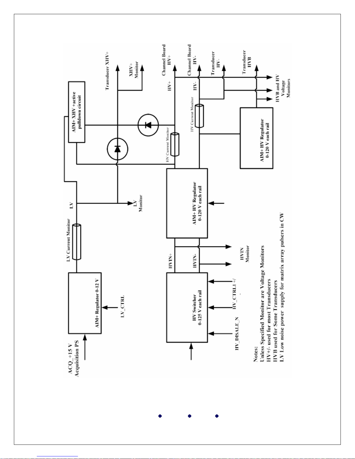
HV Switcher
Converts ±15 Vdc and +48 Vdc from the Acquisition Power Supply to
±HV (±30 to ±120Vdc)
Supplies ±HV to the AIM HV regulators for low-pass filtering to reduce
power supply noise and to the Channel Boards through the Acquisition
Frontplane (for all transmit waveforms except CW)
During CW, turns off power converters supplying ±HV bus and
switches the ±15 Vdc to the ±HV bus
Routes HV to the transducer connector, to provide power for HV
mux devices in the transducer and to power pulsers of the matrix
array
Ultrasound Sales Service Repair Training
1815 Industrial Drive, Suite 100 Stockton, CA 95206
Conquest Imaging
PH: 209-942-2654 FAX: 209-942-2572
Rev3 070208.dms
- 18 -
Ultrasound Sales Service Repair Training
1815 Industrial Drive, Suite 100 Stockton, CA 95206
Conquest Imaging
PH: 209-942-2654 FAX: 209-942-2572
Rev3 070208.dms

- 19 -
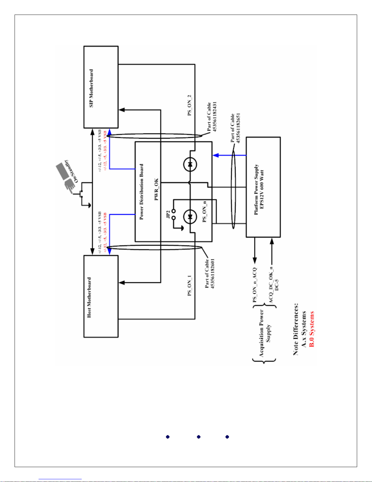
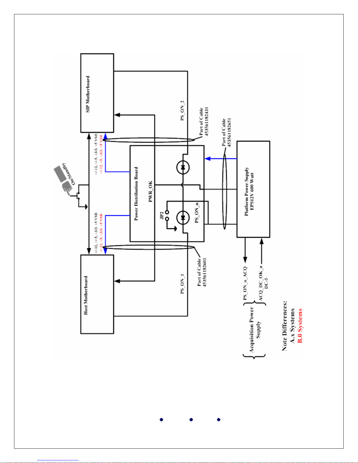
Power Subsytems (B.0/C.0)
The B.0 power subsystem contains:
Power supply assembly
o Platform Power Supply (PPS)
o Acquisition Power Supply (APS)
o Acquisition Power Distribution Board (APDB)
Platform Power Distribution Board (PPDB)
AC Tray
HV Switcher (used on A.x, B.0 and C.0 systems)
Power Theory
Power enters the iU22 system via the AC receptacle, located on the AC
Tray. Power is routed through the circuit breaker, is filtered, and is sent to
the +12 VSB power supply. When the +12 VSB is within regulation, the
system awaits a signal from the operator to start system operation.
Pressing the On/Standby switch initiates a PS_ON_n signal at the Host/SIP
motherboards. The PS_ON_n signal is routed to the Acquisition Power
Distribution Board where it initiates the start-up logic sequence. The startup logic circuitry sends a signal to the AC Tray to close the AC relay,
applying power to the Acquisition Power Supply, the Platform Power Supply, and the OEM power supply. The Acquisition Power Distribution Board
also supplies +5 VSB to the AC Tray to light the blue LED. The +5 VSB is
also on when AC power is off but the battery power is on.
The OEM transformer may be configured for a 120- or 220-Vac input,
depending on whether the OEM transformer primary is wired in series or in
parallel. The OEM power supply in conjunction with the Platform Power
Distribution Board brings all output buses within regulation. Bus
monitoring occurs on the Platform Power Distribution Board and the
Acquisition Power Distribution Board.
Ultrasound Sales Service Repair Training
1815 Industrial Drive, Suite 100 Stockton, CA 95206
Conquest Imaging
PH: 209-942-2654 FAX: 209-942-2572
Rev3 070208.dms

- 20 -
When the monitoring circuits indicate that the buses are within regulation
voltage, a DC_OK_OUT signal is sent from the Acquisition Power
Distribution Board to the Host and SIP motherboards via the Platform
Power Distribution Board. When the motherboards receive this signal, they
initialize and bootup begins.
During system operation, all power buses are monitored by comparators on
the Platform Power Distribution Board. The comparators set the
DC_OK_OUT low if a fault occurs. At the same time, the circuitry on the
Acquisition Power Distribution Board identifies whether the shutdown
signal is coming from the Platform Power Distribution Board or from the
AC tray. The results are displayed with the SPS OK and PPDB OK LEDs
on the Acquisition Power Distribution Board. The LED status is latched
until AC power is removed.
Battery Charging
Same as A.x systems
USB Port Power
Same as A.x systems
Ultrasound Sales Service Repair Training
1815 Industrial Drive, Suite 100 Stockton, CA 95206
Conquest Imaging
PH: 209-942-2654 FAX: 209-942-2572
Rev3 070208.dms
- 21 -
Ultrasound Sales Service Repair Training
1815 Industrial Drive, Suite 100 Stockton, CA 95206
Conquest Imaging
PH: 209-942-2654 FAX: 209-942-2572
Rev3 070208.dms

- 22 -
Power Supply (B.0/C.0) Systems
The power supply assembly comprises the Platform Power Supply Module,
the Acquisition Power Supply Module, and the Acquisition Power
Distribution Board.
Platform Power Supply Module (PPS) (B.0/C.0 Systems)
Supplies +12Vdc to the Platform Power Distribution Board for
conversion to +5 Vdc, +3.3 Vdc, and -12 Vdc.
Operates between 90 and 240 Vac at 45 to 65 Hz.
Thermal, over-voltage, and over-current protected: If
temperature, voltage, or current exceeds the normal range, all
voltages or currents shut down. Cycle AC power to reset.
Fused primary voltages. The fuses are located under the power
supply cover.
Acquisition Power Supply Module (APS) (B.0/C.0 Systems)
Provides +3.5 Vdc, ±5.3 Vdc, ±15 Vdc, and +48 Vdc.
Operates between 85 and 264 Vac at 47 to 63 Hz.
Thermal, over-voltage, and over-current protected: If temperature,
voltage, or current exceeds the normal range, all voltages or currents
shut down. Cycle AC power to reset.
Remote sense for +3.5 Vdc, ±5.3 Vdc, and ground.
Fused primary voltages: Fuses are under the power supply cover.
If something occurs to take the Acquisition Power Supply down, the
Platform Power Supply also suspends operation. This may happen if
the Acquisition Power Supply is working fine and a voltage goes out
on a system PCB.
Supplies +48 Vdc to the HV Switcher to operate the system front end.
Ultrasound Sales Service Repair Training
1815 Industrial Drive, Suite 100 Stockton, CA 95206
Conquest Imaging
PH: 209-942-2654 FAX: 209-942-2572
Rev3 070208.dms

- 23 -
Acquisition Power Distribution Board (APDB) (B.0/C.0 Systems)
Distributes power from the Acquisition Power Supply to the front end
Uses the PS_ON_n signal from the Platform Power Distribution
Board to activate and hold the AC relay on
Monitors +3.65 Vdc, +5.35 Vdc, -5.35 Vdc, +15 Vdc, -15 Vdc, and
+48 Vdc. Creates the APS_DC_OK signal from the monitored
voltages
Uses the APS_DC_OK signal and the PPS_DC_OK signal (from the
Platform Power Supply) to create the SPS_OK signal.
Uses the PLT_PWR_GOOD signal generated on the Platform Power
Distribution Board and the SPS_OK signal to generate the
DC_OK_OUT signal. The DC_OK_OUT signal prevents the Host
and the SIP motherboards from running until all buses are within the
proper voltage range.
Provides fault detection during system operation. If a power supply
fault is detected, a latched-shutdown condition occurs, opening the
AC relay, disabling the power supplies and causing the AC tray LED
to blink. The latched-shutdown condition remains until +12 VSB is
inactive
Provides a power-up time-out interval (approximately 2 to 3 seconds).
If the interval expires, a latched-shutdown condition occurs, opening
the AC relay, disabling the power supplies and causing the AC tray
LED to blink. The latched-shutdown condition remains as long as +12
VSB is active
Enables the Acquisition Power Supply and Platform Power Supply at
system power-up (no delay)
Monitors +5 VSB and illuminates the +5VSB_OK LED if the voltage
is within specifications
Monitors system power-up, shutdown, and fault signals and generates
the appropriate system responses
Twelve LEDs indicate power supply status. Six green LEDs indicate
normal operation. Six red LEDs indicate faults. Refer to Table 9-6 for
LED information
+3.65 Vdc and +5.35 Vdc remote sense signals pass through the
Acquisition Power Distribution Board from the Acquisition Front
Plane to the Acquisition Power Supply
Ultrasound Sales Service Repair Training
1815 Industrial Drive, Suite 100 Stockton, CA 95206
Conquest Imaging
PH: 209-942-2654 FAX: 209-942-2572
Rev3 070208.dms

- 24 -
Platform Power Distribution Board (PPDB) (B.0/C.0 Systems)
Manages the power bus between the Platform Power Supply and
the Platform card cage • Converts +12 Vdc input to +5 Vdc,
+3.3 Vdc, and -12 Vdc
Converts +12 VSB to SW_BATT or to + 5 VSB, depending on
whether the system is in normal operation or in standby
Monitors status of buses and converters and combines the outputs
into one signal (PLT_POWER_GOOD) if the individual outputs
are within specifications
Power-on command provided by PS_ON_n_HOST and
PS_ON_n_SIP signals to become PS_ON_n. This signal is then
sent to the APDB where it is used to activate the AC relay and
hold it on
AC Tray (B.0/C.0 Systems)
Controls AC power to the Acquisition and Platform Power Supplies
by using a board-mounted AC relay. The relay is energized by logic
on the Acquisition Power Distribution Board. The relay controls AC
power to the Acquisition Power Supply, the Platform Power Supply,
and OEM input power.
Configures winding of OEM AC transformer for 90 to 120 Vac, or
220 Vac input power (via two connectors). The AC Trays are sent
correctly configured from the factory.
Provides EMI filtering on AC power lines
Displays power status with a blue LED on the rear of the tray
Generates and routes +12 VSB (standby power) to the Platform
Power Distribution Board
Provides ground lugs for input power and customer equipment
connections
Receives +5 VSB to light the LED from the Acquisition Power
Distribution Board
HV Switcher
Same a A.x
Conquest Imaging
Ultrasound Sales Service Repair Training
1815 Industrial Drive, Suite 100 Stockton, CA 95206
PH: 209-942-2654 FAX: 209-942-2572
Rev3 070208.dms

- 25 -
Power Subsystems (D.0)
The D.0 power subsystem contains:
• Power Supply Assembly
- Platform Power Supply (PPS)
- Acquisition Power Distribution Board (APDB)
- Acquisition Power Supply (APS)
• Battery Thermal Management (BTM) board
• Signal and Power Distribution Board (SPD)
• AC Tray
• HV Switcher
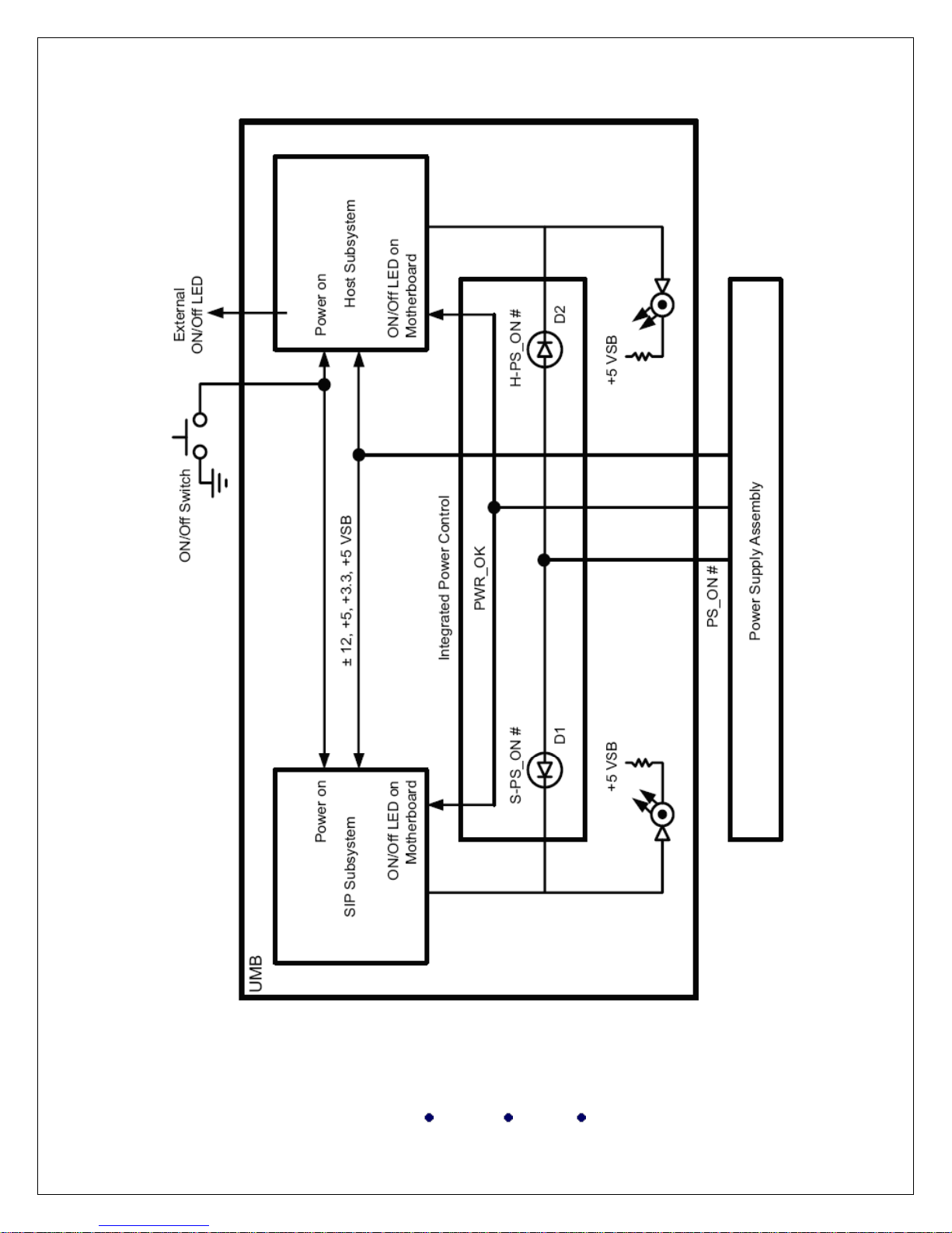
Power Theory (D.0 Systems)
Power enters the iE33 system via the AC receptacle, located on the
AC Tray. Power is routed through the circuit breaker, is filtered, and is sent
to the +12 VSB power supply. When the +12 VSB is within regulation, the
system awaits a signal from the operator to start system operation.
Pressing the On/Off switch activates a timer that holds the AC relay
closed for about 4 seconds.
Pressing the On/Off switch initiates a PS-ON_n signal at the Unified
Motherboard (UMB). The PS_ON_n signal is routed to the Acquisition
Power Distribution Board (APDB) where it initiates the startup logic
sequence.
The APDB also supplies +5 VSB originating from the +12 VSB on
the Battery Thermal Management (BTM) board to the AC Tray to light the
blue LED. After internal sequencing, the UMB sends a PS_ON_n signal to
the Signal and Power Distribution board (SPD). The SPD sends inhibit
signals to allow the Acquisition and Platform Power Supplies (APS and
PPS) to power-up their DC outputs. The SPD also sends a signal to hold the
AC relay closed after the initial 4-second delay.
After the AC relay is energized, the APS and PPS are turned on by a
signal from the APDB. As each power supply comes up, window
comparators monitor the individual voltages (+48 V, ±15 V, ±5.35 V, and
+3.65 V). If the voltages are within range, each power supply develops a
DC_OK signal.
Ultrasound Sales Service Repair Training
1815 Industrial Drive, Suite 100 Stockton, CA 95206
Conquest Imaging
PH: 209-942-2654 FAX: 209-942-2572
Rev3 070208.dms

- 26 -
The two signals are combined (OR’d) and produce a single
DC_OK_OUT signal. The signal is sent to the UMB. When the UMB
receives the signal, it initializes and bootup begins. The DC_OK_OUT
signal is also used to set the next On/Off switch closure as a shutdown
command.
Once the system is operational, pressing the On/Off switch opens the
AC relay and removes power from the APS and PPS. While this is
occurring, the system continues to consume DC power, which ensures that
the charges on the power supplies diminish quickly according to
specifications.
Pressing the On/Off switch also activates a circuit on the SPD that
initiates a 20-second lockout of On/Off switch. This enables the system to
power up without interference from another switch depression (during the
power-up cycle, the user is not able to force a power-off state by pressing the
switch).
At system power-up, the Battery and Thermal Management (BTM)
board sets the Platform and Acquisition fan speeds at full speed. During
system operation, the BTM board continues to monitor the system
temperature and automatically adjust fan speed.
Ultrasound Sales Service Repair Training
1815 Industrial Drive, Suite 100 Stockton, CA 95206
Conquest Imaging
PH: 209-942-2654 FAX: 209-942-2572
Rev3 070208.dms
- 27 -
Ultrasound Sales Service Repair Training
1815 Industrial Drive, Suite 100 Stockton, CA 95206
Conquest Imaging
PH: 209-942-2654 FAX: 209-942-2572
Rev3 070208.dms

- 28 -
Battery Charging Theory (D.0 Systems)
For systems with D.0 hardware, the system batteries have been
disconnected and the battery charging circuits are not operational.
USB Port Power Theory (D.0 Systems)
The Universal Serial Bus (USB) ports on the back of the DVD drive
and on the UAVIO are powered by system power from the UMB. If system
power is on, the ports are powered. If the system is off, there is no power to
the USB ports.
Signal and Power Distribution Board (SPD) (D.0 Systems)
• Provides On/Off switch conditioning. Disables the switch for
approximately 20 seconds after first depression, unless power is removed
(Figure 4-3)
• Provides an interface between the UMB and the rest of the system.
Cables to the SPD are designed to enable the UMB to slide out of the
system for maintenance
• Contains a remote On/Off switch for FSE use during system
maintenance
• Receives LVDS signals from the UMB, re-clocks the signals, and sends
them to the UAVIO
• Generates the platform power good signal (PLT_POWER_GOOD)
when all power supplies on the board are within regulation
• Provides a +5.01 V reference voltage to voltage comparators on the
SPD
• Regulates the +5 Vdc and +3.3 Vdc
• Uses the +5 Vdc and +3.3 Vdc to monitor the +12 Vdc.
• Provides overvoltage shutdown protection for the +5 Vdc and +3.3 Vdc
regulators. Latches the regulators off if the voltage is out of spec
• Provides -12 Vdc to track the +12 Vdc
Ultrasound Sales Service Repair Training
1815 Industrial Drive, Suite 100 Stockton, CA 95206
Conquest Imaging
PH: 209-942-2654 FAX: 209-942-2572
Rev3 070208.dms

- 29 -
Battery Thermal Management (BTM) (D.0 Systems Only)
Provides Platform Card Cage and Acquisition Card Cage fan tachometer
readings to system software for fault isolation purposes. Tachometer
readings are used only for fault isolation. (They are not used for speed
control.)
• Sets platform and acquisition fans at full speed during system power-up
• Provides an I2C bus interface to send BTM board identification data to
the rest of the system
AC Tray (D.0 Systems)
• Displays power status with a blue LED on the rear of the tray.
• Controls AC power to the Acquisition and Platform Power Supplies by
using a board-mounted AC relay. The relay is energized by logic on the
Acquisition Power Distribution Board. The relay controls AC power to
the Acquisition Power Supply, the Platform Power Supply, and OEM
input power.
• Configures winding of OEM AC transformer for 90- to 127-Vac, or
220-Vac input power (via two connectors). The AC Trays are sent
correctly configured from the factory.
• Provides EMI filtering on AC power lines.
• Generates and routes +12 VSB (standby power) to the Signal and
Power Distribution Board (SPD).
• Provides ground lugs for input power and customer equipment
connections.
• Receives +5 VSB to light the LED from the Acquisition Power
Distribution Board.
HV Switcher (D.0 Systems Only)
• Converts ±15 Vdc and +48 Vdc from the Acquisition Power Supply to
±HV (±30 to ±120 Vdc)
• Supplies ±HV to the NAIM HV regulators for low-pass filtering to
reduce power supply noise and to the Channel Boards through the
Acquisition Frontplane (for all transmit waveforms except CW)
• During CW, turns off power converters supplying ±HV bus and
switches the ±15 Vdc to the ±HV bus
Ultrasound Sales Service Repair Training
1815 Industrial Drive, Suite 100 Stockton, CA 95206
Conquest Imaging
PH: 209-942-2654 FAX: 209-942-2572
Rev3 070208.dms

- 30 -
• Routes HV to the transducer connector, to provide power for HV MUX
devices in the transducer and to power pulsers of the matrix array.
Ultrasound Sales Service Repair Training
1815 Industrial Drive, Suite 100 Stockton, CA 95206
Conquest Imaging
PH: 209-942-2654 FAX: 209-942-2572
Rev3 070208.dms

- 31 -
Power Subsystems (E.0)
The E.0 power subsystem contains:
• Power Supply Assembly
- Platform Power Supply (PPS)
- Power System and Battery Controller (PSBC) Board
- Acquisition Power Supply (APS)
• Signal and Power Distribution Board (SPD)
• AC Tray
Power Theory (E.0 Systems)
Power enters the iE33 system via the AC receptacle, located on the
AC Tray. Power is routed through the circuit breaker, is filtered, and is sent
to the +12 VSB power supply. When the +12 VSB is within regulation, the
system awaits a signal from the operator to start system operation. Pressing
the On/Off switch activates a timer that holds the AC relay closed for about
4 seconds.
Once the Acquisition and Platform Power Supplies have charged their
internal high voltage bus, each send an AC_OK signal to the Power System
and Battery Controller (PSBC). The PSBC then sends a pulsed signal to the
UMB. (This pulsed signal replaces the momentary low-pulse signal sent
directly to the mother board from the On/Off switch).
After internal sequencing, the UMB motherboard sends a PS_ON_n
signal to the PSBC. The PSBC sends inhibit signals to allow the Acquisition
and Platform power supplies to power up their DC outputs. The PSBC also
sends a signal to hold the AC relay closed after the initial 4-second delay.
The power supplies then bring all buses up to the proper specifications
and send the DC_OK_OUT signal to the UMB. When the UMB receives
this signal, it initializes and bootup begins. The DC_OK_OUT signal is also
used to set the next On/Off switch closure as a shutdown command.
When the system starts from a standby state, AC power is applied to
the standby power supply in the AC Tray, however, the AC relay has
opened, removing power from the PPS and APS. This places the system in
the initial power-up sequence at the point when the +12 VSB powers up.
Ultrasound Sales Service Repair Training
1815 Industrial Drive, Suite 100 Stockton, CA 95206
Conquest Imaging
PH: 209-942-2654 FAX: 209-942-2572
Rev3 070208.dms
 Loading...