


 Loading...
INSTRUCTIONS FOR USE
IntelliVue Patient Monitor
MP5
Release G.0 with Software Revision G.0x.xx
Patient Monitoring

Part Number M8105-9001C Printed in Germany 09/08 4512 610 29031
*M8105-9001C*

M8105-9001C
|
Table Of Contents |
|
|
1 Installation |
1 |
|
|
|
Installation Checklist |
1 |
|
Unpacking and Checking the Shipment |
2 |
|
Mounting the Monitor |
3 |
|
Connecting the Monitor to AC Mains |
3 |
|
Checking Out The Monitor |
3 |
|
Loading Paper |
4 |
|
Operating the Monitor |
5 |
|
Setting the Date and Time |
6 |
|
Checking Country-Specific Default Settings |
6 |
|
Handing Over the Monitor |
6 |
|
|
2 Basic Operation |
9 |
|
|
|
Introducing the Monitor |
9 |
|
Operating and Navigating |
13 |
|
Operating Modes |
19 |
|
Understanding Screens |
20 |
|
Using the XDS Remote Display (not MP5T) |
21 |
|
Using the Visitor Screen |
21 |
|
Understanding Profiles |
22 |
|
Understanding Settings |
24 |
|
Adjusting a Measurement Wave |
25 |
|
Freezing Waves |
26 |
|
Using Labels |
27 |
|
Entering Measurements Manually |
29 |
|
Changing Monitor Settings |
29 |
|
Checking Your Monitor Revision |
30 |
|
Getting Started |
30 |
|
Disconnecting from Power |
32 |
|
Networked Monitoring |
32 |
|
Using the MP5 with a Host Monitor |
33 |
|
|
3 What’s New? |
35 |
|
|
|
What’s New in Release G.0? |
35 |
|
What’s New in Release F.0? |
36 |
|
|
4 Alarms |
39 |
|
|
|
Visual Alarm Indicators |
40 |
|
Audible Alarm Indicators |
41 |
|
Acknowledging Alarms |
43 |
|
Pausing or Switching Off Alarms |
44 |
|
Alarm Limits |
45 |
|
Reviewing Alarms |
50 |
|
i

Latching Alarms |
52 |
||
Testing Alarms |
52 |
||
Alarm Behavior at On/Off |
53 |
||
Alarm Recordings |
53 |
||
|
5 Patient Alarms and INOPs |
55 |
|
|
|
|
|
Patient Alarm Messages |
55 |
||
Technical Alarm Messages (INOPs) |
61 |
||
|
6 Managing Patients |
85 |
|
|
|
|
|
Admitting a Patient |
85 |
||
Quick Admitting a Patient |
87 |
||
Editing Patient Information |
87 |
||
Discharging a Patient |
88 |
||
Transferring Patients |
89 |
||
Care Groups |
92 |
||
|
7 ECG, Arrhythmia, ST and QT Monitoring |
99 |
|
|
|
|
|
Skin Preparation for Electrode Placement |
99 |
||
Connecting ECG Cables |
99 |
||
Selecting the Primary and Secondary ECG Leads |
100 |
||
Checking Paced Status |
100 |
||
Understanding the ECG Display |
100 |
||
Monitoring Paced Patients |
101 |
||
Changing the Size of the ECG Wave |
103 |
||
Changing the Volume of the QRS Tone |
103 |
||
Changing the ECG Filter Settings |
104 |
||
Selecting Positions of Va and Vb Chest Leads (for 6-lead placement) |
104 |
||
Choosing EASI or Standard Lead Placement |
105 |
||
About ECG Leads |
105 |
||
ECG Lead Fallback |
106 |
||
ECG Lead Placements |
106 |
||
Capture 12-Lead |
110 |
||
EASI ECG Lead Placement |
111 |
||
ECG and Arrhythmia Alarm Overview |
112 |
||
Using ECG Alarms |
113 |
||
ECG Safety Information |
114 |
||
About Arrhythmia Monitoring |
115 |
||
Switching Arrhythmia Analysis On and Off |
116 |
||
Choosing an ECG Lead for Arrhythmia Monitoring |
116 |
||
Understanding the Arrhythmia Display |
117 |
||
Arrhythmia Relearning |
120 |
||
Arrhythmia Alarms |
121 |
||
About ST Monitoring |
127 |
||
Switching ST On and Off |
127 |
||
Understanding the ST Display |
128 |
||
ii

Updating ST Baseline Snippets |
129 |
||
Recording ST Segments |
130 |
||
About the ST Measurement Points |
130 |
||
ST Alarms |
132 |
||
Viewing ST Maps |
133 |
||
About QT/QTc Interval Monitoring |
137 |
||
QT Alarms |
140 |
||
Switching QT Monitoring On and Off |
141 |
||
|
8 Monitoring Pulse Rate |
143 |
|
|
|
|
|
Entering the Setup Pulse Menu |
143 |
||
System Pulse Source |
143 |
||
Switching Pulse On and Off |
144 |
||
Using Pulse Alarms |
144 |
||
|
9 Monitoring Respiration Rate (Resp) |
147 |
|
|
|
|
|
Lead Placement for Monitoring Resp |
147 |
||
Understanding the Resp Display |
148 |
||
Changing Resp Detection Modes |
148 |
||
Changing the Size of the Respiration Wave |
149 |
||
Changing the Speed of the Respiration Wave |
150 |
||
Using Resp Alarms |
150 |
||
Changing the Apnea Alarm Delay |
150 |
||
Resp Safety Information |
150 |
||
10 Monitoring SpO2 |
153 |
||
|
|
|
|
SpO2 Sensors |
153 |
||
Applying the Sensor |
153 |
||
Connecting SpO2 Cables |
154 |
||
Measuring SpO2 |
154 |
||
SpO2 Signal Quality Indicator (Fast SpO2 only) |
155 |
||
Assessing a Suspicious SpO2 Reading |
155 |
||
Changing the Averaging Time |
156 |
||
Setting the Measurement Mode |
156 |
||
Understanding SpO2 Alarms |
156 |
||
Pleth Wave |
157 |
||
Perfusion Numeric |
158 |
||
Perfusion Change Indicator |
158 |
||
Setting SpO2/Pleth as Pulse Source |
158 |
||
Setting Up Tone Modulation |
158 |
||
Setting the QRS Volume |
159 |
||
11 Monitoring NBP |
161 |
||
|
|
|
|
Introducing the Oscillometric NBP Measurement |
161 |
||
Preparing to Measure NBP |
162 |
||
Starting and Stopping Measurements |
164 |
||
iii

Enabling Automatic Mode and Setting Repetition Time |
165 |
||
Enabling Sequence Mode and Setting Up The Sequence |
165 |
||
Choosing the NBP Alarm Source |
166 |
||
Switching Pulse from NBP On/Off |
166 |
||
Assisting Venous Puncture |
167 |
||
Calibrating NBP |
167 |
||
12 Measuring Predictive Temperature |
169 |
||
|
|
|
|
Making a Temperature Measurement |
169 |
||
13 Monitoring Temperature |
173 |
||
|
|
|
|
Making a Temp Measurement |
173 |
||
Calculating Temp Difference |
174 |
||
14 Monitoring Invasive Pressure |
175 |
||
|
|
|
|
Setting up the Pressure Measurement |
175 |
||
Zeroing the Pressure Transducer |
176 |
||
Adjusting the Calibration Factor |
178 |
||
Displaying a Mean Pressure Value Only |
178 |
||
Changing the Pressure Wave Scale |
178 |
||
Optimizing the Waveform |
179 |
||
Using the Wave Cursor |
179 |
||
Non-Physiological Artifact Suppression |
179 |
||
Choosing the Pressure Alarm Source |
179 |
||
Calibrating Reusable Transducer CPJ840J6 |
181 |
||
Calculating Cerebral Perfusion |
182 |
||
Calculating Pulse Pressure Variation |
182 |
||
15 Monitoring Carbon Dioxide |
185 |
||
|
|
|
|
Using the CO2 Measurement |
186 |
||
Measuring Microstream CO2 |
189 |
||
Setting up all CO2 Measurements |
190 |
||
16 Assigning Two Devices to One Patient |
195 |
||
|
|
|
|
How Can You Combine Devices? |
195 |
||
Functions Available When the Telemetry Data Window is Displayed |
199 |
||
Functions Available For Devices Connected Via SRR |
200 |
||
General Telemetry-related Functions |
201 |
||
Use Models With Telemetry |
202 |
||
17 Enhancing Telemetry Monitoring with the Monitor |
205 |
||
|
|
|
|
18 Trends |
207 |
||
|
|
|
|
Viewing Trends |
207 |
||
Setting Up Trends |
210 |
||
Documenting Trends |
213 |
||
iv

Trends Databases |
214 |
||
Screen Trends |
215 |
||
19 High Resolution Trend Waves |
219 |
||
|
|
|
|
OxyCRG |
219 |
||
Printing Hi-Res Trend Wave Reports |
219 |
||
Hi-Res Trend Wave Recordings |
220 |
||
20 Event Surveillance |
221 |
||
|
|
|
|
Event Episodes |
221 |
||
Events Pop-Up Keys |
222 |
||
Event Triggers |
222 |
||
The Events Database |
224 |
||
Viewing Events |
224 |
||
Annotating Events |
226 |
||
Documenting Events |
226 |
||
21 ProtocolWatch |
231 |
||
|
|
|
|
Severe Sepsis Screening |
231 |
||
22 Recording |
237 |
||
|
|
|
|
Starting and Stopping Recordings |
237 |
||
Overview of Recording Types |
238 |
||
All ECG Waves Recordings |
239 |
||
Creating and Changing Recordings Templates |
239 |
||
Changing ECG Wave Gain |
240 |
||
Recording Priorities |
241 |
||
Sample Recording Strip |
241 |
||
Reloading Paper |
243 |
||
Recorder Status Messages |
243 |
||
23 Printing Patient Reports |
245 |
||
|
|
|
|
Starting Report Printouts |
245 |
||
Stopping Reports Printouts |
246 |
||
Setting Up Reports |
246 |
||
Setting Up Individual Print Jobs |
248 |
||
Checking Printer Settings |
249 |
||
Printing a Test Report |
249 |
||
Switching Printers On Or Off for Reports |
249 |
||
Dashed Lines on Reports |
249 |
||
Unavailable Printer: Re-routing Reports |
249 |
||
Checking Report Status and Printing Manually |
250 |
||
Printer Status Messages |
251 |
||
Sample Report Printouts |
252 |
||
v

24 Using the Drug Calculator |
257 |
||
|
|
|
|
Accessing the Drug Calculator |
257 |
||
Performing Drug Calculations |
258 |
||
Charting Infusion Progress |
260 |
||
Using the Titration Table |
260 |
||
Documenting Drug Calculations |
260 |
||
25 Using the Timer |
261 |
||
|
|
|
|
Viewing the Timer |
261 |
||
Timer Setup Pop-up Keys |
261 |
||
Setting Up Timers |
262 |
||
Displaying a Timer On The Main Screen |
263 |
||
Displaying A Clock On The Main Screen |
264 |
||
26 Laboratory Data |
265 |
||
|
|
|
|
Viewing Received Data |
265 |
||
27 Care and Cleaning |
267 |
||
|
|
|
|
General Points |
267 |
||
Cleaning the Monitor |
268 |
||
Disinfecting the Monitor |
268 |
||
Sterilizing the Monitor |
268 |
||
Cleaning, Sterilizing and Disinfecting Monitoring Accessories |
269 |
||
Cleaning and Disinfecting the Predictive Temperature Accessories |
269 |
||
Cleaning Batteries and the Battery Compartment |
269 |
||
28 Using Batteries |
271 |
||
|
|
|
|
Battery Power Indicators |
271 |
||
Checking Battery Charge |
274 |
||
Replacing a Battery |
274 |
||
Optimizing Battery Performance |
274 |
||
Battery Safety Information |
275 |
||
29 Maintenance and Troubleshooting |
277 |
||
|
|
|
|
Inspecting the Equipment and Accessories |
277 |
||
Inspecting the Cables and Cords |
277 |
||
Maintenance Task and Test Schedule |
278 |
||
Troubleshooting |
279 |
||
Disposing of the Monitor |
279 |
||
Disposing of Empty Calibration Gas Cylinders |
279 |
||
30 Accessories |
281 |
||
|
|
|
|
ECG/Resp Accessories |
281 |
||
NBP Accessories |
285 |
||
Invasive Pressure Accessories |
286 |
||
SpO2 Accessories |
287 |
||
vi

Temperature Accessories |
291 |
||
Predictive Temperature Accessories |
291 |
||
Mainstream CO2 Accessories |
292 |
||
Sidestream CO2 Accessories |
292 |
||
Microstream CO2 Accessories |
292 |
||
Recorder Accessories |
293 |
||
Cable for Direct Connection of a Telemetry Device |
294 |
||
Battery Accessories |
294 |
||
31 Installation and Specifications |
295 |
||
|
|
|
|
Intended Use |
295 |
||
Manufacturer’s Information |
296 |
||
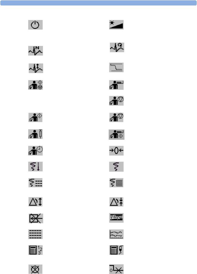
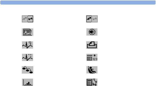
Symbols |
296 |
||
Installation Safety Information |
298 |
||
Altitude Setting |
300 |
||
Monitor Safety Specifications |
300 |
||
EMC And Radio Regulatory Compliance |
301 |
||
Out-Of-Hospital Transport - Standards Compliance |
302 |
||
Monitor Performance Specifications |
304 |
||
M4605A Battery Specifications |
308 |
||
Measurement Specifications |
309 |
||
Safety and Performance Tests |
321 |
||
32 Default Settings Appendix |
327 |
||
|
|
|
|
Country-Specific Default Settings |
327 |
||
Alarm and Measurement Default Settings |
333 |
||
Alarm Default Settings |
333 |
||
ECG, Arrhythmia, ST and QT Default Settings |
334 |
||
Pulse Default Settings |
337 |
||
Respiration Default Settings |
337 |
||
SpO2 Default Settings |
338 |
||
NBP Default Settings |
339 |
||
Temperature Default Settings |
339 |
||
Predictive Temperature Default Settings |
340 |
||
Invasive Pressure Default Settings |
340 |
||
CO2 Default Settings |
342 |
||
vii

viii
1
Installation
Installation should be carried out by qualified service personnel, either by the hospital’s biomedical department, or by Philips Support.
If you have purchased a “customer-installable bundle”, it is assumed that your own hospital personnel will install and, if necessary, configure the monitor. You can contact Philips Support for assistance if required; any assistance will be associated with additional costs.
For mechanical and electrical installation, you need technically qualified personnel with a knowledge of english. Additionally, for monitor configuration, you need clinically qualified personnel with a knowledge of the use environment. For further information on Installation, refer to the Service Guide.
WARNING • Monitor configuration settings must be specified by authorized hospital personnel.
•For installation of the monitor as part of a system, always refer to the Service Guide.
•As the first step in preparing the monitor for use, follow the installation instructions given in this chapter.
Installation Checklist
Use this checklist to document your installation.
Step |
Task |
Check Box |
|
|
when Task |
|
|
Done |
|
|
|
1 |
Perform initial inspection of delivery, unpack and check the shipment (see |
|
|
“Unpacking and Checking the Shipment” on page 2) |
|
2 |
Mount the monitor as appropriate for your installation (see “Mounting the |
|
|
Monitor” on page 3) |
|
3 |
Connect the monitor to AC mains using the supplied power cord (see |
|
|
“Connecting the Monitor to AC Mains” on page 3) |
|
4 |
Perform Visual, Power On and Functional test blocks (see “Checking Out |
|
|
The Monitor” on page 3) |
|
5 |
Perform Safety Tests, if required by local laws and regulations (see “Checking |
|
|
Out The Monitor” on page 3) |
|
6 |
Load paper into the recorder, if present (see “Loading Paper” on page 4) |
|
|
|
|
1

1 Installation |
Unpacking and Checking the Shipment |
Step |
Task |
Check Box |
|
|
when Task |
|
|
Done |
|
|
|
7 |
Check/set the time and date (see “Setting the Date and Time” on page 6) |
|
8 |
Check that the country-specific default settings are appropriate (see |
|
|
“Checking Country-Specific Default Settings” on page 6) |
|
9 |
Perform System Test as necessary (see the Service Guide) |
|
|
|
|
Unpacking and Checking the Shipment
The monitor and any supporting options ordered are supplied packed in protective shipping cartons.
Initial Inspection
Before unpacking, check the packaging and ensure that there are no signs of mishandling or damage. Open the package carefully and remove the monitor and accessories.
Check that the contents are complete and that the correct options and accessories have been delivered.
System Components, Accessories and Supplies |
Comments |
|
|
Monitor with options as ordered |
1 |
ECG accessories |
optional |
NBP accessories |
1 |
SpO2 accessories |
optional |
Pressure accessories |
optional |
Temperature accessories |
optional |
Predictive Temperature accessories |
optional |
CO2 Accessories |
optional |
Recorder paper |
optional |
Powercord |
1 |
Telemetry Interface cable |
optional |
Measurement Link (MSL) cable |
optional |
Instructions for Use |
1 |
Quick Guide |
1 |
Documentation CD-ROM (includes Service Guide and Instructions |
1 |
for Use) |
|
|
|
Claims for Damage
If the shipping cartons are damaged, contact the carrier.
If any of the equipment is damaged, contact both the carrier and your local Philips service organization for repair or replacement arrangements.
2

Mounting the Monitor |
1 Installation |
Repacking
Retain the original packing carton and material, in case you need to return equipment to Philips for service. If you no longer have the original packing materials, Philips can advise you on alternatives.
Mounting the Monitor
The monitor can be rested on a flat surface, hung on the bed rail, or mounted on a wall. See the Service Guide for details.
Connecting the Monitor to AC Mains
The monitor has a wide-range power supply that allows you to operate the monitor from an AC (alternating current) power source of 100 V to 240 V (± 10%) and 50 to 60 Hz (± 5%).
WARNING • Always use the supplied power cord with the earthed mains plug to connect the monitor to an earthed AC mains socket. Never adapt the mains plug from the power supply to fit an unearthed AC mains socket.
•Do not use AC mains extension cords or multiple portable socket-outlets. If a multiple portable socket-outlet without an approved isolation transformer is used, the interruption of its protective earthing may result in enclosure leakage currents equal to the sum of the individual earth leakage currents, so exceeding allowable limits.
•Do not connect any devices that are not supported as part of a system.
•Any non-medical device placed and operated in the patient’s vicinity must be powered via an approved isolation transformer that ensures mechanical fixing of the power cords and covering of any unused power outlets.
Checking Out The Monitor
The following table defines which tests and inspections need to be performed, and when they are required.
Test |
Test or Inspection to be Performed |
|
|
Visual |
Inspect the monitor, measurement accessories and cables for any damage. |
|
Are they free of damage? |
Power On |
Power on the monitor. Does it start up successfully without errors? Do all alarm |
|
lamps light up during power up? |
|
After start up the monitor sounds a tone, and you can see the monitoring main |
|
screen (normally with measurement wave channels and numeric positions). |
Functionality Test |
After power up, touch the blue Main Screen key at the bottom right of the |
|
screen to test the Touchscreen. The key should turn light blue then after several |
|
seconds return to its standard blue color. |
|
|
3

1 Installation |
Loading Paper |
Test |
Test or Inspection to be Performed |
|
|
Safety Tests (1) to (4) |
Perform safety tests (1) to (4), as described in the Service Guide, for standalone |
|
devices if required by local laws and regulations, and each time you combine |
|
equipment to form a system, or exchange system components. Details of the |
|
safety tests and procedures are described in the Service Guide. These safety |
|
tests are derived from international standards but may not always be |
|
sufficient to meet local requirements. |
System |
Perform the system test according to IEC 60601-1-1, if applicable, after |
|
combining equipment to form a system (see the Service Guide). |
|
|
For test and inspection information regarding repairs, upgrades and all other service events, refer to the
Service Guide.
Loading Paper
1Use the latch on the right side of the recorder door to pull the door open.
2Remove the empty core.
3Insert a new roll and secure it in place on the paper holder. The paper feeds from the bottom of the roll and over the top of the recorder door. Recommended paper: M4816A and M4817A.
4With at least one inch of paper extending beyond the edge of the door, swing the recorder door up and push it firmly closed.
5To test if paper is loaded correctly, start a recording. If no printing appears, paper may be loaded backwards. Try reloading the paper.
4
Operating the Monitor |
1 Installation |
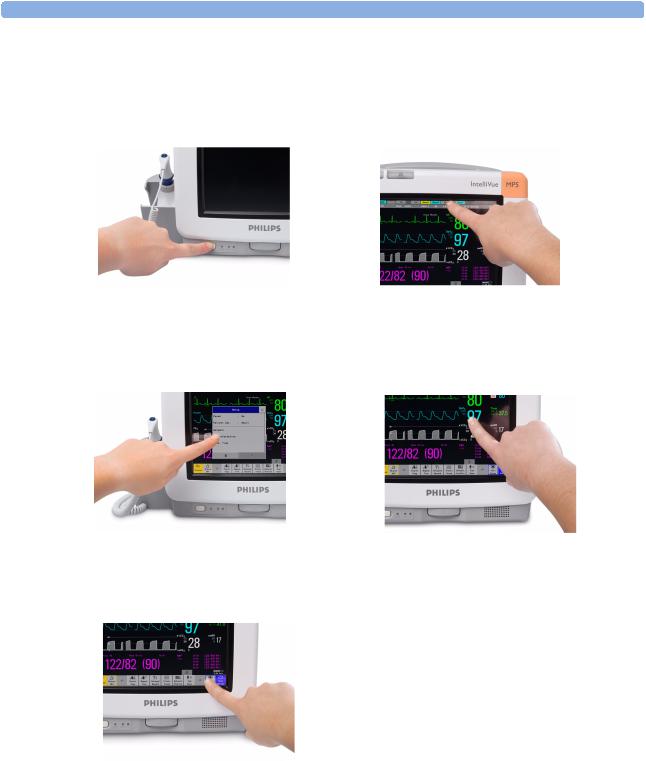
Operating the Monitor
To complete installation you will need to operate the monitor. Here is a short introduction for those not experienced with IntelliVue monitors.
1 Switch on the monitor. After start-up the monitor display will become active. You operate the monitor using the touch screen.
2Touch something on the screen to enter a menu. Touching the time, as shown here, brings you to the date and time menu needed for the next section.
3 Touch again to select an item on the menu and 4 |
You can touch numerics, waves and any |
||
|
work through the menu activities. |
item on the screen, to get you to the |
|
|
|
|
corresponding menu. |
|
|
|
|
|
|
|
|
5If you cannot find a menu by touching the screen you can always use the Main Setup key which will get you to all menus on the monitor
5

1 Installation |
Setting the Date and Time |
Setting the Date and Time
To set the date and time:
1Select the Date, Time screen element from the monitor’s info line to enter the Date, Time menu.
2Select, in turn, the Year, Month, Day, Hour (in 24 hour format, only) and Minute as necessary. Select the correct values from the pop-up list.
3Select Store Date, Time to change the date and time.
If your monitor is connected to an Information Center, the date and time are automatically taken from this.
Once it is set, the internal clock retains the setting even when you switch off the monitor.
Checking Country-Specific Default Settings
Some settings are made in the factory to match the typical requirements in a specific country. Line frequency, units for weight and height, and ECG cable colors (AAMI or IEC) have been set to appropriate values. If you suspect that these settings may not match your institution’s requirements, check the settings and change them if necessary as described in the Configuration Guide.
WARNING Before starting monitoring, check that the current configuration meets your requirements, especially patient category, alarm limits and paced setting.
If you need to enter configuration mode:
1 In the Main Setup menu, select Operating Modes.
2Select Config and enter the passcode.
The passcode for configuration mode is given in the monitor’s service documentation.
The monitor displays Config at the right hand side of the status line and in the center of the Screen while you are in configuration mode.
Before you leave configuration mode, always be sure to store any changes you made. You must store changes made to each Settings Block and to each Profile, individually. As it may be difficult to remember whether the settings you changed belong to a Monitor Settings block or a Measurement Settings block, we recommend that you store each block before you leave configuration mode.
To leave configuration mode:
♦In the Main Setup menu, select Operating Modes and then select Monitoring.
Handing Over the Monitor
If you are handing over the monitor to the end-users directly after configuration, make sure that it is in Monitoring mode.
Ensure that the users have access to the following documentation delivered with the monitor:
•Instructions for Use (this book) - for more detailed questions during use
•Quick Guide - for quick reminders during use
6

Handing Over the Monitor |
1 Installation |
Additionally, we recommend working through the Training Guide for self-training on the monitor before use (not available in all languages). The part number is M8105-944XB, where X is a digit dependent on the language. The English training guide is M8105-9441B. An English training video, M8000-9451E, is also available.
7

1 Installation |
Handing Over the Monitor |
8

2
Basic Operation
These Instructions for Use are for clinical professionals using the IntelliVue MP5 and MP5T (M8105A and M8105AT) patient monitors.
This basic operation section gives you an overview of the monitor and its functions. It tells you how to perform tasks that are common to all measurements (such as entering data, switching a measurement on and off, setting up and adjusting wave speeds, working with profiles). The alarms section gives an overview of alarms. The remaining sections tell you how to perform individual measurements, and how to care for and maintain the equipment.
Familiarize yourself with all instructions including warnings and cautions before starting to monitor patients. Read and keep the Instructions for Use that come with any accessories, as these contain important information about care and cleaning that is not repeated here.
This guide describes all features and options. Your monitor may not have all of them; they are not all available in all geographies. Your monitor is highly configurable. What you see on the screen, how the menus appear and so forth, depends on the way it has been tailored for your hospital and may not be exactly as shown here. In particular for the MP5T, refer to the table on the following page to see which sections of this guide are applicable to your monitor.
In this guide:
•A warning alerts you to a potential serious outcome, adverse event or safety hazard. Failure to observe a warning may result in death or serious injury to the user or patient.
•A caution alerts you to where special care is necessary for the safe and effective use of the product. Failure to observe a caution may result in minor or moderate personal injury or damage to the product or other property, and possibly in a remote risk of more serious injury.
•Monitor refers to the entire patient monitor. Display refers to the physical display unit. Display Screen and Screen refer to everything you see on monitor’s display, such as measurements, alarms, patient data and so forth.
Introducing the Monitor
The MP5 monitor provides a comprehensive set of basic physiological measurements: NBP, SpO2, and optionally ECG, invasive blood pressure, predictive temperature, standard temperature and CO2. Through networking it provides information integration, documentation and information access. The MP5 can be used with adult, pediatric and neonatal patients in a hospital and transport environment.
9

2 Basic Operation |
Introducing the Monitor |
The monitor stores data in trend and event databases. You can see tabular trends (vital signs) and document them on a central printer. You can view measurement trend graphs, with up to three measurements combined in each graph, to help you identify changes in the patient’s physiological condition. You can view fast-changing measurement trends with beat to beat resolution and see up to four high resolution trend segments.
The MP5 monitor can also be connected to another IntelliVue patient monitor (MP20 to MP90), where it acts as a multi-measurement module (MMS), acquiring measurements for the host monitor. When connected to a host monitor, the host controls the MP5 including all alarm functionality. No alarms are available on the MP5, and the alarm lamps are controlled by the host. You can recognize when an MP5 is connected to a host monitor by the following indication on the screen:
Companion Mode |
No Alarm Display |
When the MP5 is disconnected from the original host monitor, it continues to monitor the patient as a stand-alone monitor with all settings and data. On connection to a new host monitor, the MP5 resumes its role as MMS, transferring all settings and data, ensuring fully continuous monitoring. When the MP5 is connected to a host monitor it still requires batteries or AC power; it also cannot charge its batteries via the host monitor’s AC connection.
The MP5T monitor is intended for use together with a telemetry device. It has no ECG measurement of its own but does have NBP and optionally SpO2 and predictive temperature. When the telemetry device is directly connected to the MP5T, the measurements from the MP5T are transmitted with those from the telemetry device (ECG and optionally SpO2) to the Information Center. The MP5T alone has no network capability (no direct wired or wireless connection to the Information Center).
The following comparison table shows in detail the differences between MP5 and MP5T:
Functionality (including optional features) |
MP5 |
MP5T |
|
|
|
ECG |
3 |
|
|
|
|
SpO2 |
3 |
3 |
NBP |
3 |
3 |
|
|
|
Predictive Temperature |
3 |
3 |
|
|
|
Temperature |
3 |
|
|
|
|
Invasive Pressure |
3 |
|
|
|
|
Carbon Dioxide |
3 |
|
|
|
|
Direct Telemetry Connection |
3 |
3 |
|
|
|
ECG Output signal |
31 |
|
LAN networking capability |
3 |
|
|
|
|
WLAN networking capability |
3 |
|
|
|
|
Short range radio interface |
3 |
|
|
|
|
IntelliVue Instrument Telemetry networking capability |
3 |
|
|
|
|
Severe Sepsis Screening |
3 |
|
|
|
|
OxyCRG high resolution trend |
3 |
|
|
|
|
Neonatal event review |
3 |
|
|
|
|
Integrated recorder |
3 |
3 |
|
|
|
Drug Calculator |
3 |
3 |
|
|
|
10
Introducing the Monitor |
2 Basic Operation |
Functionality (including optional features) |
MP5 |
MP5T |
|
|
|
Gas monitor support |
3 |
|
|
|
|
Connection to a host monitor (companion mode) |
3 |
|
|
|
|
Connection to an external display |
3 |
|
|
|
|
Nurse call capability |
3 |
|
|
|
|
1.MP5 options without ECG do not have an ECG output signal
The MP5/MP5T patient monitor has an 8.4-inch TFT LCD flat panel SVGA display. You operate the monitor with the Touchscreen. There is an optional built-in recorder.
11
2 Basic Operation |
Introducing the Monitor |
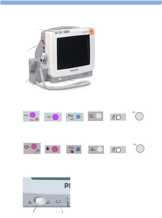
MP5/MP5T Major Parts and Keys
|
1 |
2 |
|
1 |
Color-coded alarm lamps |
|
|
|
2 |
Alarms off lamp |
|||
|
|
|
|
|||
|
|
|
|
3 |
Measurement connectors (see |
|
|
|
|
|
|
below) |
|
|
|
|
|
4 |
Predictive Temperature Unit |
|
3 |
|
|
|
5 |
ECG out (not MP5T and MP5 |
|
|
|
|
|
options without ECG) |
||
|
|
|
|
|
||
|
|
|
|
6 |
On/Standby Switch |
|
|
|
|
|
7 |
Indicator LEDs |
|
|
|
|
|
7 |
|
|
4 |
5 |
|
6 |
|
|
|
|
|
|
|
|
|
|
US measurement connectors |
|
|
|
|
||
Pressure |
Noninvasive |
SpO2 |
ECG/ |
Telemetry |
CO2 |
|
and Temp |
Pressure |
|
Respiration |
device |
|
|
International measurement connectors
Pressure |
Noninvasive |
SpO2 |
ECG/ |
Telemetry |
and Temp |
Pressure |
|
Respiration |
device |
MP5(T) front panel
1On/Standby switch
2On/Standby/Error LED - green when monitor is switched on, red if there is a problem with the monitor
3Battery status LED - green, yellow or red, see Battery section for details
4AC power operation LED - green when the monitor is
connected to AC power (mains)
1 |
2 |
3 |
4 |
12

Operating and Navigating |
2 Basic Operation |
Operating and Navigating
Everything you need to operate the monitor is contained on its screen. Almost every element on the screen is interactive. Screen elements include measurement numerics, waveforms, screen keys, information fields, alarms fields and menus:
1 |
2 |
3 |
|
4 |
5 |
6 |
7 |
8 |
9 |
|
Bed 3 |
|
|
Adult |
|
|
3 Waves A |
|
|
|
|
|
|
|
|
|
|||
|
Doe, John |
|
|
|
|
||||
|
II |
|
|
|
|
|
HR |
ALARMS PAUSED 2:59 |
|
|
|
|
|
|
|
Pulse |
|
||
|
1mv |
|
|
|
|
|
|
Temp |
|
|
Pleth |
|
|
|
|
|
SpO2 |
|
|
|
|
Resp |
|
|
|
|
|
|
|
|
RR |
|
|
|
|
|
|
|
1Ohm |
|
|
|
|
|
|
|
|
|
|
|
|
NBP |
|
Auto 10 min |
|
|
NBP |
|
|
|
||||
|
|
Sys. |
|
|
|
|
|
|
|
mmHg |
|
|
|
|
|
|
Local Recorder out of paper |
|
|
|
|
|
hrs |
||||||
10 |
|
|
|
|
|
|
|
|
|
|
|
|
||
|
|
|
|
|
|
|
|
|
|
|
|
|
||
|
|
Silence |
Pause |
|
Start/ |
Repeat |
Delayed |
Vitals |
Default End Case |
Main |
Main |
|||
|
|
|
|
Alarms |
|
Stop |
Time |
Record |
Trend |
Profile |
Setup |
Screen |
||
|
|
17 |
16 |
15 |
|
|
|
|
14 |
|
13 |
12 |
11 |
|
|
|
|
|
|
|
|
|
|
|
|
||||
|
Monitor information line |
|
|
Other screen elements |
|
|
|
|
||||||
|
|
|
|
|
|
|
|
|
||||||
|
1 |
|
network connection indicator |
|
10 |
|
status line - shows information and messages prompting you for action |
|
||||||
|
|
|
(documented in Information |
|
|
|
|
|
|
|
|
|
||
|
|
|
Center Instructions for Use) |
|
|
|
|
|
|
|
|
|
||
|
2 |
|
bed label |
|
|
11 |
|
close all open menus and windows and return to main screen |
|
|
||||
|
3 |
|
patient identification |
|
|
12 |
|
enter Main Setup menu |
|
|
|
|||
|
4 |
|
patient category |
|
|
13 |
|
scroll right to display more SmartKeys |
|
|
||||
|
5 |
|
paced status |
|
|
14 |
|
SmartKeys - these change according to your monitor’s configuration |
|
|
||||
|
6 |
|
date and time |
|
|
15 |
|
scroll left to display more SmartKeys |
|
|
|
|||
|
7 |
|
current screen name/enter |
|
16 |
|
Pause Alarms - pauses alarm indicators. Pause duration depends on monitor |
|||||||
|
|
|
change screen menu |
|
|
|
|
configuration. If pause duration is infinite, this key is labeled Alarms Off. Select again |
||||||
|
|
|
|
|
|
|
|
|
to immediately re-enable alarm indicators. |
|
|
|||
13
2 Basic Operation |
Operating and Navigating |
Monitor information line |
Other screen elements |
|
|
8 adjust alarm volume/level |
17 Silence - acknowledges all active alarms by switching off audible alarm indicators and |
indicator |
lamps permanently or temporarily, if alarm reminder (ReAlarm) is configured on. |
9alarm status area - shows active alarm messages
Selecting Screen Elements
Touch a screen element to get to the actions linked to that element. For example, touch the Patient Identification element to call up the Patient Demographics window, or touch the HR numeric to call up the Setup ECG menu. Touch the ECG wave segment to call up the ECG lead menu.
Using the Setup Menu
Setup
Alarm Messages
Alarm Limits
Alarm Volume
My Care Group
Change Screen
Profiles
Admit/Dischrg
Paced No
Network
Bed Information
Date, Time
The elements at the top of the Screen are grouped together for ease of navigation. Touch any item at the top of the Screen to open the Setup menu; then touch the element you want.
Disabling Touchscreen Operation
♦To temporarily disable touchscreen operation of the monitor, press and hold the Main Screen permanent key. A padlock will appear on the Main Screen permanent key.
♦Press and hold the Main Screen permanent key again to re-enable the touchscreen operation.
Moving Windows
You can move windows and menus using the Touchscreen. To move a window
1Select the title of the window and keep your finger on the title.
2Move your finger on the Touchscreen to move the window.
3Take your finger off the screen to place the window in the final position.
Not all locations on the screen can be a target position, a window cannot overlap the monitor info line, the alarms and INOPs or the status line.
14
Operating and Navigating |
2 Basic Operation |
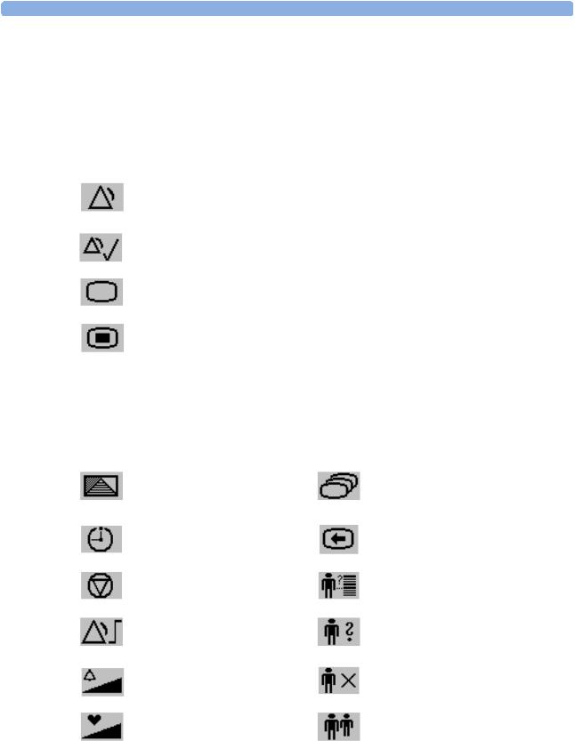
Using Keys
The monitor has three different types of keys.
Permanent Keys
A permanent key is a graphical key that remains on the screen all the time to give you fast access to functions.
Pause Alarms - pauses alarm indicators. Pause duration depends on monitor configuration. If pause duration is infinite, this key is labeled Alarms Off.
Select again to immediately re-enable alarm indicators.
Silence - acknowledges all active alarms by switching off audible alarm indicators and lamps.
Main Screen - close all open menus and windows and return to the main screen.
Main Setup - enter main setup menu.
SmartKeys
A SmartKey is a configurable graphical key, located at the bottom of the main screen. It gives you fast access to functions. The selection of SmartKeys available on your monitor depends on your monitor configuration and on the options purchased.
enter profile menu, or revert to default profile
access timers
freeze waves
set alarm limits
change alarm volume
change QRS volume
change Screen, or revert to default screen
previous Screen
quick admit a patient
enter patient identification menu to admit/discharge/transfer
end case to discharge a patient
view information for patients in other beds
15
2 Basic Operation
enter standby mode - suspends patient monitoring. All waves and numerics disappear from the display. All settings and patient data information are retained.
review beat labels (annotate arrhythmia wave)
change amplitude (size) of ECG wave
-start/stop manual NBP measurement
-start auto series
-stop current automatic measurement within series
start NBP measurement and measurement series
start veni puncture (inflate cuff to subdiastolic pressure)
set the NBP repeat time
start a delayed recording
access Vital Signs recording key
set wide automatic alarm limits
switch CO2 pump off
review vital signs trend
access the calculator
gas analyzer - exit standby mode
Operating and Navigating
change screen brightness (not for independent displays)
re-learn arrhythmia
access wedge procedure window
start/stop NBP STAT measurement
stop automatic or STAT NBP measurement and measurement series
stop current NBP measurement
start NBP STAT measurement
zero invasive pressure transducer
access pop-up recording keys
access Select Waves recording key
set narrow automatic alarm limits
access neonatal event review
review graph trend
access the Drug Calculator
suppress zero for all gas measurements
16
Operating and Navigating
unpair equipment and continue central monitoring with the monitor
start 12-Lead Capture (only available if Information Center is connected)
set standard or EASI lead placement
new lead setup
2 Basic Operation
unpair equipment and continue central monitoring with the telemetry device
access ST Map application
access patient reports
manual data entry
access ProtocolWatch |
start/stop car seat assessment record |
open the histogram window |
open unit conversion window |
Pop-Up Keys
Pop-up keys are task-related graphical keys that appear automatically on the monitor screen when required. For example, the confirm pop-up key appears only when you need to confirm a change.
Using the On-Screen Keyboard
Use this as you would a conventional keyboard. Enter the information by selecting one character after another. Use the Shift and capital Lock keys to access uppercase letters. Use the Back key to delete single characters, or use the Clr key to delete entire entries. Select Enter to confirm what you have entered and close the on-screen keyboard.
17

2 Basic Operation
Using the On-Screen Calculator
You can use the on-screen calculator to perform any of the standard operations for which you would normally use a handheld calculator.
♦To access the on-screen calculator, select the
Calculator SmartKey, or select Main Setup -> Calculations -> Calculator.
Operating and Navigating
Calculator
MC MR M+ Back
√C/CE
18

Operating Modes |
2 Basic Operation |
Operating Modes
When you switch the monitor on, it starts up in monitoring mode. To change to a different mode:
1Select the Main Setup menu.
2Select Operating Modes and choose the mode you require.
Your monitor has four operating modes. Some are passcode protected.
•Monitoring Mode: This is the normal, every day working mode that you use for monitoring patients. You can change elements such as alarm limits, patient category and so forth. When you discharge the patient, these elements return to their default values. Changes can be stored permanently only in Configuration Mode. You may see items, such as some menu options or the altitude setting, that are visible but ‘grayed out’ so that you can neither select nor change them. These are for your information and can be changed only in Configuration Mode.
•Demonstration Mode: Passcode protected, this is for demonstration purposes only. You must not change into Demonstration Mode during monitoring. In Demonstration Mode, all stored trend information is deleted from the monitor’s memory.
•Configuration Mode: Passcode protected, this mode is for personnel trained in configuration tasks. These tasks are described in the Configuration Guide. During installation the monitor is configured for use in your environment. This configuration defines the default settings you work with when you switch on, the number of waves you see and so forth.
•Service Mode: Passcode protected, this is for trained service personnel.
Config
When the monitor is in Demonstration Mode, Configuration Mode, or Service Mode, this is indicated by a box with the mode name in the center of the Screen and a symbol in the bottom right-hand corner. Select this field to change to a different mode.
When an MP5 is connected to a host monitor (Companion Mode is indicated):
•The MP5 will adopt the operating mode of the host monitor:
•You cannot change the operating mode at the MP5.
Standby Mode
Standby mode can be used when you want to temporarily interrupt monitoring.
To enter Standby mode,
♦select the Monitor Standby SmartKey or
♦select Main Setup, followed by Monitor Standby.
The monitor enters Standby mode automatically after the End Case function is used to discharge a patient.
Standby suspends patient monitoring. All waves and numerics disappear from the display but all settings and patient data information are retained. A special Standby screen is displayed. This can be configured to a moving image or a blank screen. If a patient location is entered at the Information Center, this will also be displayed on the Standby screen (availability depends on Information Center revision).
To resume monitoring,
19

2 Basic Operation |
Understanding Screens |
♦Select anything on the screen or press any key.
If you connect an MP5 that is powered on (and not in Standby) to a host monitor in Standby mode, the host will leave Standby mode. When connected to a host monitor, with both the host and the MP5 in Standby mode, leaving Standby on the MP5 will also make the host leave Standby.
Understanding Screens
Your monitor comes with a set of preconfigured Screens, optimized for common monitoring scenarios such as OR adult, or ICU neonatal. A Screen defines the overall selection, size and position of waves, numerics and SmartKeys on the monitor screen when you switch on. You can easily switch between different Screens during monitoring. Screens do NOT affect alarm settings, patient category and so forth.
Switching to a Different Screen
1To switch to a different Screen, select the monitor info line and then Change Screen in the Setup Menu, or select the Change Screen SmartKey.
2Choose the new Screen from the pop-up list.
Changing a Screen’s Content
If you do not want to change the entire Screen content, but only some parts of it, you can substitute individual waves, numerics, high-res waves, or trends. Be aware that these changes cannot be stored permanently in Monitoring Mode.
To change the selection of elements on a Screen,
1Select the element you want to change.
2From the menu that appears, select Change Wave, Change Numeric, or
Change HiResTrend, and then select the wave or numeric you want, or select the highresolution trend wave you want from the list of available waves.
If you do not see Change Numeric in the menu, this Screen may be configured to always display the numeric beside its wave. Changing the wave will automatically change the numeric.
The changed Screen is shown with an asterisk in the monitor info line.
20
Loading...