


Installation/Troubleshooting
Network Camera Outdoor Ready
Model No. BB-HCM371A
Please read this manual before using and save this manual for future reference. Panasonic Network Camera Website: http://www.panasonic.com/netcam
for customers in the USA or Puerto Rico

Installation/Troubleshooting
Introduction
How to Use This Documentation
The camera includes the following 2 manual types.
•Installation/Troubleshooting (This manual)
Installation/Troubleshooting provides explanations for accessories included with the camera, the initial configuration, and troubleshooting tips. The Installation/Troubleshooting helps you to easily configure the camera.
•Operating Instructions (Included on the Setup CD-ROM)
Operating Instructions explains about operations, settings, features and the cleaning method when using the camera.
Abbreviations
•UPnP is the abbreviation for Universal Plug and Play.
•"Network Camera" is called "Camera" in this Installation/Troubleshooting.
Trademarks
•Adobe, Acrobat and Reader are either registered trademarks or trademarks of Adobe Systems Incorporated in the United States and/or other countries.
•Ethernet is either a registered trademark or a trademark of Xerox Corporation in the United States and/or other countries.
•Microsoft, Windows and ActiveX are either registered trademarks or trademarks of Microsoft Corporation in the United States and/or other countries.
•Pentium is a trademark or registered trademark of Intel Corporation or its subsidiaries in the United States and other countries.
•SD mark is a trademark of the SD Card Association.
•Screen shots reprinted with permission from Microsoft Corporation.
•All other trademarks identified herein are the property of their respective owners.
2

Installation/Troubleshooting
System Requirements for your PC
Your PC (Personal Computer) and network must meet the following technical specifications for the camera to work properly.
For IPv4 Connection
Item |
Description |
|
|
Operating |
Microsoft® Windows® XP, Microsoft® Windows® 2000 |
System |
Microsoft® Windows® Me, Microsoft® Windows® 98SE |
|
|
CPU |
• For viewing single camera |
|
Pentium® III (800 MHz or greater is recommended.) |
|
• For viewing multiple cameras |
|
Pentium 4 (1.8 GHz or greater is recommended.) |
|
|
Protocol |
TCP/IP protocol (HTTP, TCP, UDP, IP, DNS, ARP, ICMP) |
|
|
Interface |
10/100 Mbps network card installed |
|
|
Web Browser |
Internet Explorer 6.0 or later (Not included on the Setup CD- |
|
ROM) |
|
|
Audio |
Audio input/output feature (Microphone or speaker) |
|
|
[For assistance, please call: 1-800-272-7033] |
3 |

Installation/Troubleshooting
For IPv6 Connection
Item |
Description |
|
|
Operating |
Microsoft® Windows® XP Service Pack 1 or later |
System |
|
|
|
CPU |
• For viewing single camera |
|
Pentium III (800 MHz or greater is recommended.) |
|
• For viewing multiple cameras |
|
Pentium 4 (1.8 GHz or greater is recommended.) |
|
|
Protocol |
TCP/IP protocol (HTTP, TCP, UDP, IP, DNS, ICMPv6, NDP) |
|
|
Interface |
10/100 Mbps network card installed |
|
|
Web Browser |
Internet Explorer 6.0 or later (Not included on the Setup CD- |
|
ROM) |
|
|
Audio |
Audio input/output feature (Microphone or speaker) |
|
|
Note
See Panasonic Network Camera support website at http://panasonic.co.jp/pcc/products/en/netwkcam/ for details about network environment.
What is IPv6?
•IPv6 is short for "Internet Protocol Version 6".
•IPv6 was created to address the additional IP addresses that will be needed as the Internet continues to expand.
•IPv6 is expected to gradually replace IPv4, with the 2 coexisting for a number of years during a transition period.
•Though most ISPs (Internet Service Providers) do not yet support IPv6, many local networks already use it. When your ISP supports IPv6, your Panasonic Network Camera will be ready!
•For more information you wish to visit http://www.ipv6.org/.
4

|
|
Installation/Troubleshooting |
Table of Contents |
|
|
1 |
Before Using .................................................................. |
7 |
1.1 |
IMPORTANT SAFETY INSTRUCTIONS........................................ |
7 |
1.1.1 FCC and Other Information ....................................................................... |
8 |
|
1.1.2 |
Security Cautions .................................................................................... |
10 |
1.1.3 User Name and Password Protection...................................................... |
10 |
|
1.2 |
Included Accessories ................................................................... |
11 |
1.3 |
Camera Feature Locations........................................................... |
12 |
1.3.1 |
Front View................................................................................................ |
12 |
1.3.2 |
Side View................................................................................................. |
13 |
1.3.3 |
Bottom View ............................................................................................ |
13 |
1.3.4 |
Rear View ................................................................................................ |
14 |
1.4 |
Connecting the Camera to Your Router ....................................... |
15 |
1.5 |
Setting up the Camera to View on the LAN ................................. |
17 |
1.6 |
Setting up Internet Access to the Camera ................................... |
22 |
1.7 |
Confirming the Wireless LAN Setup ............................................ |
26 |
1.7.1 |
Wireless Configuration ............................................................................ |
27 |
1.8 |
Viewnetcam.com Service (IPv4/IPv6).......................................... |
29 |
1.9Connecting the Camera to a Router Supporting UPnP™ (IPv4 Only) .31
1.10Connecting the Camera to a Router Not Supporting UPnP™
(IPv4 Only) ................................................................................... |
32 |
1.11Setting up the Camera Using the MAC Address on the Setup
|
Program ....................................................................................... |
33 |
1.12 |
Confirming the Camera Image..................................................... |
36 |
1.13 |
Using the SD Memory Card ......................................................... |
40 |
1.14 |
Installing the Camera ................................................................... |
42 |
1.14.1 |
Wiring the Camera................................................................................... |
43 |
1.14.2 |
Mounting the Camera .............................................................................. |
46 |
2 Troubleshooting .......................................................... |
50 |
|
2.1 |
Indicator Error Codes................................................................... |
50 |
2.2 |
Camera Setup Difficulties............................................................. |
52 |
2.3 |
About Wireless Communication ................................................... |
54 |
2.4 |
Camera Image/Page Display ....................................................... |
55 |
2.5 |
Operation Bar............................................................................... |
60 |
[For assistance, please call: 1-800-272-7033] |
5 |

Installation/Troubleshooting |
|
|
2.6 |
Audio Problems............................................................................ |
61 |
2.7 |
Image Buffer/Image Transfer........................................................ |
65 |
2.8 |
SD Memory Recording ................................................................ |
66 |
2.9 |
IPv6.............................................................................................. |
66 |
2.10 |
IPsec ............................................................................................ |
67 |
2.11 |
Miscellaneous .............................................................................. |
69 |
6

Installation/Troubleshooting
1 Before Using
1.1IMPORTANT SAFETY INSTRUCTIONS
When using this unit, basic safety precautions should always be followed to reduce the risk of fire, electric shock, or personal injury.
1.Read and understand all instructions.
2.Keep these instructions.
3.Heed all warnings.
4.Follow all instructions.
5.After taking away the sand or the dust on the lens cover, wipe the lens cover with a dry cloth.
6.Do not block any ventilation openings. Install in accordance with the manufacturer's instructions.
7.Do not install near any heat sources such as radiators, heat registers, stoves, or other devices (including amplifiers) that produce heat.
8.Protect the AC adaptor cord and AC cord from being walked on or pinched particularly at plugs, convenience receptacles, and the point where they exit from the unit.
9.The AC cord is used as the main disconnect device, ensure that the socketoutlet is located/installed near the equipment and is easily accessible.
10.Only use attachments/accessories such as stand specified by the manufacturer.
11.Do not touch the unit or the AC adaptor cord and AC cord during lightning storms.
12.Unplug the unit when unused for long periods of time.
13.Refer all servicing to qualified service personnel. Servicing is required when the unit has been damaged in any way, such as the AC adaptor, AC cord or plug is damaged, the unit does not operate normally, or has been dropped.
14.The attached AC adaptor and AC cord is intended for indoor use only. Both AC adaptor and AC cord must be waterproofed for outside use.
15.Keep the SD memory card (customer-provided) out of reach of children to prevent swallowing.
SAVE THESE INSTRUCTIONS
[For assistance, please call: 1-800-272-7033] |
7 |

Installation/Troubleshooting
1.1.1FCC and Other Information
This equipment has been tested and found to comply with the limits for a Class B digital device, pursuant to Part 15 of the FCC Rules. These limits are designed to provide reasonable protection against harmful interference in a residential installation. This equipment generates, uses and can radiate radio frequency energy and, if not installed and used in accordance with the instructions, may cause harmful interference to radio communications. However, there is no guarantee that interference will not occur in a particular installation. If this equipment does cause harmful interference to radio or television reception, which can be determined by turning the equipment off and on, the user is encouraged to try to correct the interference by one or more of the following measures:
•Reorient or relocate the receiving antenna.
•Increase the separation between the equipment and receiver.
•Connect the equipment into an outlet on a circuit different from that to which the receiver is connected.
•Consult the dealer or an experienced radio/TV technician for help.
Some wireless Cameras operate at frequencies that may cause interference to nearby TVs and VCRs. To minimize or prevent such interference, the base of the wireless Camera should not be placed near or on top of a TV or VCR. If interference is experienced, move the wireless Camera further away from the TV or VCR. This will often reduce or eliminate interference. Operating near 2.4 GHz electrical appliances may cause interference. Move away from the electrical appliances.
Environment:
Do not install the camera where the temperature is less than -20 °C (-4 °F) or greater than +50 °C (+122 °F). Allow 10 cm (4 inches) clearance around the unit for proper ventilation. Avoid excessive smoke, dust, mechanical vibration, shock, or direct sunlight. The camera is "Splash Resistant" and is not water-proof.
Routine care:
Wipe the unit with a soft cloth. Do not use benzine, thinner, or any abrasive powder. When you leave the unit unused for a long period of time, disconnect the power cord from the outlet.
If you have any problems:
Consult an authorized Panasonic Factory Service Center.
8

Installation/Troubleshooting
FCC RF Exposure Warning
•To comply with FCC RF exposure requirements in uncontrolled environment:
•This equipment must be installed and operated in accordance with provided instructions and a minimum 20 cm (8 inches) spacing must be provided between antenna and all person's body (excluding extremities of hands, wrist and feet) during wireless modes of operation.
•This transmitter must not be co-located or operated in conjunction with any other antenna or transmitter.
•Medical
Consult the manufacturer of any personal medical devices, such as pacemakers, to determine if they are adequately shielded from external RF (radio frequency) energy. (The unit operates in the frequency range of 2.412 GHz to 2.462 GHz, and the power output level is 0.14 watts.) Do not use the unit in health care facilities if any regulations posted in the area instruct you not to do so. Hospitals or health care facilities may be using equipment that could be sensitive to external RF (radio frequency) energy.
•Any changes or modifications not expressly approved by the party responsible for compliance could void the user's authority to operate this device.
No responsibility will be taken by our company with respect to consequences resulting from the use, damage or both of the camera.
CR Coin Cell Lithium Battery Information:
This product contains a CR Coin Cell Lithium Battery which contains Perchlorate Material - special handling may apply.
See www.dtsc.ca.gov/hazardouswaste/perchlorate.
Audio and Video Recording Notice
PLEASE NOTE that under certain circumstances, audio/video recording may be PROHIBITED by law. This device should be used only in compliance with all applicable federal, state and local statutes.
[For assistance, please call: 1-800-272-7033] |
9 |

Installation/Troubleshooting
1.1.2Security Cautions
When using this product, take appropriate measures to avoid the following security breaches.
•Leaks of private information via this product
•Illegal use of this product by a third party
•Interference or suspension of the use of this product by a third party
Take the following measures to avoid security breaches:
•To prevent illegal access, keep the update firmware (If you do not have the latest version of firmware, this can lead to blocked access or information leaks).
•You are responsible for the security settings, such as user name and password, to access this product. This information should not be made available to any third parties outside the user group.
•Mount the camera where the camera will not be stolen.
•You are responsible for this product's user information, such as videos, still images and internet contents etc. This information should not be made available to any third parties outside the user group.
•When sending this product to be repaired with a company not related to Panasonic, make back-up copies of files, if necessary, and reset this product to factory default.
•When transferring this product to another party, make back-up copies of files, if necessary, and reset this product to factory default.
•Recorded files stored on the SD memory card can lead to private information leaks. When sending this product to be repaired or transferring it to another party, ensure that the SD memory card is removed.
•When disposing of this product, reset this product to factory default, or erase information by means of electrical deletion or physical dismantlement.
Panasonic Communications Co., Ltd.
1.1.3User Name and Password Protection
The use of a unique User Name and secret Password is an important tool that will help limit unauthorized individuals from accessing the camera. If you choose to disable this tool, and choose not to limit access by use of a User Name and Password, this may result in access to the camera by unauthorized individuals. (see page 77 of the Operating Instructions in the Setup CD-ROM)
10
Installation/Troubleshooting
1.2Included Accessories
The following items are provided with the camera. Additional pieces can be ordered by calling 1-800-332-5368.
Main Unit—1 pc. |
AC Adaptor—1 pc. |
AC Cord—1 pc. |
|
Order No.: PQLV202W |
Order No.: PSJA1069Z |
Connector Cover—1 pc. |
Sunshade—1 pc. |
Stand A (Left)—1 pc. |
Order No.: PSYCHCM331N |
Order No.: PSKV1051Z1 |
Stand B (Right)—1 pc. |
|
|
Order No.: PSKL1026Z |
Screws—4 pcs. |
Screws for |
Putties—1 set (4 pcs.) |
Order No.: XTN26+10GVW |
Flexible Stand—3 pcs. |
Order No.: PSHG1259Z |
|
Order No.: PQHE5004Y |
|
Self Bonding tape |
Setup CD-ROM—1 pc. |
Installation/ |
—1 pc. |
Order No.: PSQX3511YCD |
Troubleshooting |
Order No.: PSHG1235Z |
|
(This manual)—1 pc. |
[For assistance, please call: 1-800-272-7033] |
11 |

Installation/Troubleshooting
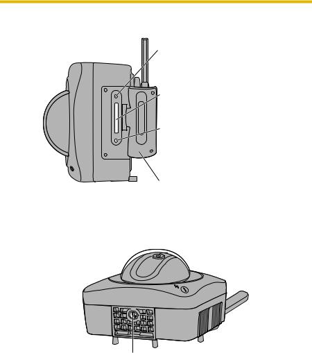
1.3Camera Feature Locations
1.3.1Front View
Antenna
Lens Cover
Lens (0.5 m [about 20 inches]—Unlimited)
Indicator
The indicator color shows camera status.
Microphone
The microphone picks up audio around the camera. (See page 29 of the Operating Instructions on the Setup CD-ROM)
Indicator Display
Power |
Not on the LAN |
Orange blinking |
|
||||||||
on |
On the LAN |
Orange blinking |
|
Green blinking |
|
|
Green |
||||
|
|
||||||||||
Normal Operation*1 |
|
|
Green |
|
|
|
|
||||
Automatic |
Setting |
Green blinking |
|
||||||||
Setup |
Finished setting |
Green blinking |
|
|
Green |
|
|||||
|
|
||||||||||
Using |
Getting IP address*2 |
Green blinking |
|
||||||||
DHCP |
Got IP address |
|
|
Green |
|
|
|
|
|||
Updating Firmware |
Orange blinking |
|
|||||||||
Pressing FACTORY |
Orange blinking |
|
|
Turning off |
|
||||||
|
|
|
|||||||||
DEFAULT RESET button |
(The camera restarts after that.) |
|
|||||||||
UPnPTM Failure |
Orange blinking (About a 2-second interval) |
||||||||||
Internal Failure |
Red blinking*3 |
|
|||||||||
*1 The indicator turns orange if the camera is not connected to the LAN. *2 The indicator blinks orange if the camera is not connected to the LAN. *3 See page 51.
12
Installation/Troubleshooting
1.3.2Side View
RESTART Button
Restarts the camera.
(see page 131 of the Operating Instructions on the Setup CD-ROM).
SD Memory Card Slot
(See page 40)
FACTORY DEFAULT RESET Button
Resets settings to default (see page 132 of the Operating Instructions on the Setup CD-ROM).
Cover
1.3.3Bottom View
Stand/Tripod Mounting Hole (See page 46 and page 48)
[For assistance, please call: 1-800-272-7033] |
13 |

Installation/Troubleshooting
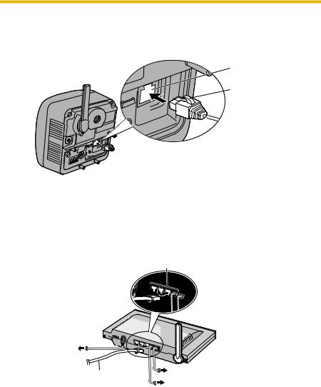
1.3.4Rear View
Antenna
Stand
Mounting Hole
(See page 47)
DC IN jack
(See page 16)
External I/O
(See page 129 of the Operating Instructions on the Setup CDROM))
Note
MAC Address (see page 18) and Serial number (S/ N) is indicated on the  label.
Ethernet® (LAN) port
(See page 15)
 Hook for Audio Cables
(See page 44)
Hook for Power Cord
(See page 44)
Audio Output Terminal
(See page 30 of the Operating Instructions on the Setup CD-ROM)
External Microphone Input Terminal
(See page 30 of the Operating Instructions on the Setup CD-ROM)
When installing the external microphone and external speaker outdoors, they must be for outdoor use.
14
Installation/Troubleshooting
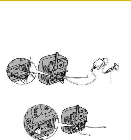
1.4Connecting the Camera to Your Router
Connect the camera to your router with an Ethernet cable to set up the camera.
1. Connect the Ethernet cable (customer-provided) to the camera.
Ethernet port
 Ethernet cable

 To your router
Note
These instructions assume your PC is already connected to the Internet and your network includes a router.
2. Connect the Ethernet cable to your router.
To a LAN port of your router
To the outlet |
Ethernet cable (Straight Cat5 cable) (Customer-provided)
To your modem
To your PC
[For assistance, please call: 1-800-272-7033] |
15 |
Installation/Troubleshooting
3.Connect the AC adaptor cord to the DC In jack, and plug the AC cord into the outlet.
•The AC cord is used as the main disconnect device, ensure that the socket-outlet is located/installed near the equipment and is easily accessible.
•Use only specified Panasonic AC adaptor PQLV202 (Order No. PQLV202W).
•If the indicator does not light green, see page 50 and page 51.
•A noise can be heard during pan/tilt operation. This is normal.
AC adaptor cord |
AC adaptor |
To Router 
AC cord
4. Hook the AC adaptor cord to the Hook for Power Cord.
16
Installation/Troubleshooting
1.5Setting up the Camera to View on the LAN
Setup CD-ROM allows you to easily set up the camera.
Notes
•To avoid any possible problems, temporarily disable any firewall or antivirus software.
•This procedure explains installation of the camera on the same network that your PC is part of.
•Before proceeding, close your web browser.
•See page 143 of the Operating Instructions on the Setup CD-ROM for details.
•To set the Wireless Configuration, the wireless LAN settings of your router—SSID, communication mode and encryption etc.—are required. (See your wireless router's manual for your reference to the wireless LAN settings.)
•When there are some cameras or PCs that are communicating wirelessly, the IP addresses may overlap and the camera may not be able to communicate. See page 144 of the Operating Instructions on the Setup CD-ROM.
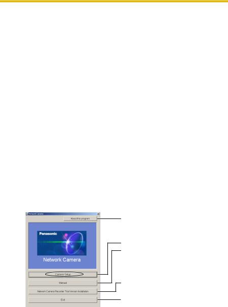
1.Insert the Setup CD-ROM into the CD-ROM drive of the PC.
•The window is automatically displayed.
(If the Network Camera Setup window is not displayed automatically, double-click "Setup.exe" file on the Setup CD-ROM.)
2.Click [Camera Setup].
Displays version information about this program.
Sets up the camera.
Displays the camera manuals.
If your PC does not have Adobe® Acrobat® Reader®, install it from the Adobe Reader website.
Installs Network Camera Recorder trial version. Closes the Setup Program.
[For assistance, please call: 1-800-272-7033] |
17 |
Installation/Troubleshooting
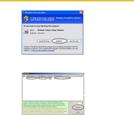
•When the following dialog box is displayed, click [Unblock].
3.Select the camera to set up and click [Execute].
•This program searches for the cameras that are connected to the router and displays the MAC Addresses, IP addresses and Port Numbers.
|
|
|
|
|
|
|
|
|
|
|
MAC |
|
|
|
|
|
|
|
|
|
|
Address |
|
Port |
Camera |
|||||||
|
|
IP |
No. |
Status |
||||||
|
|
|
|
|
|
|
|
|
Camera |
|
|
|
Address |
|
|
|
|
|
|||
|
|
|
|
|
|
|
List window |
|||
|
|
|
|
|
|
|
|
|
|
|
|
|
|
|
|
|
|
|
|
|
Displays IPv4 or |
|
|
|
|
|
|
|
|
|
|
|
|
|
|
|
|
|
|
|
|
|
IPv6 information. |
•The MAC Address on the rear side (see page 14) of the camera shows which camera you select on the Camera List window.
Notes
•If the indicator does not light green, check the connection. (See page 12)
•If more than 20 minutes have passed since the camera was turned on, the camera cannot be set up from the Setup Program. In this situation, disconnect the AC cord from the outlet, and reconnect it again.
•The Setup Program may not list any cameras due to your firewall or antivirus software settings on your PC. If you cannot disable your firewall or antivirus software, you can set up the camera entering the camera MAC address on the following window. The camera's MAC address can be found on the label affixed to the back of each camera. See page 33 for details.
18

Installation/Troubleshooting
4. Click [Automatic Setup (Local Access Only)].
•For the first time installation or after pressing the FACTORY DEFAULT RESET button, only [Automatic Setup (Local Access Only)] can be selected. To set up the camera with Static or DHCP settings, after performing the [Automatic Setup (Local Access Only)], run the Setup Program again and select [Manual Setup].
5.Enter the user name and password you wish to use, and click [Save].
[For assistance, please call: 1-800-272-7033] |
19 |
Installation/Troubleshooting
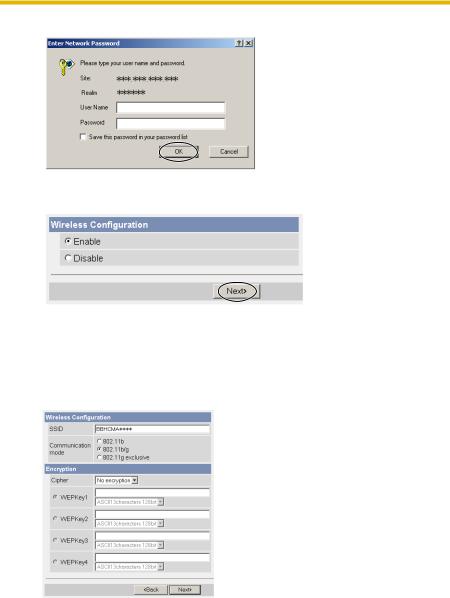
6. Enter the name and password that were entered above, and click [OK].
7.To set the Wireless Configuration, check [Enable] and click [Next>].
• When [Disable] was selected, skip to step 9.
•The Wireless Configuration can also be set at  in the Setup Page. (See page 61 of the Operating Instructions in the Setup CD-ROM.)
8.Set the Wireless Configuration according to the wireless settings of the router and click [Next>].
•See "Wireless Configuration" on page 27 for details of each item.
•Encryption is a help to avoid being read the data within wireless LAN by others.
•Enter both the MAC addresses for the camera itself and the camera's wireless module to enable the MAC address filtering feature on the wireless router. The wireless module MAC address is one value higher than the camera MAC address.
20
Installation/Troubleshooting
9.When the Single Camera page is displayed, the setup is completed.
•When Security Warning window is displayed, click [Yes]. (See page 38)
•See page 39 for Security Warning window when using Microsoft Windows XP Service Pack 2.
•When having set the wireless configuration, follow "1.7 Confirming the Wireless LAN Setup" on page 26.
Note
To ensure that the most current image is displayed, Internet Explorer should be configured as follows. This will not have any negative result on normal use.
1.While viewing any website, Click [Tools] [Internet Options].
2.In the section "Temporary Internet Files", click [Settings] and check [Every visit to the page].
To enable Internet access to the camera
Click [Next] to set up the Internet access to the camera and go to step 3 on the page 23.
•If you do not allow the Internet access, click [Cancel], and go to page 36 to confirm the camera image.
[For assistance, please call: 1-800-272-7033] |
21 |
Installation/Troubleshooting
1.6Setting up Internet Access to the Camera
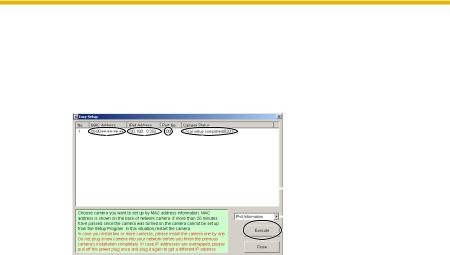
1.Display the Camera List window (see page 17—page 18).
2.Select the camera to set up and click [Execute].
•This program searches for the cameras that are connected to the router and displays the MAC Addresses, IP addresses and Port Numbers.
|
|
|
|
|
|
|
|
|
|
|
MAC |
|
|
|
|
|
|
|
|
|
|
Address |
|
Port |
Camera |
|||||||
|
|
IP |
No. |
Status |
||||||
|
|
|
|
|
|
|
|
|
Camera |
|
|
|
Address |
|
|
|
|
|
|||
|
|
|
|
|
|
|
List window |
|||
|
|
|
|
|
|
|
|
|
|
|
|
|
|
|
|
|
|
|
|
|
Displays IPv4 or |
|
|
|
|
|
|
|
|
|
|
|
|
|
|
|
|
|
|
|
|
|
IPv6 information. |
•The MAC Address on the rear side (see page 14) of the camera shows which camera you select on the Camera List window.
Note
If more than 20 minutes have passed since the camera was turned on, the camera cannot be set up from the Setup Program. In this situation, restart the camera.
22
Installation/Troubleshooting
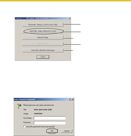
3. Click [Automatic Setup (Internet Access)].
Sets up the camera to view on the LAN.
Sets up the Internet access to the camera.
 Manually sets up the camera. Disables IPsec. If disabled, the button is displayed gray.
  Displays the Setup page (see page 39 of the Operating Instructions on the Setup CDROM).
Note
In order for Internet access to be properly enabled, your router’s UPnPTM feature should be enabled. Most router manufacturers disable this feature. See http://panasonic.co.jp/pcc/products/en/netwkcam/ for more information.
4. Enter the user name and password that were set, and click [OK].
[For assistance, please call: 1-800-272-7033] |
23 |

Installation/Troubleshooting
5.When using a router supporting UPnP™, check [Enable]. When using a router not supporting UPnP™, check [Disable]. Then click [Next].
•Check if your router supports UPnP™ referring to the router's manual. If UPnP™ is not supported, the router has to be manually configured for port forwarding. Refer to the router's manual for instruction on how to do it.
•If you select [Disable], skip to step 9.
6.To register with the "Viewnetcam.com FREE DDNS service", check [Register with Viewnetcam.com] and click [Next].
Viewnetcam.com FREE DDNS service
See page 29 for Viewnetcam.com information. For detailed information, access at http://www.viewnetcam.com.
•If you have multiple cameras, you can only register one camera for the Viewnetcam.com service.
•If you select [Disable], skip to step 9.
7.The Enter Network Password window is displayed, and enter the user name and password that were set, and click [OK].
8.After a while, the "Viewnetcam.com FREE DDNS service" website is displayed. Follow the displayed instructions for registration.
•If the message "Failed to configure the router's Port Forwarding by UPnP" is displayed, your router may not support UPnPTM or UPnPTM is not enabled. Enable your router's UPnPTM or set Port Forwarding manually following the router's manual and try Automatic Setup again. For more information about setting up a router, refer to the Panasonic Network Camera support website at http://panasonic.co.jp/pcc/products/en/ netwkcam/.
•If the message "Failed to register with Viewnetcam.com." is displayed, confirm that the router is connected to the Internet.
24
Installation/Troubleshooting
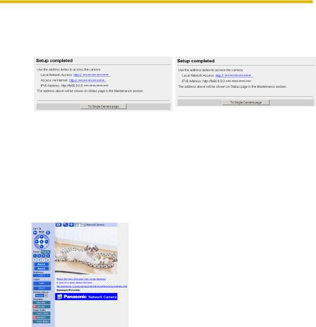
9. When "Setup complete" is displayed, and click [To Single Camera page].
• When [Enable] was selected at • |
When [Disable] was selected |
step 5 |
at step 5 |
•The port number must be specified at the end of camera URL.
Using port 80: http://(Cameraname).viewnetcam.com or http://IP Address
Using any other port: http://(Cameraname).viewnetcam.com:Port Number or http://IP Address:Port Number
10.When the Single Camera page is displayed, the setup is completed.
Notes
•The banner is displayed only when Internet access is allowed on the camera.
•To ensure that the most current image is displayed, Internet Explorer should be configured as follows. This will not have any negative result on normal use.
1.While viewing any website, Click [Tools] [Internet Options].
2.In the section "Temporary Internet Files", click [Settings] and check [Every visit to the page].
[For assistance, please call: 1-800-272-7033] |
25 |
Installation/Troubleshooting
1.7Confirming the Wireless LAN Setup
After setting each item for the wireless LAN, confirm that the camera works correctly.
1.Turn off the power.
2.Disconnect the Ethernet cable.
3.Turn on the power
• Confirm that the indicator lights green.
Note
If the indicator does not light green, the radio waves may not be reaching the camera. Put the camera near the wireless router. Or the SSID or the WEP key may be different from those for the wireless router.
4.Start up the web browser on the PC.
5.Enter "http://IP address (or URL):Port No." in the address field and press [Enter].
(When port number is 80 (default), you do not need to enter port number.)
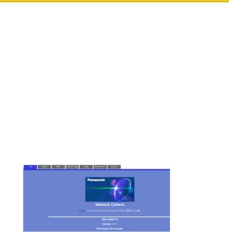
6.When the following Top Page is displayed, the wireless LAN setup is successful.
•If the Top Page was not displayed, the settings for the camera are not identical with those for the router. Check the settings by using wired connection.
If the settings are correct and you use a proxy server, set the web browser not to access the proxy server.
If the Top Page is not displayed even after trying these methods, contact the retailer.
•It takes about 1 minute for the new settings to be effective.
•It is not possible to access the camera simultaneously by both wired and wireless connection.
•Some wireless routers need to be restarted.
26

Installation/Troubleshooting
1.7.1Wireless Configuration
Set the Wireless Configuration according to the wireless settings of the router.
•For more information about wireless setting, see http://panasonic.co.jp/pcc/products/en/netwkcam/
1
2
3
4
1.Set the SSID.
Set the name of the wireless network.
2.Select the Communication mode.
They are IEEE Communication modes. Select the same Communication mode as that of the router to which the camera is connected.
802.11b (IEEE802.11b) |
: Only 802.11b wireless router can |
|
be connected. |
802.11b/g (IEEE802.11g) |
: Either 802.11b or 802.11g router |
|
can be connected. |
802.11g exclusive |
: Only 802.11g router can be |
(IEEE802.11g) |
connected. |
3.Select encrypting or not encrypting.
Selecting WEP can encrypt data within the wireless LAN.
WEP |
: Encrypting (setting WEP) makes it difficult for |
|
unauthorized users to read data within the wireless |
|
LAN, even if they can receive it. To encrypt data, set |
|
the same encryption key to every terminal within the |
|
wireless LAN. There are 3 kinds of encryption key: |
|
64 bit, 128 bit and 152 bit. Security level of |
|
encryption increases in order of length as follows: 64 |
|
bit, 128 bit and 152 bit. |
No encryption : select when not using encryption.
[For assistance, please call: 1-800-272-7033] |
27 |

Installation/Troubleshooting
4.Set the WEPKey1–4.
Selecting [WEP] at Cipher enables you to set WEPKey1–4. One or all of the four keys can be set. Check the same key number as set to the router, and set the same key as at the router.
: The entered WEPKey will be displayed as " "s regardless of the key type selected.
<Example> |
|
HEX, 10 characters 64 bit |
: 012345abcd |
HEX, 26 characters 128 bit |
: 0123456789abcdef012345abcd |
HEX, 32 characters 152 bit |
: 0123456789abcdef0123456789abcdef |
ASCII 5 characters 64 bit |
: 012yz |
ASCII 13 characters 128 bit |
: 0123456uvwxyz |
ASCII 16 characters 152 bit |
: 0123456789uvwxyz |
Note
Make sure to set Encryption to secure the wireless LAN.
28
Installation/Troubleshooting
1.8Viewnetcam.com Service (IPv4/IPv6)
Viewnetcam.com is a free dynamic DNS (DDNS) service provided by Panasonic. It allows you to choose an easy-to-remember address (such as "bob.viewnetcam.com") that you can use to view images from your camera over the Internet. This service is compatible with both IPv4 and IPv6 addresses.
What is the advantage of Viewnetcam.com service?
In order to view camera images over the Internet, you need to know your camera’s global IP address. However, many Internet Service Providers (ISPs) assign their customers a "dynamic" IP address that changes monthly, weekly, or each time they log on. Unless you have been assigned a static IP address (an IP address that does not change periodically) by your ISP, you may find it difficult to access your camera over the Internet because your IP address changes periodically. Viewnetcam.com service allows you to access your camera even if your assigned global IP address changes.
See http://www.viewnetcam.com for details.
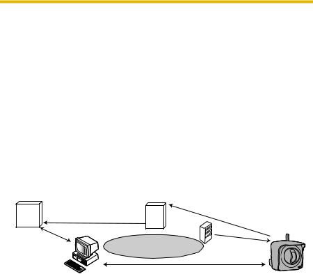
How the Viewnetcam.com service works
Viewnetcam.com service server
DNS
3. New address registered with
server
DNS server
ISP
4. DNS looks up |
Internet |
current address |
2. Camera reports new address
On-site Network Camera
1. Global IP address  changes
5. Camera connection established
Off-site PC
1.Your ISP assigns a global IP address to your Internet access account that changes periodically. This is the address needed to access the camera over the Internet.
2.When your ISP assigned global IP address changes, your camera automatically notifies the Viewnetcam.com service server of the new address.
3.The Viewnetcam.com server contacts a Domain Name Server (DNS) and registers your new global IP address to your chosen Viewnetcam.com address (such as "bob.viewnetcam.com").
4.When you enter your Viewnetcam.com address in your web browser while away from home or the office, the DNS server looks up the global IP address assigned to your Viewnetcam.com address.
5.The DNS server finds your current global IP address and allows you to connect to your camera.
[For assistance, please call: 1-800-272-7033] |
29 |

Installation/Troubleshooting
Notes
•Ask your ISP about what type of IP address you are using.
•Some ISPs assign you a local IP address. In this case, you cannot use the Viewnetcam.com service. Ask you ISP about what type of IP address you are using.
•If the camera is using a port number other than 80, the port number must be specified at the end of the Viewnetcam URL. For example:
Using port 80: http://(Cameraname).viewnetcam.com
Using any other port: http://(Cameraname).viewnetcam.com:Port
Number
30
 Loading...