


AW-RP120G
Table of contents
 Loading...
Operating Instructions
<Basics>
Remote Camera Controller
ModelNo.
z Die Bedienungsanleitung in Deutsch ist als PDF-Datei in der CD-ROM enthalten.
z Le mode d’emploi en français est fourni sous forme de fichier PDF sur le CD-ROM.
z Le istruzioni per l’uso in italiano sono contenute in un file PDF sul CD-ROM.
z Las instrucciones de funcionamiento en español se encuentran en un archivo PDF del CD-ROM.
z Документ Инструкция по эксплуатации на русском языке находится в виде PDF-файла на диске CD-ROM.
z 日本語の取扱説明書は、PDFファイル形式でCD-ROMに納められています。
REMOTE CAMERA CONTROLLER AW-RP120
AW-RP120G
Beforeoperatingthisproduct,pleasereadtheinstructionscarefullyandsavethismanualforfutureuse.
HowtheOperatingInstructionsareconfigured
<Basics> (thismanual):
This<Basics>describestheprocedureforconnectionwiththerequiredequipmentandforinstallation.
Beforeinstallingthisunit,besuretotakethetimetoreadthrough<Basics>toensurethattheunitwill
beinstalledcorrectly.
Thismanual<Basics>isalsocontainedasaPDFfileontheCD-ROMsuppliedwiththeunit.
<Operations and Settings>:
The<OperationsandSettings>describeshowtooperatetheunitandhowtoestablishitssettings.
The<OperationsandSettings>iscontainedasaPDFfileontheCD-ROMsuppliedwiththeunit.
SS0113HO0-FJ
PrintedinJapan
ENGLISH
VQT4T93(E)

ENGLISH
p How to open the operating instruction manual PDF
files
Discontinue installation if the installation screen of the
software opens as a result of inserting the CD-ROM.
When [INDEX.pdf] on the CD-ROM is opened, a list of
the operating instruction manuals will be displayed.
Click on the document name of the manual to be opened.
p Adobe
®
Reader® is required to read PDF files.
It can be downloaded from the home page of Adobe
Systems.
DEUTSCH
p Öffnen der PDF-Dateien der Bedienungsanleitung
Brechen Sie die Installation ab, falls beim Einlegen
der CD-ROM der Installationsbildschirm der Software
erscheint.
Wenn [INDEX.pdf] auf der CD-ROM geöffnet wird,
erscheint eine Liste der Bedienungsanleitungen.
Klicken Sie auf den Dokumentennamen der zu öffnenden
Anleitung.
p Zum Lesen der PDF-Dateien benötigen Sie Adobe
Reader
®
.
Dieses Programm kann von der Homepage von
Adobe Systems heruntergeladen werden.
FRANÇAIS
p Comment ouvrir les fichiers PDF des manuels du
mode d’emploi
Arrêter l’installation si l’écran d’installation du logiciel
s’ouvre quand le CD-ROM est inséré.
Quand [INDEX.pdf] sur le CD-ROM s’ouvre, la liste des
manuels du mode d’emploi s’affiche.
Cliquer sur le nom du document correspondant au
manuel à consulter.
p Adobe
®
Reader® est nécessaire pour lire les fichiers
PDF.
Ce logiciel peut être téléchargé depuis la page
d’accueil d’Adobe Systems.
ESPAÑOL
p Modo de abrir los archivos PDF que contienen el
manual de las instrucciones de funcionamiento
Interrumpa la instalación si la pantalla de instalación del
software se abre como resultado de insertar el CD-ROM.
Cuando se abra [INDEX.pdf] en el CD-ROM se
visualizará una lista de los manuales de instrucciones de
funcionamiento.
Haga clic en el nombre de documento del manual que va
a abrir.
p Para leer los archivos PDF se necesita el programa
®
Adobe
Reader®.
Este programa se puede descargar de la página
inicial de Adobe Systems.
РУССКИЙ
p Как открыть PDF-файлы инструкции по
эксплуатации
Прекратите установку, если в результате загрузки
диска CD-ROM появилось окно установки
программного обеспечения.
®
При открытии файла [INDEX.pdf] на диске CD-ROM
будет отображен список инструкций по эксплуатации.
Щелкните название документа руководства, чтобы
открыть его.
p Для чтения PDF-файлов потребуется Adobe
Reader
®
.
®
p Данное программное обеспечение можно скачать
с домашней страницы Adobe Systems.
取扱説明書PDFファイルの開き方
CD-ROMを挿入してソフトウェアのインストール画面が
立ち上がる場合は、インストールを中止してください。
CD-ROM内の[INDEX.pdf]を開くと取扱説明書の一覧が表
示されます。
開きたい取扱説明書のドキュメント名をクリックしてく
ださい。
®
PDFファイルをご覧いただくには、Adobe
Reader®が
必要です。
アドビシステムズ社のホームページからダウンロードし
てください。
ITALIANO
p Come aprire i file dei manuali di istruzioni per l’uso
Se inserendo il CD-ROM si apre la schermata di
installazione del software, interrompere l’installazione.
Aprendo [INDEX.pdf] sul CD-ROM, viene visualizzato un
elenco di manuali di istruzioni per l’uso.
Fare clic sul nome del documento corrispondente al
manuale da aprire.
p Per leggere i file PDF è necessario Adobe
Il programma può essere scaricato dal sito Web di
Adobe Systems.
®
Reader®.
2

Read this first!
WARNING:
• To reduce the risk of fire, do not expose this
equipment to rain or moisture.
• To reduce the risk of fire, keep this equipment away
from all liquids.
Use and store only in locations which are not
exposed to the risk of dripping or splashing liquids,
and do not place any liquid containers on top of the
equipment.
WARNING:
Always keep memory cards or accessories out of the
reach of babies and small children.
WARNING:
Installation should only be performed by qualified
installation personnel. Improper installation may result
in the entire apparatus falling down and causing injury.
indicates safety information.
CAUTION:
Do not remove panel covers by unscrewing.
To reduce the risk of electric shock, do not remove the
covers. No user serviceable parts inside.
Refer servicing to qualified service personnel.
CAUTION:
To reduce the risk of fire or electric shock and
annoying interference, use the recommended
accessories only.
CAUTION:
In order to maintain adequate ventilation, do not install
or place this unit in a bookcase, built-in cabinet or any
other confined space. To prevent risk of electric shock
or fire hazard due to overheating, ensure that curtains
and any other materials do not obstruct the ventilation.
FCC NOTICE (USA)
This device complies with part 15 of the FCC Rules.
Operation is subject to the following two conditions:
(1) This device may not cause harmful interference, and (2) this device must accept any interference received,
including interference that may cause undesired operation.
FCC Note:
This equipment has been tested and found to comply with the limits for a class A digital device, pursuant to Part 15
of the FCC Rules. These limits are designed to provide reasonable protection against harmful interference when
the equipment is operated in a commercial environment. This equipment generates, uses, and can radiate radio
frequency energy, and if not installed and used in accordance with the instruction manual, may cause harmful
interference to radio communications. Operation of this equipment in a residential area is likely to cause harmful
interference in which case the user will be required to correct the interference at his own expense.
Warning:
To assure continued FCC emission limit compliance, the user must use only shielded interface cables when
connecting to external units. If DVI-D port is to be used it must be connected to PC by compatible interface cable with
two ferrite cores. Also, any unauthorized changes or modifications to this equipment could void the user’s authority to
operate it.
NOTIFICATION (Canada)
This class A digital apparatus complies with Canadian ICES-003.
indicates safety information.
3

Read this first! (continued)
IMPORTANT SAFETY INSTRUCTIONS
1) Read these instructions.
2) Keep these instructions.
3) Heed all warnings.
4) Follow all instructions.
5) Do not use this apparatus near water.
6) Clean only with dry cloth.
7) Do not block any ventilation openings. Install in accordance with the manufacturer’s instructions.
8) Do not install near any heat sources such as radiators, heat registers, stoves, or other apparatus (including amplifiers)
that produce heat.
9) Do not defeat the safety purpose of the polarized or grounding-type plug. A polarized plug has two blades with one wider
than the other. A grounding-type plug has two blades and a third grounding prong. The wide blade or the third prong are
provided for your safety. If the provided plug does not fit into your outlet, consult an electrician for replacement of the
obsolete outlet.
10) Protect the power cord form being walked on or pinched particularly at plugs, convenience receptacles, and the point
where they exit from the apparatus.
11) Only use attachments/accessories specified by the manufacturer.
12) Use only with the cart, stand, tripod, bracket, or table specified by the manufacturer, or sold with the
apparatus. When a cart is used, use caution when moving the cart/apparatus combination to avoid injury
from tip-over.
13) Unplug this apparatus during lightning storms or when unused for long periods of time.
14) Refer all servicing to qualified service personnel. Servicing is required when the apparatus has been damaged in any
way, such as power-supply cord or plug is damaged, liquid has been spilled or objects have fallen into the apparatus, the
apparatus has been exposed to rain or moisture, does not operate normally, or has been dropped.
EEE Yönetmeliğine Uygundur.
EEE Complies with Directive of Turkey.
4

Read this first! (continued)
EMC NOTICE FOR THE PURCHASER/USER OF THE APPARATUS
1. Applicable standards and operating environment (AW-RP120G)
The apparatus is compliant with:
• standards EN55103-1 and EN55103-2, and
• electromagnetic environments E1, E2, E3, E4 and E5.
2. Pre-requisite conditions to achieving compliance with the above standards
<1> Peripheral equipment to be connected to the apparatus and special connecting cables
• The purchaser/user is urged to use only equipment which has been recommended by us as peripheral equipment
to be connected to the apparatus.
• The purchaser/user is urged to use only the connecting cables described below.
<2> For the connecting cables, use shielded cables which suit the intended purpose of the apparatus.
• Video signal connecting cables
Use double shielded coaxial cables, which are designed for 75-ohm type high-frequency applications, for SDI
(Serial Digital Interface).
Coaxial cables, which are designed for 75-ohm type high-frequency applications, are recommended for analog
video signals.
• Audio signal connecting cables
If your apparatus supports AES/EBU serial digital audio signals, use cables designed for AES/EBU.
Use shielded cables, which provide quality performance for high-frequency transmission applications, for analog
audio signals.
• Other connecting cables (LAN, RS-422)
Use double shielded cables, which provide quality performance for high-frequency applications, as connecting
cables.
• When connecting to the DVI signal terminal, use a cable with a ferrite core.
• If your apparatus is supplied with ferrite core(s), they must be attached on cable(s) following instructions in this
manual.
3. Performance level
The performance level of the apparatus is equivalent to or better than the performance level required by these standards.
However, the apparatus may be adversely affected by interference if it is being used in an EMC environment, such as an
area where strong electromagnetic fields are generated (by the presence of signal transmission towers, cellular phones,
etc.). In order to minimize the adverse effects of the interference on the apparatus in cases like this, it is recommended
that the following steps be taken with the apparatus being affected and with its operating environment:
1. Place the apparatus at a distance from the source of the interference.
2. Change the direction of the apparatus.
3. Change the connection method used for the apparatus.
4. Connect the apparatus to another power outlet where the power is not shared by any other appliances.
Декларація про Відповідність
Вимогам Технічного Регламенту Обмеження Використання деяких Небезпечних Речовин в
електричному та електронному обладнанні
(затвердженого Постановою №1057 Кабінету Міністрів України)
Виріб відповідає вимогам Технічного Регламенту Обмеження Використання деяких Небезпечних Речовин в електричному та
електронному обладнанні (ТР ОВНР).
Вміст небезпечних речовин у випадках, не обумовлених в Додатку №2 ТР ОВНР, :
1. свинець(Pb) – не перевищує 0,1 % ваги речовини або в концентрації до 1000 частин на мільйон;
2. кадмій (Cd)– не перевищує 0,01 % ваги речовини або в концентрації до 100 частин на мільйон;
3. ртуть(Hg) – не перевищує 0,1 % ваги речовини або в концентрації до 1000 частин на мільйон;
4. шестивалентний хром (Cr
5. полібромбіфеноли (PBB) – не перевищує 0,1% ваги речовини або в концентрації до 1000 частин на мільйон;
6. полібромдефенілові ефіри (PBDE) – не перевищує 0,1 % ваги речовини або в концентрації до 1000 частин на мільйон.
6+
) – не перевищує 0,1 % ваги речовини або в концентрації до 1000 частин на мільйон;
Importer’snameandaddressofpursuanttoEUrules:
Panasonic Testing Centre
Panasonic Marketing Europe GmbH
Winsbergring15,22525Hamburg,Germany
5

Contents
Read this first! . . . . . . . . . . . . . . . . . . . . . . . . . . . . . . . . . . . . . . . . . . . .3
Introduction . . . . . . . . . . . . . . . . . . . . . . . . . . . . . . . . . . . . . . . . . . . . . . 7
Features . . . . . . . . . . . . . . . . . . . . . . . . . . . . . . . . . . . . . . . . . . . . . . . . . 8
Supported remote cameras . . . . . . . . . . . . . . . . . . . . . . . . . . . . . . . . . 8
Supported switcher . . . . . . . . . . . . . . . . . . . . . . . . . . . . . . . . . . . . . . . . 8
Accessories . . . . . . . . . . . . . . . . . . . . . . . . . . . . . . . . . . . . . . . . . . . . . .9
Precautions for use . . . . . . . . . . . . . . . . . . . . . . . . . . . . . . . . . . . . . . . . 9
Precautions for installation . . . . . . . . . . . . . . . . . . . . . . . . . . . . . . . . 10
Appearance . . . . . . . . . . . . . . . . . . . . . . . . . . . . . . . . . . . . . . . . . . . . . 11
Parts and their functions . . . . . . . . . . . . . . . . . . . . . . . . . . . . . . . . . . 12
Control panel . . . . . . . . . . . . . . . . . . . . . . . . . . . . . . . . . . . . . . . . . . . 12
Rear panel . . . . . . . . . . . . . . . . . . . . . . . . . . . . . . . . . . . . . . . . . . . . . 18
Basic operations of the unit . . . . . . . . . . . . . . . . . . . . . . . . . . . . . . . . 19
Basic operations for the menus . . . . . . . . . . . . . . . . . . . . . . . . . . . . . 20
Connections . . . . . . . . . . . . . . . . . . . . . . . . . . . . . . . . . . . . . . . . . . . . . 21
Examples of IP connections . . . . . . . . . . . . . . . . . . . . . . . . . . . . . . . 21
Examples of serial connections . . . . . . . . . . . . . . . . . . . . . . . . . . . . . 23
Network settings of the unit . . . . . . . . . . . . . . . . . . . . . . . . . . . . . . . . 27
Settings for connecting with the remote cameras and switcher . . 29
Setting the connection types for remote cameras
(serial/IP/no connection) . . . . . . . . . . . . . . . . . . . . . . . . . . . . . . . . 30
Setting the connection type (IP/no connection) for the switcher . . . . 30
Setting the IP addresses automatically (auto IP setting) . . . . . . . . . . 30
Swapping connection destination IP addresses . . . . . . . . . . . . . . . . 35
Manually setting the connection destination IP addresses
(remote cameras) . . . . . . . . . . . . . . . . . . . . . . . . . . . . . . . . . . . . . 35
Setting the connection destination port number . . . . . . . . . . . . . . . . 36
Manually setting the connection destination IP address (switcher) . . 36
Initializing the connection destination IP addresses set
on the unit . . . . . . . . . . . . . . . . . . . . . . . . . . . . . . . . . . . . . . . . . . . 36
Selecting a camera group . . . . . . . . . . . . . . . . . . . . . . . . . . . . . . . . . . 37
Selecting a remote camera . . . . . . . . . . . . . . . . . . . . . . . . . . . . . . . . . 38
Troubleshooting . . . . . . . . . . . . . . . . . . . . . . . . . . . . . . . . . . . . . . . . . 39
Specifications . . . . . . . . . . . . . . . . . . . . . . . . . . . . . . . . . . . . . . . . . . . 40
Index . . . . . . . . . . . . . . . . . . . . . . . . . . . . . . . . . . . . . . . . . . . . . . . . . . . 41
About trademarks and registered trademarks
Microsoft®, Windows®, Windows® 7, and Internet Explorer® are registered
trademarks or trademarks of Microsoft Corporation in the United States,
Japan, and/or other countries.
®
and Intel® CoreTM are trademarks or registered trademarks of Intel
Intel
Corporation and its subsidiaries in the United States and/or other countries.
®
and Reader® are registered trademarks or trademarks of Adobe
Adobe
Systems Incorporated in the United States and/or other countries.
SDHC logo is a trademark of SD-3C, LLC.
Other company names and product names appearing in this manual are
the registered trademarks or trademarks of their respective companies.
Copyrights
It is prohibited to transfer, copy, disassemble, decompile, and reverse
engineer the software included with the unit, as well as export it in
violation of the export laws.
Illustrations and screen images in this manual
Illustrations of the unit and screens may appear different from the actual
unit and screens.
Protection of personal information
Image information of identifiable individuals that is recorded with a
system using this unit is subject to the Act on the Protection of Personal
Information.*
Be sure to handle image information in accordance with the law.
* Please refer to “Cases corresponding to personal information” in
“Guidelines Targeting Economic and Industrial Sectors Pertaining to the
Act on the Protection of Personal Information” published by the Ministry
of Economy, Trade and Industry.
Abbreviations
The following abbreviations are used in this manual.
Microsoft® Windows® 7 Professional SP1 32/64-bit is referred to as
“Windows 7”.
®
Microsoft
Microsoft
“Windows XP”.
SD memory cards and SDHC memory cards are both referred to as
“memory cards”.
They are referred to individually in descriptions in which each of them is
discussed separately.
In these instructions, the phrases “HD integrated camera” and “pan-tilt
head and camera combination” are referred to collectively as “remote
camera” except in places where specific equipment is mentioned.
Furthermore, the product numbers of equipment are referred to as
follows.
Equipment part
AW-HS50N AW-HS50 AK-HC1500G AK-HC1500
AW-RP50N AW-RP50 AK-HC1800G AK-HC1800
AW-HE50HN
AW-HE50SN AW-HE870N AW-HE870
AW-HE60HN
AW-HE60SN AW-PH405N AW-PH405
AW-HE120W
AW-HE120K AW-IF400G AW-IF400
AW-HE100N AW-HE100
Windows® XP Professional SP3 and
®
Windows® XP Home Edition SP3 are referred to as
number
Notation in
this manual
AW-HE50
AW-HE60
AW-HE120
Equipment part
number
AW-E860N AW-E860
AW-PH360N AW-PH360
AW-PH650N AW-PH650
Notation in
this manual
6

Introduction
Overview
This unit is a controller which is designed to control remote cameras.
It can be used to control up to 100 remote cameras when IP connections
are used, and up to 5 remote cameras when serial connections are
used.
Also, operation linked to an AW-HS50 compact live switcher can be
implemented by means of an IP connection.
Required personal computer environment
Run the software that is supplied with the unit on a personal computer
which satisfies the following specifications.
CPU Intel® CoreTM2 Duo 2.4 GHz or faster, or a CPU with
Memory Windows XP: 512 MB or more
Network function 10BASE-T or 100BASE-TX
Image display
function
Supported
operating systems
Hard disk drive At least 50 MB of free space
Other CD-ROM drive
equivalent specs.
Windows 7: 1 GB or more
Resolution: 1024768 pixels or more
Color generation: True Color (24 bits or more)
Windows XP
Windows 7
(For using the Operating Instructions and various
software)
®
®
Reader
Adobe
(For browsing the Operating Instructions on the
CD-ROM)
Network security
As you will use this unit connected to a network, your attention is called
to the following security risks.
(1) Leakage or disclosure of information transmitted via this unit
(2) Unauthorized use of this unit by a third person with malicious
intent
(3) Interference or stoppage of this unit by a third person with
malicious intent
It is your responsibility to take sufficient network security measures such
as those described below to protect yourself against the above risks.
Use this unit in a network secured by a firewall, etc.
If this unit is used in a system with a computer connected, make
sure that checks for and removal of computer viruses and malicious
programs are implemented regularly.
Do not install the unit in a location where the unit, cables, and other
parts may be easily damaged.
User authentication
The user authentication function of this unit uses basic authentication.
When basic authentication is used on an unsecured network, there is
the risk of passwords being leaked.
We recommend using host authentication in such a case.
Configure the host authentication settings on the remote cameras. For
details, refer to the operating instructions for the remote cameras.
Restrictions on use
With regards to the network for connecting the remote cameras and
personal computer to the unit, we recommend that the segment is the
same.
If there are connections for which the segment is different, events
dependent upon, for example, settings unique to the network equipment
may occur so carefully check the connections prior to the start of
operation.
Disclaimer of warranty
IN NO EVENT SHALL Panasonic Corporation BE LIABLE TO ANY
PARTY OR ANY PERSON, EXCEPT FOR REPLACEMENT OR
REASONABLE MAINTENANCE OF THE PRODUCT, FOR THE
CASES, INCLUDING BUT NOT LIMITED TO BELOW:
(1) ANY DAMAGE AND LOSS, INCLUDING WITHOUT LIMITATION,
DIRECT OR INDIRECT, SPECIAL, CONSEQUENTIAL OR
EXEMPLARY, ARISING OUT OF OR RELATING TO THE
PRODUCT;
(2) PERSONAL INJURY OR ANY DAMAGE CAUSED BY
INAPPROPRIATE USE OR NEGLIGENT OPERATION OF THE
USER;
(3) UNAUTHORIZED DISASSEMBLE, REPAIR OR MODIFICATION
OF THE PRODUCT BY THE USER;
(4) INCONVENIENCE OR ANY LOSS ARISING WHEN IMAGES
ARE NOT DISPLAYED, DUE TO ANY REASON OR CAUSE
INCLUDING ANY FAILURE OR PROBLEM OF THE PRODUCT;
(5) ANY PROBLEM, CONSEQUENTIAL INCONVENIENCE,
OR LOSS OR DAMAGE, ARISING OUT OF THE SYSTEM
COMBINED BY THE DEVICES OF THIRD PARTY;
(6) ANY INCONVENIENCE, DAMAGES OR LOSSES RESULTING
FROM ACCIDENTS CAUSED BY AN INADEQUATE
INSTALLATION METHOD OR ANY FACTORS OTHER THAN A
DEFECT IN THE PRODUCT ITSELF;
(7) LOSS OF REGISTERED DATA CAUSED BY ANY FAILURE;
(8) ANY DAMAGE OR CLAIMS DUE TO LOSS OR LEAKAGE OF
IMAGE DATA OR SETTING DATA SAVED ON THIS UNIT OR ON
A MEMORY CARD OR COMPUTER.
7

Features
IP connections and serial connections supported
IP connections
Up to 100 remote cameras
(switching hub).
The unit’s auto IP setting function can be used to automatically
assign and control the IP addresses of the remote cameras
*2
switcher
*1: Supported cameras: AW-HE50, AW-HE60, AW-HE120, and AW-HE2
*2: Supported switcher: AW-HS50
One remote camera can be simultaneously controlled from up to 5
units.
The setup software supplied with this unit can be used to set the IP
addresses of the remote cameras and switchers from a personal
computer via the unit.
Serial connections
Up to 5 remote cameras can be connected.
.
*1
can be controlled via a network hub
*1
and
Easy to operate the remote cameras
Supported remote cameras
HD integrated cameras
AW-HE50, AW-HE60, AW-HE120, AW-HE100, and AW-HE2
*3: Some operations of the AW-HE2 differ from those of other HD integrated cameras.
For details, refer to “Operations of AW-HE2” in Operations and Settings (page 51).
*3
The unit is equipped with dedicated levers, buttons, and dials for
performing pan, tilt, zoom, and focus operations. Furthermore,
there is a dedicated speed adjustment knob for each of them.
Camera angle adjustment can be performed quickly and reliably.
The unit is equipped with an AWB button and ABB button for
executing automatic adjustment of the white balance and black
balance. Furthermore, there are dedicated dials for adjusting the
pedestal and gain for each of the R channel and B channel.
Manual color adjustment is also easy.
The 1 to 50 number buttons and page buttons enable quick access
operations at sites where preset settings are used frequently.
Also, a playback speed can be assigned to each preset number to
enable video to be played at a variety of speeds.
Tracing memory is incorporated for recording a series of
operations.
It allows you to duplicate remote camera operations.
Pan-tilt head and camera combinations
Systems including a combination of any of the following pan-tilt heads and cameras can be controlled.
Pan-tilt heads
AW-PH360, AW-PH405, AW-PH650, and AW-PH400*
*: AW-IF400 is required to connect AW-PH400 to the unit.
Cameras
AW-HE870, AW-E860, AW-E750, AW-E650, AW-E350, AK-HC1500, and AK-HC1800
Supported switcher
Compact live switcher
AW-HS50
8

Accessories
Check the accessories.
After unpacking the product, dispose of the packaging material appropriately.
CD-ROM .......................... 1
Operating Instructions <Basics>
Operating Instructions <Operations and Settings>
Setup software
Precautions for use
Observe the following in addition to the information included in “Read this first!”.
Handle carefully
Do not drop the product, or subject it to a strong impact or vibration.
Do not carry or move the product by the PAN/TILT lever or a dial.
Doing so may cause a failure or accident.
Use the product in an ambient temperature of 0 °C to 40 °C
(32 °F to 104 °F)
Avoid using the product in a cold place where the temperature drops
below 0 °C (32 °F) or in a hot place where the temperature rises above
40 °C (104 °F) because an extremely low or high temperature will
adversely affect the internal parts.
Turn off the power before connecting or disconnecting
cables
Before connecting or disconnecting the cables, be sure to turn the power
off.
Avoid humidity and dust
Avoid using the product in a very humid or dusty place because a lot of
humidity and dust will cause damage to the internal parts.
Cleaning
Turn the power off and wipe the product with a dry cloth. To remove
stubborn dirt, dip a cloth into a diluted solution of kitchen detergent
(neutral detergent), wring it out well, and wipe the product gently.
Then, wipe the product with a cloth dampened with water. Finally, wipe
the product with a dry cloth.
Notes
Avoid using benzine, paint thinners and other volatile fluids.
If a chemical cleaning cloth is to be used, carefully read through
the precautions for its use.
Disposal of the unit
When the unit has reached the end of its service life and is to be
disposed of, ask a qualified contractor to dispose of the unit properly in
order to protect the environment.
9
Precautions for installation
In addition to the safety precautions given in “Read this first!”, also observe the following instructions.
Be sure to ask your dealer to perform the installation and connection work for the unit.
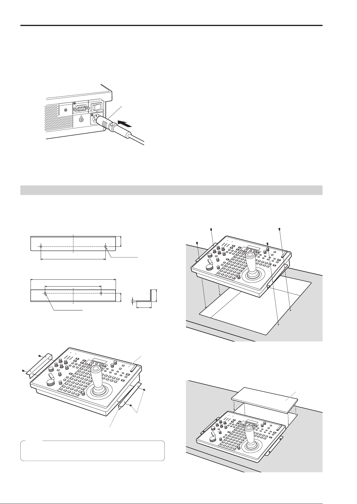
Connecting a power supply
Do not allow any foreign objects to enter inside the unit
Insert the DC plug for the external DC power supply all the way in
until it locks into place.
Installation location
LCD CONTRAS T
SIGNAL GN D
ON
12V IN
DC plug
POWER
REMOTE
When the unit will not be used for a long time, turn off the power
switch and remove the DC plug for the external DC power supply to
save power.
Example of embedding the unit in a desktop
When you will use the unit embedded in a desktop, refer to the following procedure.
1. Make mount angles suitable for the installation location.
<Mount angle example>
Desk mounting side (unit: mm (inch))
3. Insert the unit into the desktop hole and then fix it in
Allowing water, metal items, food or drink, or other foreign objects to
enter inside the unit may cause a fire or electric shock.
This unit is designed for indoor use only.
Install and use the unit in a stable location.
Avoid installing the unit where it will be exposed to direct sunlight.
Installing the unit in a location with a lot of humidity, dust, or vibration
may result in a failure.
place with four screws
25 (0000)
160 (0000)
Unit mounting side
210 (0000)
140 (0000)
Ø3.5 (0000)
(Unit mounting hole)
Ø5 (0000)
(Desk mounting holes)
21
1.2 (0000)
(0000)
35
(0000)
2. Attach the mount angles to the sides of the unit with
four M3 screws.
Unit
30
(0000)
Provide screws that match the size of the desktop mounting holes
(e.g. Ø5 mm (00 inches)).
4. If necessary, make and attach a panel to cover the rest
of desktop hole.
Panel to cover hole
M3 screws
Mount angle
Note
For details on the dimensions for attaching mount angles to the
unit, refer to “Appearance” (page 11).
10

Appearance
Unit: mm (inch)
317.2 (0000)
77 (0000)
342 (0000)
Mount angle attachment position
52.5 (0000)
12.4 (0000)
265 (0000)
54 (0000)
161 (0000)
2-M3
17 (0000)
51
(0000)
140 (0000)
249.6 (0000)
39
(0000)
74.3 (0000)
11

Parts and their functions
Control panel
Indicator section
Color adjustment
section
Menu operation section Memory card section
User button section
Camera selection
section
Pan and tilt section
Focus, zoom and iris section Menu and memory selection section
POWER indicator [POWER]
1
This turns on when the POWER switch () on the rear panel is set to
ON while power is supplied to the DC IN socket ().
ALARM indicator [ALARM]
2
This turns on when there is a problem with the power supply (voltage
drop).
It also turns on when an alarm (a cooling fan alarm or pan/tilt error)
has been received from a remote camera.
⇒ “Checking alarm information” in Operations and Settings (page 40)
LCD panel
3
This indicates the current setting statuses.
Menu operation section
CAMERA OSD button [CAMERA OSD]
4
Hold down this to turn the button indicator on or off and switch the
operation target of the F1 dial and F2 dial.
Button indicator on : The OSD menu of the selected remote
Button indicator off : The OSD menu of the selected remote
camera is displayed.
The OSD menu of the remote camera can be
operated with the F1 dial and F2 dial.
camera is not displayed.
The menus of the unit can be operated with
the F1 dial and F2 dial.
12
Parts and their functions (continued)
F1 dial [F1]
5
F2 dial [F2]
Use these to operate the menus of the unit or the OSD menu of a
remote camera.
Use the CAMERA OSD button (4) to select which operation to
perform.
When the dials are used to operate the menus of the unit, the F1 dial
operates the items displayed at the top of the LCD panel of the unit,
and the F2 dial operates the items displayed at the bottom of the LCD
panel.
Operation of the OSD menu of a remote camera differs depending on
the camera type.
⇒ “Operating the OSD menu of a remote camera” in Operations and
Settings (page 12)
EXIT button [EXIT]
6
Use this to cancel the changes to the settings during operation of the
OSD menu of a remote camera.
It cannot be used during operation of the menus of the unit.
⇒ “Operating the OSD menu of a remote camera” in Operations and
Settings (page 12)
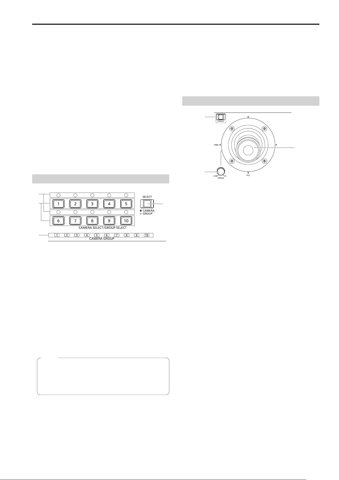
Camera selection section
Mode selection button [SELECT]
7
Each press of this switches the button indicator between on and off
in the order of on → off → on, and so on, and switches the operation
mode of the camera selection buttons (8).
Button indicator on : Camera selection mode
Button indicator off : Camera group selection mode
Camera selection buttons
8
[CAMERA SELECT/GROUP SELECT 1 to 10]
Use these to select the remote camera or camera group to control
from the unit.
Pressing any of [1] to [10] in camera selection mode switches to the
corresponding remote camera.
Pressing any of [1] to [10] in camera group selection mode switches
to the corresponding camera group and turns on the corresponding
camera group indicator (9).
Note
If a camera selection button is pressed to switch the remote
camera that the unit controls while the OSD menu of a remote
camera is displayed, the CAMERA OSD button indicator (4)
turns off and the OSD menu of the remote camera originally
selected disappears.
Camera group indicators [CAMERA GROUP 1 to 10]
9
The indicator for the selected camera group number is on.
Camera status indicators [1] to [10]
:
These indicate the statuses of the remote cameras assigned to [1] to
[10].
⇒ “Selecting a remote camera” (page 38)
Pan and tilt section
PAN/TILT lever
Use this to control the direction in which the currently selected remote
camera points.
The movement speed differs depending on the angle to which the
PAN/TILT lever is moved.
Moved left or right : The camera points to the left or right.
Moved toward you or away from you:
When the function for linking with a switcher is enabled, you can
use the PAN/TILT lever to control switcher parameters.
⇒ “Setting linking with a switcher” in Operations and Settings
(page 31)
Setting [REVERSE] in PAN DIRECTION menu [26] and TILT
DIRECTION menu [27] changes the direction the camera moves in
relation to the direction that the lever is moved.
PAN/TILT SPEED dial [SPEED]
<
Use this to adjust the operation speed variation amount for PAN/TILT
lever operation.
Turned clockwise : Operation is at a higher speed (HI)
Turned counterclockwise : Operation is at a lower speed (LOW)
PAN/TILT ENABLE button [ENABLE]
=
Use this to enable PAN/TILT lever operation.
Button indicator on or blinking: PAN/TILT lever operation is
Button indicator off : PAN/TILT lever operation is
The PAN/TILT ENABLE button indicator is on while the PAN/TILT
lever is being used to control the direction in which the remote
camera points.
The PAN/TILT ENABLE button indicator is blinking while the PAN/
TILT lever is being used to control the switcher parameters.
When the [7. P/T/Z CONTROL] item in SW FUNCTION menu [42]
is set to [Button Select], pressing the PAN/TILT ENABLE button
switches the control application of the PAN/TILT lever.
⇒ “Setting linking with a switcher” in Operations and Settings
(page 31)
The camera points up or down.
enabled.
disabled.
13

Parts and their functions (continued)
Focus, zoom and iris section
FOCUS dial [FOCUS]
>
Use this to manually control the focus.
During auto focusing (when the auto focus button [] indicator is on),
operation is disabled.
Turned clockwise : The focus moves to the far end.
Turned counterclockwise: The focus moves to the near end.
Setting “REVERSE” in FOCUS DIRECTION menu [29] changes
the direction the focus moves in relation to the direction that the
FOCUS dial is turned.
Auto focus button [AUTO]
Use this to set focus control to [Auto (auto focus)].
During auto focusing, operation of the FOCUS dial (>) and onetouch auto focus button () is disabled.
Button indicator on : Auto focus
Button indicator off : Manual focus
When a lens equipped with an extender function is used for the
remote camera, each press of this button switches the extender
function on or off.
Button indicator on : The extender function is enabled.
Button indicator off : The extender function is disabled.
(For details on how to connect the lens control cables to the pan-tilt
head, refer to the operating instructions of the pan-tilt head.)
Button operation is disabled if the remote camera has no auto
focus function and lens extender function.
One-touch auto focus button [OTAF]
When this button is pressed during manual focusing (when the auto
focus button [] indicator is off), the button indicator turns on for a
brief moment and the auto focusing operation is performed to bring
the subject into focus.
Button operation is disabled if the remote camera has no auto
focus function.
FOCUS SPEED dial [SPEED]
A
Use this to adjust the operation variation amount for FOCUS dial (>)
operation.
Turned clockwise : Operation is at a higher speed (HI)
Turned counterclockwise: Operation is at a lower speed (LOW)
ZOOM button [ZOOM]
B
Use this to adjust the lens zoom.
The zooming speed changes depending on the extent to which the
button is pressed.
When the TELE side is pressed : Telephoto setting
When the WIDE side is pressed : Wide-angle setting
When the function for linking with a switcher is enabled, you can press
the ZOOM button to control switcher parameters.
⇒ “Setting linking with a switcher” in Operations and Settings
(page 31)
Setting [REVERSE] in ZOOM DIRECTION menu [28] changes the
direction the lens zoom moves in relation to the direction that the
ZOOM button is moved.
ZOOM SPEED dial [SPEED]
X
Use this to adjust the operation variation amount for ZOOM button
(B) operation.
Turned clockwise : Operation is at a higher speed (HI)
Turned counterclockwise: Operation is at a lower speed (LOW)
IRIS dial [IRIS]
During manual iris (when the auto iris button [] indicator is off), use
this to manually control the lens iris.
During auto iris (when the auto iris button () indicator is on), use
this to adjust the convergence level of the auto iris of the remote
camera.
Turned clockwise : The lens iris opens.
Turned counterclockwise: The lens iris closes.
Auto iris button [AUTO]
Use this to set lens iris control to [Auto (auto iris)].
Button indicator on : Auto iris
Button indicator off : Manual iris
When AW-HE50 or AW-HE60 is being controlled, Contrast Mode
switches to “Auto” or “Manual” in conjunction with the selection
of auto iris or manual iris. Also, if you set the shooting mode to
“FullAuto”, the lens iris is fixed to auto iris and button operation is
disabled.
FOCUS/ZOOM/IRIS ENABLE button [ENABLE]
Use this to enable or disable operation of the FOCUS dial (>),
ZOOM button (B) and IRIS dial ().
Button indicator on or blinking:
Button indicator off : Operation of the FOCUS dial, ZOOM button
The FOCUS/ZOOM/IRIS button indicator is on while the ZOOM
button is being used to control the lens zoom.
The FOCUS/ZOOM/IRIS ENABLE button indicator is blinking while
the ZOOM button is being used to control the switcher parameters.
When the [7. P/T/Z CONTROL] item in SW FUNCTION menu
[42] is set to [Button Select], pressing the FOCUS/ZOOM/IRIS
ENABLE button switches the control application of the ZOOM
button.
⇒ “Setting linking with a switcher” in Operations and Settings
(page 31)
Operation of the FOCUS dial, ZOOM button
and IRIS dial is enabled.
and IRIS dial is disabled.
14
Loading...