


Operating Instructions
Excerpted Version
Installation Instructions provided
4K Integrated Camera
Model No. AW UE150WP
Model No. AW UE150KP
Model No. AW UE150WE
Model No. AW UE150KE
ENGLISH
Excerpted Version
FRANÇAIS
ESPAÑOL
DEUTSCH
ITALIANO
PУССКИЙ
Before installing and using this product, be sure to read “Read this first!” (pages 4, 25 to 27). This manual contains information excerpted from the Operating Instructions.
For more information, please visit the Panasonic website (https://pro-av.panasonic.net/manual/en/index.html), and refer to the Operating Instructions.
Avant d’installer et d’utiliser cet appareil, s’assurer de lire la section « Lire ces informations en premier ! » (pages 4, 28 à 30).
Pour de plus amples informations, visiter le site Web de Panasonic (https://pro-av.panasonic.net/manual/en/index. html) et consulter le mode d’emploi et les instructions d’installation.
Antes de instalar y usar este producto, asegúrese de leer “Lea esto primero!” (páginas 4, 31 a 33).
Si desea obtener más información, visite el sitio web de Panasonic (https://pro-av.panasonic.net/manual/en/index. html) y consulte las instrucciones de funcionamiento y las instrucciones de instalación.
Bitte lesen Sie sorgfältig „Bitte lesen Sie zuerst diesen Hinweis!“ vor der Installation und Nutzung dieses Produkts. (Seiten 5, 34 bis 35). Weitere Informationen finden Sie auf der Panasonic-Webseite (https://pro-av.panasonic.net/manual/en/index. html), in der Bedienungsanleitung und in der Installationsanleitung.
Prima di installare e utilizzare il prodotto, assicurarsi di leggere “Leggere prima quanto segue!” (pagine 5, 36 a 37).
Per maggiori informazioni, visitare il sito Web Panasonic (https://pro-av.panasonic.net/manual/en/index.html) e fare riferimento alle istruzioni per l’uso e alle istruzioni per l’installazione.
Перед установкой и использованием данного изделия ознакомьтесь с информацией в разделе «Прочитайте нижеследующее до начала эксплуатации!» (стр. 5, 38 до 39).
Для получения дополнительной информации посетите веб-сайт Panasonic (https://pro-av.panasonic.net/ manual/en/index.html) и обратитесь к инструкции по эксплуатации и инструкции по установке.
Before operating this product, please read the instructions carefully and save this manual for future use.
PJ |
|
EJ |
|
|
SS1018YM0 -FJ |
ENGLISH |
|||
|
||||
Printed in Japan |
DVQX1709ZA |
|||
български
Hrvatski
Čeština
Dansk
Nederlands
Eesti
Suomi
Ελληνικά
Magyar
Посетете следния уебсайт относно информация за безопасността и важни уведомления за продукта.
Za sigurnosne informacije i važne obavijesti o proizvodu posjetite sljedeću internetsku stranicu.
Na následujícím webu najdete bezpečnostní informace a důležité poznámky k tomuto produktu.
Besøg følgende webside for sikkerhedsinformation og vigtige bemærkninger vedrørende produktet.
Ga naar de volgende website voor veiligheidsinformatie en belangrijke meldingen over het product.
Toodet puudutava ohutusteabe ja oluliste märkuste saamiseks külastage järgmist veebilehte.
Käy seuraavalla verkkosivulla saadaksesi turvallisuustietoja ja tärkeitä tietoja liittyen laitteeseen.
Για πληροφορίες σχετικά με θέματα ασφάλειας και σημαντικές ειδοποιήσεις που αφορούν το προϊόν σας, επισκεφτείτε τον ιστότοπο που ακολουθεί.
A termékkel kapcsolatos biztonsági információkért és fontos értesítésekért látogasson el az alábbi weboldalra.
Latviešu
Lietuvių
Polski
Português
Română
Slovensky
Slovenščina
Svenska
Lai iegūtu informāciju par drošību un skatītu svarīgus paziņojumus par šo produktu, apmeklējiet tālāk norādīto tīmekļa vietni.
Jei reikia saugos informacijos ir svarbių pranešimų apie gaminį, apsilankykite toliau nurodytoje svetainėje.
Informacje o bezpieczeństwie i ważne informacje o produkcie znajdują się w poniższej witrynie internetowej.
Consulte o seguinte website para as informações de segurança e importantes notificações sobre o produto.
Vizitați următoarea pagină web pentru informaţii de securitate și notificări importante cu privire la produs.
Pre bezpečnostné informácie a dôležité oznámenia súvisiace s produktom navštívte túto webovú stránku.
Za varnostne informacije in pomembna obvestila v zvezi z izdelkom obiščite naslednje spletno mesto.
Besök följande webbplats för säkerhetsinformation och viktiga meddelanden om produkten.
https://pro-av.panasonic.net/manual/en/index.html
Trademarks and registered trademarks
•Microsoft®, Windows®, Windows® 7, Windows® 10, Microsoft Edge, Internet Explorer®, ActiveX® and DirectX® are either registered trademarks or trademarks of Microsoft Corporation in the United States and other countries.
•Apple, Mac, Mac OS, OS X, iPhone, iPad, and Safari are registered trademarks of Apple Inc., in the United States and other countries.
•Android™ and Chrome™ browser are trademarks of Google LLC.
•Intel® and Intel® Core™ are trademarks or registered trademarks of Intel Corporation in the United States and other countries.
•Adobe® and Reader® are either registered trademarks or trademarks of Adobe Systems Incorporated in the United States and/or other countries.
•The terms HDMI and HDMI High-Definition Multimedia Interface, and the HDMI Logo are trademarks or registered trademarks of HDMI Licensing Administrator, Inc. in the United States and other countries.
•NDI® is a registered trademark of NewTek, Inc.
•Other names of companies and products contained in these
Operating Instructions may be trademarks or registered trademarks of their respective owners.
About copyright and licence
Distributing, copying, disassembling, reverse compiling, reverse engineering, and also exporting in violation of export laws of the software provided with this unit are expressly prohibited.
Abbreviations
The following abbreviations are used in this manual.
•Microsoft® Windows® 7 Professional SP1 32/64-bit is abbreviated to “Windows 7”.
•Windows® Internet Explorer® 11 32/64 bit is abbreviated to “Internet Explorer”.
For the purposes of this manual, the model numbers of the units are given as listed in the table below.
Model number of unit |
Model number given in |
|
manual |
||
|
AW UE150WP
AW UE150KP
AW UE150WE
AW UE150
AW UE150KE
AW-RP150G AW-RP150
Illustrations and screen displays featured in the manual
•What is shown in the manual’s illustrations and screen displays may differ from how it is actually appears.
•Functions which can be used by Windows Internet Explorer 11
only are indicated using the |
mark. |
•The screenshots are used in accordance with the guidelines of
Microsoft Corporation.
2

Contents
Installation Instructions |
|
Read this first!........................................................................................ |
4 |
Lire ces informations en premier !....................................................... |
4 |
Lea esto primero!................................................................................... |
4 |
Bitte lesen Sie zuerst diesen Hinweis!................................................. |
5 |
Leggere prima quanto segue!............................................................... |
5 |
Прочитайте нижеследующее до начала эксплуатации!................ |
5 |
Installation precautions......................................................................... |
6 |
Before installation.................................................................................. |
8 |
IR ID switch settings............................................................................. |
8 |
Service switch settings......................................................................... |
8 |
How to install and connect the unit...................................................... |
9 |
When using the WV Q105A (optional accessory).............................. |
13 |
Removing the camera.......................................................................... |
14 |
Stand-alone installation |
|
(when the mount bracket is going to be used)............................. |
15 |
Stand-alone installation |
|
(when the mount bracket is not going to be used)....................... |
17 |
When installing the unit on a desktop................................................. |
17 |
When mounting the unit on a tripod.................................................... |
17 |
Connections......................................................................................... |
18 |
Connecting an NDI|HX compatible switcher....................................... |
18 |
Connections with a controller (AW-RP150)........................................ |
19 |
System example 1 (Serial control)...................................................... |
20 |
System example 2 (IP control)........................................................... |
21 |
System example 3 (IP image transmission, PoE++).......................... |
22 |
Appearance........................................................................................... |
23 |
Operating Instructions |
|
Read this first! ..................................................................................... |
24 |
Note on grounding.............................................................................. |
24 |
Read this first! (For AW UE150WP, AW UE150KP)........................... |
25 |
Read this first! (For AW UE150WE, AW UE150KE)........................... |
26 |
Lire ces informations en premier ! |
|
(Pour AW UE150WP, AW UE150KP).............................................. |
28 |
Lire ces informations en premier ! |
|
(Pour AW UE150WE, AW UE150KE).............................................. |
29 |
Lea esto primero! (Para AW UE150WP, AW UE150KP).................... |
31 |
Lea esto primero! (Para AW UE150WE, AW UE150KE).................... |
32 |
Bitte lesen Sie zuerst diesen Hinweis! |
|
(Für AW UE150WE, AW UE150KE)................................................. |
34 |
Leggere prima quanto segue! |
|
(Per AW UE150WE, AW UE150KE)................................................. |
36 |
Прочитайте нижеследующее до начала эксплуатации! |
|
(Для AW UE150WE, AW UE150KE)................................................ |
38 |
Before use............................................................................................. |
40 |
Overview............................................................................................. |
40 |
Computer requirements...................................................................... |
40 |
Disclaimer of warranty........................................................................ |
41 |
Network security................................................................................. |
41 |
Features................................................................................................ |
42 |
Accessories.......................................................................................... |
43 |
Optional accessories........................................................................... |
43 |
Operating precautions......................................................................... |
44 |
Wireless remote control (optional accessory).................................. |
46 |
Parts and their functions..................................................................... |
47 |
Camera unit........................................................................................ |
47 |
Wireless remote control: AW RM50G (not supplied).......................... |
54 |
Setting the remote control IDs............................................................ |
56 |
Network settings.................................................................................. |
57 |
Use the Easy IP Setup Software to establish the unit’s settings........ |
57 |
Setting the initial account.................................................................... |
58 |
Installing the plug-in viewer software.................................................. |
58 |
How to turn the power on and off....................................................... |
59 |
Turning the power on.......................................................................... |
59 |
Turning the power off.......................................................................... |
59 |
Troubleshooting................................................................................... |
60 |
Specifications....................................................................................... |
69 |
Index...................................................................................................... |
70 |
3

Installation Instructions
Read this first!
ENGLISH
|
|
|
|
|
|
|
|
|
|
|
|
|
|
|
|
|
|
|
|
WARNING: |
|
CAUTION: |
|
|
||
|
|
To prevent injury, this apparatus must be securely attached to |
|
This camera intended for use only with the Mount Bracket |
|
|
||
|
|
the floor/wall in accordance with the installation instructions. |
|
enclosed with the unit and Panasonic Direct Ceiling Mount |
|
|
||
|
|
|
|
|
|
Bracket, WV-Q105A. |
|
|
|
|
|
|
|
|
|||
|
|
|
|
|
|
Use with other apparatus is capable of resulting in instability |
|
|
|
|
WARNING: |
|
causing possible injury. |
|
|
||
|
|
|
|
|
|
|||
|
|
Installation should only be performed by qualified installation |
|
|
|
|
||
|
|
personnel. |
|
|
|
|
||
|
|
Improper installation may result in the entire apparatus falling |
|
|
|
|
||
|
|
down and causing injury. |
|
|
|
|
||
|
|
|
|
|
|
|
|
|
|
|
|
|
|
|
|
|
|
|
|
|
|
|
|
|
|
|
|
|
|
|
indicates safety information. |
|
|
|
|
|
|
|
|
|
|
|
|
|
|
|
|
|
|
|
|
|
|
Lire ces informations en premier ! |
|
|
|
||||||
|
|
FRANÇAIS |
|||||||
|
|
|
|
|
|
|
|
|
|
|
|
|
|
|
|
|
|
|
|
|
|
|
|
|
|
|
|
|
|
|
|
AVERTISSEMENT: |
|
ATTENTION: |
|
|
|||
|
|
Pour éviter tout risque de blessures, l’appareil doit être |
|
Cette caméra est conçue pour être utilisée uniquement avec la |
|
|
|||
|
|
solidement fixé au plancher/mur conformément aux instructions |
|
potence de fixation fournie avec l’appareil ou avec la potence de |
|
|
|||
|
|
d’installation. |
|
fixation directe au plafond Panasonic WV-Q105A. |
|
|
|||
|
|
|
|
|
|
L’utilisation de tout autre dispositif risque de se traduire par une |
|
|
|
|
|
|
|
|
|
||||
|
|
|
|
|
|
instabilité et être cause de blessures à des personnes. |
|
|
|
|
|
AVERTISSEMENT: |
|
|
|
|
|
||
|
|
|
|
|
|
|
|||
|
|
L’installation ne doit être effectuée que par du personnel |
|
|
|
|
|
||
|
|
d’installation qualifié. |
|
|
|
|
|
||
|
|
Une mauvaise installation peut avoir pour conséquence la chute |
|
|
|
|
|
||
|
|
de l’appareil et provoquer des blessures. |
|
|
|
|
|
||
|
|
|
|
|
|
|
|
|
|
|
|
|
|
|
|
|
|
|
|
|
|
|
|
|
|
|
|
|
|
|
|
|
|
Informations concernant la sécurité. |
|
|
|
|
|
|
|
|
|
|
|
|
|
|
|
|
|
|
|
|
|
|
|
|
|
Lea esto primero! |
|
|
|
||||||
|
|
ESPAÑOL |
|||||||
|
|
|
|
|
|
|
|
|
|
|
|
|
|
|
|
|
|||
|
|
|
|
|
|
|
|||
|
|
ADVERTENCIA: |
|
PRECAUCIÓN: |
|
|
|||
|
|
Para evitar heridas, este aparato debe estar firmemente |
|
Esta cámara ha sido diseñada para ser utilizada solamente |
|
|
|||
|
|
instalado al piso/pared de acuerdo con las instrucciones de |
|
con la ménsula de montaje suministrada con la unidad y con la |
|
|
|||
|
|
instalación. |
|
ménsula de montaje directo en el techo de Panasonic modelo |
|
|
|||
|
|
|
|
|
|
WV-Q105A. |
|
|
|
|
|
|
|
|
|
|
|||
|
|
|
|
|
|
La utilización con otros aparatos puede causar inestabilidad y |
|
|
|
|
|
ADVERTENCIA: |
|
posibles lesiones. |
|
|
|||
|
|
|
|
|
|
|
|||
|
|
La instalación solamente debe llevarla a cabo personal |
|
|
|
|
|
||
|
|
cualificado. |
|
|
|
|
|
||
|
|
Una instalación incorrecta podría provocar la caída del |
|
|
|
|
|
||
|
|
dispositivo y causar lesiones. |
|
|
|
|
|
||
|
|
|
|
|
|
|
|
|
|
|
|
|
|
|
|
|
|
|
|
|
|
|
|
|
|
|
|
|
|
|
|
|
|
indica información de seguridad. |
|
|
|
|
|
|
|
|
|
|
|
|
|
|
|
|
|
|
|
|
|
|
|
|
|
4

Bitte lesen Sie zuerst diesen Hinweis!
Installation Instructions
DEUTSCH
|
|
|
|
|
|
|
|
|
|
|
|
|
|
|
|
|
|
|
|
WARNUNG: |
|
VORSICHT: |
|
|
||
|
|
Um Verletzungen zu verhüten, muss dieser Apparat gemäß |
|
Diese Kamera ist nur für den Einsatz mit der mitgelieferten |
|
|
||
|
|
der Installationsanleitung sicher am Boden bzw. an der Wand |
|
Montagehalterung und der Panasonic Decken- |
|
|
||
|
|
befestigt werden. |
|
Direktmontagehalterung WV-Q105A vorgesehen. |
|
|
||
|
|
|
|
|
|
Wird die Kamera mit anderen Apparaten verwendet, kann es zu |
|
|
|
|
|
|
|
|
|||
|
|
|
|
|
|
Instabilität kommen, die Verletzungen verursachen kann. |
|
|
|
|
WARNUNG: |
|
|
|
|
||
|
|
|
|
|
|
|||
|
|
Die Installation darf nur durch qualifiziertes Personal ausgeführt |
|
|
|
|
||
|
|
werden. |
|
|
|
|
||
|
|
Fehlerhafte Installation kann zum Herunterfallen des Gerätes |
|
|
|
|
||
|
|
und zu Verletzungen führen. |
|
|
|
|
||
|
|
|
|
|
|
|
|
|
|
|
|
|
|
|
|
|
|
|
|
|
|
|
|
|
|
|
|
|
|
|
ist die Sicherheitsinformation. |
|
|
|
|
|
|
|
|
|
|
|
|
|
|
|
|
|
|
|
|
|
|
Leggere prima quanto segue!
ITALIANO
|
|
|
|
|
|
|
|
|
|
|
|
|
|
|
|
|
|
|
|
AVVISO: |
|
PRECAUZIONE: |
|
|
||
|
|
Per prevenire ferite, questo apparecchio deve essere montato |
|
La videocamera deve essere utilizzata esclusivamente con la |
|
|
||
|
|
saldamente al pavimento/muro in conformità alle istruzioni di |
|
staffa di montaggio in dotazione con l’unità e con la staffa per |
|
|
||
|
|
installazione. |
|
montaggio diretto a soffitto WV-Q105A. |
|
|
||
|
|
|
|
|
|
L’uso con altri apparecchi potrebbe causare instabilità ed |
|
|
|
|
|
|
|
|
|||
|
|
|
|
|
|
eventuali infortuni. |
|
|
|
|
AVVISO: |
|
|
|
|
||
|
|
|
|
|
|
|||
|
|
L’installazione deve essere realizzata unicamente da tecnici |
|
|
|
|
||
|
|
qualificati. |
|
|
|
|
||
|
|
Un’installazione incorretta può risultare nella caduta |
|
|
|
|
||
|
|
dell’apparecchio con conseguenti danni alle persone. |
|
|
|
|
||
|
|
|
|
|
|
|
|
|
|
|
|
|
|
|
|
|
|
|
|
|
|
|
|
|
|
|
|
|
|
|
sono le informazioni sulla sicurezza. |
|
|
|
|
|
|
|
|
|
|
|
|
|
|
|
|
|
|
|
|
|
|
Прочитайте нижеследующее до начала эксплуатации! |
|
||||||||
РУССКИЙ |
|||||||||
|
|
|
|
|
|
|
|
|
|
|
|
|
|
|
|
|
|
|
|
|
|
|
|
|
|
|
|
|
|
|
|
ОСТОРОЖНО: |
|
ВНИМАНИЕ: |
|
|
|
||
|
|
Во избежание повреждения данный прибор должен |
|
Данная камера предназначена для использования только с |
|
|
|||
|
|
быть надежно закреплен на полу/стене в соответствии с |
|
монтажным кронштейном, поставляемым с устройством, и |
|
|
|||
|
|
инструкцией по установке. |
|
монтажным кронштейном Panasonic для непосредственного |
|
|
|||
|
|
|
|
|
|
крепления к потолку WV-Q105A. |
|
|
|
|
|
|
|
|
|
|
|
||
|
|
|
|
|
|
Использование с другим аппаратом может привести к |
|
|
|
|
|
ОСТОРОЖНО: |
|
нарушению устойчивости и возможной травме. |
|
|
|
||
|
|
|
|
|
|
|
|||
|
|
Установка должна выполняться только квалифицированным |
|
|
|
|
|
||
|
|
специалистом по установке. |
|
|
|
|
|
||
|
|
Ненадлежащая установка может привести к падению всего |
|
|
|
|
|
||
|
|
аппарата и получению травмы. |
|
|
|
|
|
||
|
|
|
|
|
|
|
|
|
|
|
|
|
|
|
|
|
|
|
|
|
|
|
|
|
|
|
|
|
|
|
|
|
|
Данный знак обозначает информацию, относящуюся к технике безопасности. |
|
|
|
||
|
|
|
|
|
|
|
|||
|
|
|
|
|
|
|
|
|
|
5

Installation Instructions
Installation precautions
Panasonic does not accept any responsibility for accident or damage during installation if procedure in this manual is not followed.
To installation personnel
Read the “Installation Instructions” thoroughly and then perform the operation correctly and safely.
Also, always read the “Read this first!” (→ page 4) of this manual as they contain important information.
After the installation, give the “Installation Instructions” to the customer to save for future use.
Ensure that the installation work complies with the technical standards governing electrical equipment.
This unit is for indoor use only.
It cannot be used outdoors.
Avoid installation in a location where the unit will be exposed to direct sunlight for extended periods or near a cooling or heating appliance.
Otherwise, deformation, discoloration, malfunctioning and/or problems in operation may result. Operate the unit where it will not be splashed or sprayed by water.
Use the unit with an installation where the unit is suspended from an overhead surface or with a stand alone installation.
Do not use the unit on its side or tilted at an angle.
<NOTE>
•Be absolutely sure to use the four bracket mounting screws (M4) for mounting the mount bracket. These are supplied with the unit.
Do not use wood screws, nails, etc.
In the case of a concrete ceiling, secure the unit using anchor bolts
(for M4) or AY plug bolts (for M4).
Recommended clamping torque M4 : 1.47 N · m {15 kgf · cm}
•The withdrawal strength of the mounting location for each screw must be at least 461 N {47 kgf}.
•When mounting the unit on a ceiling made of plasterboard, for instance, if it is not strong enough to support its weight, either reinforce the ceiling adequately or use the WV Q105A direct ceiling mount bracket, which is sold separately.
•When using a mount bracket which is sold separately, read the handling instructions.
•Do not hold the camera head while undertaking the installation work. Doing so may cause malfunctioning.
OK NG OK NG
Desktop installation |
Hanging installation |
Concerning the installation location
Install the unit in a stable location which will not be susceptible to shaking. If the unit is installed in a location which is susceptible to shaking, this will cause the unit’s images to shake in turn.
Install the unit after conferring in detail with your dealer.
Install the unit on a ceiling that is strong enough (such as a concrete ceiling).
If the unit is to be installed on a ceiling which is not strong enough, reinforce the ceiling sufficiently first.
Do not install or use the unit in the following kinds of locations.
•On walls (where the unit would be installed sideways)
•In locations (including places such as under the eaves of a building) where the unit would be directly exposed to rain or water
•In locations such as kitchens where there are high concentrations of steam and grease
•In outdoor locations or hot places where the temperature will exceed 40 °C (104 °F)
•In cold locations where the temperature will drop below 0 °C (32 °F)
•In locations where the humidity will exceed 85%
•In locations where chemicals are used such as near swimming pools
•At sea, in coastal areas or in locations where corrosive gases are emitted
•In locations where radiation, X-rays, or strong radio waves or magnetic fields are generated
•In locations where the unit would be subject to a great deal of vibration such as on board a vehicle or ship (this unit is not designed to be used in vehicles)
•In locations where the temperature is subject to sudden changes such as near the air outlet of an air conditioner or near a door which allows the outside air to come in
What to avoid to ensure that the unit will perform stably over a prolonged period
•Using the unit for a prolonged period in a location with high temperature and humidity levels will cause its parts to deteriorate and shorten its service life.
•Ensure that a cooling unit or heating unit will not blow any air directly toward the installation location.
Be absolutely sure to use the supplied brackets and screws to install the camera.
•Do not mount the unit by employing any methods other than those specified.
•Do not remodel the mounting bracket or mounting screws provided with the unit.
AW UE150 |
|
|
|
|
Mounting conditions |
|
|
|
|
main unit |
|
Applicable mount bracket |
|
|
Mounting onto the ceiling |
||||
Mass |
Model No. |
|
Mass |
Mounting |
|
Recommended |
|
No. of |
Minimum withdrawal strength |
|
|
screws |
|
screws |
(per screw) |
||||
|
|
|
|
|
|
|
|||
|
Direct mount |
|
Approx. |
|
|
M4 screws |
|
|
461 N {47 kgf} |
Approx. |
(supplied |
|
0.35 kg |
Hanging/Desktop |
|
4 |
• Ensure that the mounting strength |
||
|
(supplied accessory) |
|
|||||||
4.2 kg (9.24 lb) |
accessory) |
|
(0.77 lb) |
|
|
|
|
can support a weight that is at least |
|
|
|
|
|
|
|
||||
(excluding mount |
WV Q105A |
|
Approx. |
|
|
M4 screws |
|
|
five times the total mass of the |
bracket) |
(optional |
|
0.15 kg |
For ceiling |
|
(supplied with the |
|
4 |
equipment, including the camera’s |
|
accessory) |
|
(0.33 lb) |
|
|
WV Q105A) |
|
|
main unit. |
6

Installation Instructions
Installation precautions (continued)
Before installation, always disconnect the DC connector
When installing, always use the supplied components. Do not disassemble or modify the wall mount adaptor.
Tightening up the mounting screws
•Tighten up the screws and bolts securely to the degree that is appropriate for each of the materials used in the mounting location and structures.
•After tightening up the screws and bolts, check that there is no unsteadiness and that the parts have been tightened securely.
•Use the specified tools and tighten the screws firmly.
•Tighten up the screws using the specified torque driver. Do not use electrical drivers or impact drivers.
When the unit is no longer going to be used, do not leave it lying around, but be absolutely sure to dispose of it properly.
For details on how to remove the unit, refer to “Removing the camera” (→ page 14).
Power switch
This unit does not have a power switch. When the power is supplied, the pan, tilt, zoom and focusing operations are
performed.*1 Before proceeding with maintenance, be absolutely sure to disconnect the power plug from the power outlet.
*1 • Under factory default conditions, the unit will be in Standby mode when power is supplied for the first time. (Status display lamp: Lit orange)
•When the power supply is cut off while the unit is in Standby mode, the unit will be in Standby mode the next time power is supplied. (Status display lamp: Lit orange)
•When the power supply is cut off while the unit is in Power ON mode, the unit will be in Power ON mode the next time power
is supplied. (Status display lamp: Lit green)
(For details, refer to “How to turn the power on and off” (→ page 59).)
Grounding
Before operating the unit, check that SIGNAL GND has been securely grounded.
When installing, transferring or disposing of the unit, be absolutely sure to hold it by its pedestal area.
Problems may result if the camera head is held or rotated.
Do not attach a filter, hood, extender or other parts to the unit.
Install the external DC power supply near the main power outlet, and position it in such a way that its power plug can be plugged into and unplugged from the outlet easily.
When connecting the external DC power supply to a power outlet on the ceiling or on any other surface where dust may collect, wipe off the dust on the power plug at periodic intervals as an anti tracking measure.
If there is a possibility of noise interference
Either wire the cables so that the power cable (ceiling light cord) of AC 100 V*2 (AC 220 V*3 ) or more, and the signal cable are placed at least 1 meter (3.3 ft) apart.
Alternatively run each cable through its own metal conduit. (The metal conduits must be grounded.)
*2 For AW UE150WP, AW UE150KP
*3 For AW UE150WE, AW UE150KE
Radio signal interference
If the unit is positioned near a TV or radio transmitting antenna or a strong electrical field or magnetic field (such as that generated by a motor, transformer or power lines), its images may be distorted and/ or the images may be affected by noise.
When connecting the cables, ensure that the connector areas will not be subject to any load.
Doing so may cause malfunctioning.
Allowing the generated heat to escape
This unit allows the heat generated inside to escape from its surfaces.
Do not install the unit in a location where it will be surrounded by walls or other surfaces and where heat will be trapped.
In addition, the heat is dissipated to the bottom panel which will warm up over time: This is normal and not indicative of any trouble.
PoE++ power supplies
Use a PoE++ [IEEE802.3bt Draft ver.2.0 standard (LLDP not supported)] compatible hub or power supply device.
Network settings
The network function of this unit does not work unless an initial account is set up (except when using the Easy IP Setup Software (→ page 57)). A personal computer is required to set up an initial account. (→ page 58)
<NOTE>
•Network connection with AW RP150 also requires setup of an initial account. When an initial account is not set up, AW RP150 can detect but cannot control this unit.
7

Installation Instructions
Before installation
Be sure to configure the switches on the connector panel and bottom of the unit before installing it. Configuring the switches after the unit is installed may prove difficult.
IR ID switch settings
The IR ID switches are located on the connector panel of the unit.
LAN |
SERVICE |
|
LINK |
ACT |
RS-422 |
|
|
|
|
3G SDI OUT G/L IN |
12 V |
IN |
|
|
|
|
|
OPTICAL |
|
|
IR ID |
MONI OUT 12G SDI OUT |
|
|
AUDIO IN |
|
IR ID switch
|
|
CAM1 |
|
|
CAM2 |
|
|
CAM3 |
|
|
CAM4 |
||||||||||||||||
|
|
|
|
|
|
|
|
|
|
|
|
|
|
|
|
|
|
|
|
|
|
|
|
|
|
|
|
|
|
|
|
|
|
|
|
|
|
|
|
|
|
|
|
|
|
|
|
|
|
|
|
|
|
|
|
|
|
|
|
|
|
|
|
|
|
|
|
|
|
|
|
|
|
|
|
|
|
|
|
|
|
|
|
|
|
|
|
|
|
|
|
|
|
|
|
|
|
|
|
|
|
|
|
|
|
|
|
|
|
|
|
|
|
|
|
|
|
|
|
|
|
|
|
|
|
|
|
|
|
|
|
|
|
|
|
|
|
|
|
|
|
|
|
|
|
|
|
|
|
|
|
|
|
|
|
|
|
|
|
|
|
|
|
|
|
|
|
|
|
|
|
|
|
|
|
|
|
|
|
|
|
|
|
|
|
|
|
|
|
|
|
|
|
|
|
|
|
|
|
|
|
|
|
|
|
|
|
|
|
|
|
|
|
|
|
|
|
|
|
|
|
|
|
These are used to select the ID of the wireless remote control (optional accessory). (→ page 56)
The IR ID switch settings “CAM1” to “CAM4” correspond to the <CAM1> to <CAM4> buttons on the wireless remote control.
Service switch settings
The service switches are located on the connector panel of the unit. Perform switch settings before turning the unit on.
Service switch
SW1 SW2 SW3 SW4
ON
OFF
LAN |
SERVICE |
LINK ACT |
RS-422 |
3G SDI OUT G/L IN
12 V IN |
|
|
OPTICAL |
IR ID |
MONI OUT 12G SDI OUT |
AUDIO IN |
|
Function |
Factory settings |
|
SW1 |
Switches for initialization |
|
|
|
(Refer to the explanations in “Initialization 1” |
OFF |
|
|
and “Initialization 2”) |
|
|
SW2 |
Always leave at OFF (used for factory |
OFF |
|
SW3 |
OFF |
||
adjustments) |
|||
SW4 |
OFF |
||
|
Initialization 1
•Reset the user authentication settings and host authentication settings for network connection.
(This will delete all the registered user information (IDs/passwords) and host information (IP addresses).)
•With the IR ID switches and service switches set as shown below, turn
on the power of the unit.
SW1 SW2 SW3 SW4
ON
OFF
<NOTE>
•When initialization is complete, the status display lamp on the front of the unit blinks green. Restart the unit to confirm the initialization.
Initialization 2
•The unit is reset to the state it was in at the time of purchase. (All camera menu setting values and network setting values are reset.)
•With the IR ID switches and service switches set as shown below, turn
on the power of the unit.
SW1 SW2 SW3 SW4
ON
OFF
<NOTE>
•When initialization is complete, the status display lamp on the front of the unit blinks green. Restart the unit to confirm the initialization.
8

Installation Instructions
How to install and connect the unit
Be absolutely sure to read through the “Read this first!” (→ page 4) and “Installation precautions” (→ pages 6 to 7).
The procedure given here is for the kind of installation where the unit is suspended from an overhead surface, but the same steps are followed for a stand-alone installation.
If the ceiling panel is not strong enough to bear the unit’s weight, use the kind of mount bracket that is supported by anchor bolts between the concrete ceiling and ceiling panel. The unit supports the WV Q105A direct ceiling mount bracket which is used solely for combination cameras. Use this bracket to install the unit. (→ page 13)
In a case like this, the holes (ø 60 mm (ø 2-3/8 inches)) for installing the direct ceiling mount bracket on the ceiling must be drilled in the ceiling panel.
It is also recommended that you provide an inspection space or opening for access purposes in the area near where the equipment is installed in order to facilitate installation and the wiring connections work.
For details on supplied accessories, refer to the page 43.
1.Check the mounting space.
•Refer to the illustration, and determine where the unit is to be installed and in which direction it should be mounted. Factor in the unit mounting area and include space for the wires extending from its rear panel.
•The asterisk () in the illustration marks the position and dimensions of the hole for mounting the mount bracket.
Through-hole for cable ø 40 (ø 1-9/16) (reference)
Unit mounting area 
Hole for mounting the main unit mounting screw
Hook for mounting the drop-prevention wire
Mount bracket
160 (6-5/16)
(Space for the wires from the rear panel)
Moving range of the camera head  (ø 246 (ø 9-11/16))
() Holes for mounting the mount |
83.5 |
bracket: ø 4.5 (ø 3/16) × 4 |
() |
Hole for checking the positioning |
() 46 |
|
|
|
(1-13/16) |
|
176 (6-15/16) |
|
180 (7-3/32) |
Unit: mm (inch)
|
|
|
|
|
|
|
19/32) or more |
for the wires) |
|
|
|
|
|
|
|
||
|
|
|
|
|
|
|
||
|
|
|
|
|
|
|
320 (12- |
(Space |
|
|
|
|
|
|
|
||
|
|
|
|
(5-11/32) |
|
|
||
|
|
|
|
|
|
|||
|
-1/4) |
|
|
|
|
|
||
|
108 (4 |
|
|
136 |
|
|
|
|
|
|
|
|
|
|
|||
|
|
|
|
|
|
|
|
|
|
|
|
|
|
|
|
|
|
|
|
|
|
|
|
(3-17/32) |
|
|
|
|
|
|
(3-15/32) |
|
|
||
|
|
|
|
88 |
|
90 |
|
|
|
|
|
|
|
|
|
|
|
|
|
|
|
|
|
|
|
|
|
|
|
|
|
|
|
|
|
Hole for installing the WV Q105A direct ceiling mount bracket (ø 60 (ø 2-3/8))
The front panel of the unit on this side.
<NOTE>
•Before proceeding to install and connect the main unit, connect the LAN cable, HDMI cable, optical fiber multi cable and coaxial cables in the space above the ceiling panel, and then pass the cables through the cable holes.
•For a power outlet which is used on the ceiling, be absolutely sure to take measures to deal with the tracking that may be caused by the accumulation of dust and other foreign matter.
9

Installation Instructions
How to install and connect the unit (continued)
2.Mount the mount bracket onto the installation surface.
•Use the bracket mounting screws (M4, bind-head: 10 mm (13/32 inches) long) supplied with the unit.
•For proper clamping torque, securely attach the screws using the specified tools.
Screw |
Clamping torque |
|
diameter |
||
|
||
M4 |
1.47 N · m {15 kgf · cm} |
Bracket mounting screws × 4 (supplied) (M4, bind-head)
<NOTE>
•Use only the screws supplied with the unit. Do not use any other screws such as wood screws, nails, etc.
3.Attach the drop-prevention wire.
•Loop the circle part of the drop-prevention wire, which has been attached to the bottom panel of the unit, around the end of the hook part of the mount bracket.
•Pull the drop-prevention wire, and check that it has been attached securely to the hook.
End of hook
Drop-prevention wire
ALoop the circle part of the dropprevention wire around the end of the hook part of the mount bracket.
BPull the wire, and check that it is securely attached to the hook.
<NOTE>
•Do not do this work while holding the camera head since doing so may result in malfunctioning of the unit.
•The drop-prevention wire is designed to be used for installation where the unit is suspended from an overhead surface so do not subject it to the weight of units other than the unit.
10
Installation Instructions
How to install and connect the unit (continued)
4.Mount the unit.
•Align the position of the hole for checking the positioning with the status display lamp.
•Align the holes on the camera main unit used to insert the bottom panel with the protrusions on the mount bracket used for inserting the camera, push the bracket and camera firmly together, and rotate the main unit by about 20 degrees in the direction of the arrow.
•Secure the mount bracket to the unit using the main unit mounting screw (M3) as supplied.
•Attach the mount bracket securely with the prescribed tool using the clamping torque below.
•Be absolutely sure to verify that none of the screws are loose.
Screw |
Clamping torque |
|
diameter |
||
|
||
M3 |
0.78 N · m {8 kgf · cm} |
Hole for checking 


 the positioning


On the mount bracket: Protrusions (×3) used for inserting the camera
On the camera main unit: Holes 


 (×3) used to insert


 the bottom panel

Status display lamp 

<NOTE>
Approx. 20°
Main unit mounting screw (M3 screw) (with flat washer, spring washer)
•Do not do this work while holding the camera head since doing so may result in malfunctioning of the unit.
•Use only the screws supplied. Do not use any other screws.
•Check that the unit has been mounted securely with no tilting or wobbling.
•The unit must be secured without fail using the main unit mounting screw before any of the cables are connected.
5.Check the mounting.
Check out the following points.
•The main unit mounting screw must be mounted securely.
•The unit must not tilt, and it must be mounted exactly.
•The unit must be securely installed.
•The unit pedestal part must not rotate even when an attempt is made to turn it.
11

Installation Instructions
How to install and connect the unit (continued)
6.Connect the rear panel connectors.
<NOTE>
•Do not connect PoE cable to the RS 422 port.
•When Optical output is to be used, connect the recommended optical fiber module. (→ page 49)
•For details on recommended products, refer to the catalog or consult your local dealer.
DC cable (External DC power supply)
 LAN cable
 HDMI cable
Optical fiber multi cable
Coaxial cable
12

Installation Instructions
How to install and connect the unit (continued)
When using the WV Q105A (optional accessory)
It is recommended that you provide an inspection opening or other such space for access purposes in the area near where the equipment is installed in order to facilitate installation and the wiring connections work.
Before mounting the mount bracket, check that the installation location is strong enough to withstand the total mass (approx. 4.7 kg (10.34 lb)) which will be exerted once the camera is mounted.
Use the mount bracket where the space between the ceiling panel and the concrete ceiling is at least 100 mm (3-15/16 inches) high. The bracket can be mounted where the thickness of the ceiling panel ranges from 5 mm (3/16 inches) to 40 mm (1-9/16 inches). The drop-prevention wire (supplied with the WV Q105A) must be used when mounting the direct ceiling mount bracket.
Concrete ceiling
Height above ceiling panel:
At least 100 mm (3-15/16 inches)
Ceiling panel (plasterboard, etc. with a thickness from 5 mm (3/16 inches) to 40 mm (1-9/16 inches))
Anchor bolts
(Withdrawal strength: 461 N {47 kgf} or more)
The anchor bolts must not protrude beneath the ceiling panel.
ø 60 mm (2-3/8 inches)
1.Refer to the Operating Instructions of the WV Q105A direct ceiling mount bracket, and attach the WV Q105A as well as the drop-prevention wire angle and drop-prevention wire supplied with the WV Q105A to the anchor bolts.
Mounting the anchor bolts and direct ceiling mount bracket ()
This job is facilitated if the direct ceiling mount bracket is loosely secured to the ceiling panel in one place, and the direct ceiling mount bracket and anchor bolts are vertically aligned before the nuts are tightened up.
2.First, remove the screws which were loosely fastened in step 1, and then align the camera mount bracket of the AW UE150 with the screw holes in the WV Q105A direct ceiling mount bracket and mount it in place.
• Use the mounting screws (the M4-L60 Phillips head screws with adhesive) supplied with the WV Q105A as the mounting screws.
Space above the ceiling
Drop-prevention wire |
|
(): Fasten here using the nut. |
angle (Supplied with |
|
Direct ceiling mount bracket WV Q105A (optional accessory) |
WV Q105A) |
Anchor bolts |
|
Drop-prevention wire |
|
Plasterboard or other ceiling panel |
|
|
|
(Supplied with WV Q105A) |
|
|
Inspection opening recommended |
|
Camera mount bracket |
• The installation and wiring connection |
|
(Supplied with AW UE150) |
work is facilitated if an inspection opening |
|
|
is provided for access purposes. |
|
|
Mounting screw × 4 |
|
|
(Supplied with WV Q105A) |
|
|
AW UE150
3. Install the AW UE150 camera by following the procedure starting with step 3 on page 10.
13

Installation Instructions
Removing the camera
1.Turn off the circuit breaker and power.
2.Disconnect the cables.
Disconnect the DC cable, LAN cable, and HDMI cable, etc.
3.Remove the main unit mounting screw used to secure the unit and mount bracket.
4.Push the unit (A). Turn it approximately 20 degrees away from the installed position (B), and remove it (C).
 Approx. 20°
Main unit mounting screw (M3 screw) (with flat washer, spring washer)
<NOTE>
• Do not do this work while holding the camera head since doing so may result in malfunctioning of the unit.
5.Disengage the drop-prevention wire from the mount bracket.
APull the dropprevention wire in the direction shown by the arrow above.
BTwist the wire, and remove the wire loop through the opening in the hook.
CPull the wire in the direction shown by the arrow above, and simply pull it out.
14

Installation Instructions
Stand-alone installation (when the mount bracket is going to be used)
The same steps are followed as for the kind of installation where the unit is suspended from an overhead surface (→ pages 9 to 12).
1.Check the mounting space.
<NOTE>
•As with installing the unit suspended from an overhead surface, carefully check the space where the unit will be mounted, and then decide if it is appropriate to install the unit in that space.
2.Mount the mount bracket onto the installation surface.
Bracket mounting screws × 4 (supplied) (M4, bind-head)
3.Attach the drop-prevention wire.
4.Mount the unit.
•Align the position of the hole for checking the positioning with the status display lamp.
•Align the holes on the camera main unit used to insert the bottom panel with the protrusions on the mount bracket used for inserting the camera, push the bracket and camera firmly together, and rotate the main unit by about 20 degrees in the direction of the arrow.
•Secure the mount bracket to the unit using the main unit mounting screw (M3) as supplied.
 Status display lamp

 On the camera main unit:
Holes (×3) used to insert the bottom panel
On the mount bracket: Protrusions (×3) used for inserting the camera
Hole for checking the positioning
Attach the drop-prevention wire.
Approx. 20°
Main unit mounting screw (M3 screw) (with flat washer, spring washer)
15

Installation Instructions
Stand-alone installation (when the mount bracket is going to be used) (continued)
5.Check the mounting.
6.Connect the rear panel connectors.
<NOTE>
•Do not connect PoE cable to the RS 422 port.
•When Optical output is to be used, connect the recommended optical fiber module. (→ page 49)
•For details on recommended products, refer to the catalog or consult your local dealer.
Coaxial cable

 Optical fiber multi cable
HDMI cable DC cable (External DC power supply)
LAN cable
16

Installation Instructions
Stand-alone installation (when the mount bracket is not going to be used)
When installing the unit on a desktop
Place the unit flat on the surface. <NOTE>
•Install the unit in a stable location which will not be susceptible to shaking. If the unit is installed in a location which is susceptible to shaking, this will cause the unit’s images to shake in turn.
•Take care not to allow the unit to fall or otherwise be damaged during installation.
•When carrying the unit, do not hold it by its head.
•Do not take hold of the camera head or rotate it. Doing so may cause malfunctioning.
•Take care not to pull the connected cables. Doing so may cause the unit to fall and/or it may result in injury.
Ensure that the unit will not fall off.
OK NG
When mounting the unit on a tripod
Attach the tripod to the threaded holes for mounting the camera on the camera’s bottom panel.
Place the tripod on a completely flat and level surface.
Tighten the screws by hand to mount the tripod securely.
Use screw for mounting the tripod that satisfy the following standard.
Screw for mounting tripod
1/4-20UNC, ISO1222 (6.35 mm (1/4 inches))
 4.5 mm to 9 mm
(3/16 inches to 11/32 inches)
<NOTE>
•Do not install the unit where people will be passing back and forth.
•When using the unit mounted on a tripod, do not put the tripod high above the floor level.
•Mount the unit securely so there is no looseness. Looseness may cause the unit to fall off and/or result in injuries.
•When the unit is going to be used for a prolonged period of time, take steps to ensure that the unit will not topple or fall over and that it will not fall off or fall down. After using the unit, restore the installation location to its original state without delay.
17

Installation Instructions
Connections
Connecting an NDI|HX compatible switcher
AW UE150
AW UE150
External DC power supply |
LAN cable |
Switching hub
NDI|HX compatible switcher
External DC |
Remote Camera Controller |
power supply |
AW RP150 |
Monitor |
Monitor |
18

Installation Instructions
Connections (continued)
Connections with a controller (AW-RP150)
Example of connection for the function for cropping 4K images to HD images
AW-UE150 |
AW-UE150 |
3G SDI OUT |
MONI OUT |
External DC |
power supply |
Monitor |
LAN cable
(Straight cable or cross cable)
Max. 100 m (328 ft)
SDI IN |
LAN cable |
|
|
|
(Straight cable or cross cable) |
|
Max. 100 m (328 ft) |
3G SDI
ACTIVE THRU OUT
Monitor
External DC |
Remote camera controller |
power supply |
AW-RP150 |
• Use a category 5e cable for the LAN cable.
19

Installation Instructions
Connections (continued)
System example 1 (Serial control)
AW UE150 |
AW UE150 |
External DC |
power supply |
RS-422 |
connector |
Genlock signal |
generator |
|
|
|
Pan-tilt head and camera |
|
|
|
control signal (LAN straight |
|
|
|
cable) |
SDI video signal |
|
|
|
|
Monitor 1 |
|
Monitor 2 |
|
|
Monitor |
Monitor |
|
System TALLY |
|
|
Accessory |
Compact Live Switcher |
|
|
AC adaptor |
AW HS50 |
|
|
|
External DC |
Remote Camera Controller |
|
|
power supply |
AW-RP150 |
|
20
Installation Instructions
Connections (continued)
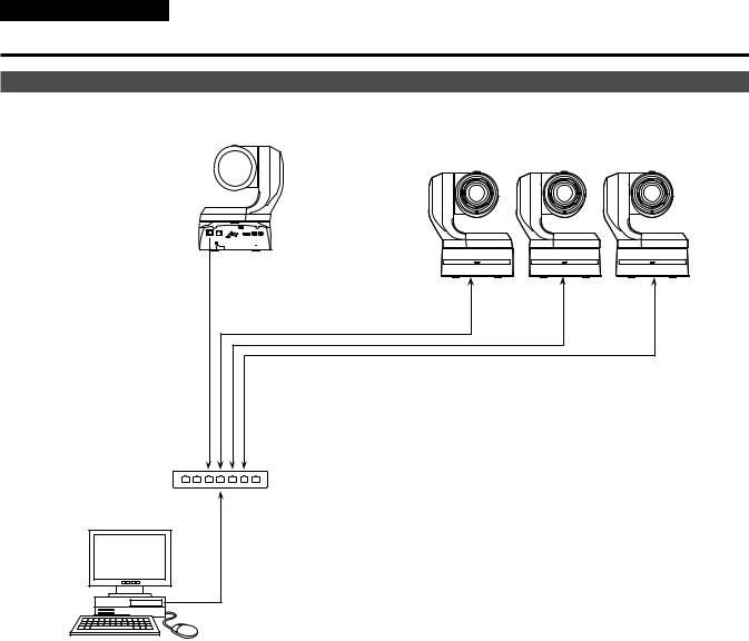
System example 2 (IP control)
AW UE150 |
AW UE150 |
External DC power supply
LAN connector |
|
Genlock signal |
|
generator |
|
SDI video signal |
LAN cable |
|
Monitor 2 |
|
Switching hub |
Monitor 1 |
|
|
LAN cable |
Monitor |
Monitor |
Accessory |
Compact Live Switcher |
AC adaptor |
AW HS50 |
External DC |
Remote Camera Controller |
power supply |
AW RP150 |
21
Installation Instructions
Connections (continued)
System example 3 (IP image transmission, PoE++)
AW UE150
AW UE150
LAN  connector
LAN cable
PoE++ compatible switching hub or PoE++ injector
Personal computer
22
 Loading...