


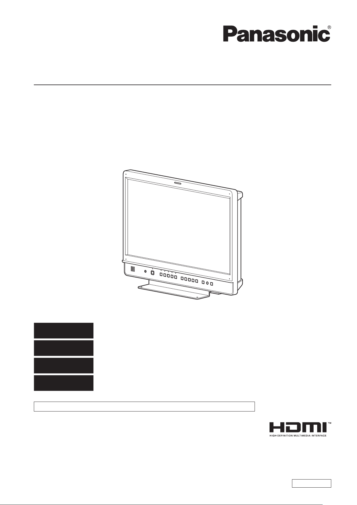
BT-LH2170P
Operating Instructions
LCD Video Monitor
Model No.
Model No.
BT-LH2170P
BT-LH2170E
DEUTSCH
FRANÇAIS
ITALIANO
ESPAÑOL
This manual is also contained as a PDF file on the CD-ROM supplied with the unit. (Back cover)
Before operating this product, please read the instructions carefully and save this manual for future use.
SS0812KT0 -PS
Printed in Japan
Für Erlauterungen in Deutsch, konsultieren Sie bitte die mitgelieferte CD-ROM.
(Zurück Decke)
Pour des explications en français, veuillez vous reporter au CD-ROM fourni.
(Quatrième de couverture)
Per le istruzioni in italiano, vedere il CD-ROM in dotazione. (Retro della copertina)
Para la explicación en español, consulte el CD-ROM suministrado. (Cubierta trasera)
ENGLISH
VQT4M18

3
Read this first ! (for BT-LH2170P)
CAUTION:
The mains plug of the power supply cord shall remain
readily operable.
The AC receptacle (mains socket outlet) shall be installed
near the equipment and shall be easily accessible. To
completely disconnect this equipment from the AC mains,
disconnect the power cable plug from the AC receptacle.
CAUTION:
In order to maintain adequate ventilation, do not install or
place this unit in a bookcase, built-in cabinet or any other
confined space. To prevent risk of electric shock or fire
hazard due to overheating, ensure that curtains and any
other materials do not obstruct the ventilation.
CAUTION:
To reduce the risk of fire or electric shock and annoying
interference, use the recommended accessories only.
CAUTION:
This apparatus can be operated at a voltage in the range
of 100 - 240 V AC. Voltages other than 120 V are not
WARNING:
This equipment must be grounded.
To ensure safe operation, the three-pin plug must be
inserted only into a standard three-pin power outlet which
is effectively grounded through normal household wiring.
Extension cords used with the equipment must have three
cores and be correctly wired to provide connection to
the ground. Wrongly wired extension cords are a major
cause of fatalities. The fact that the equipment operates
satisfactorily does not imply that the power outlet is
grounded or that the installation is completely safe. For
your safety, if you are in any doubt about the effective
grounding of the power outlet, please consult a qualified
electrician.
WARNING:
• To reduce the risk of fire or electric shock, do not expose
this equipment to rain or moisture.
• To reduce the risk of fire or electric shock hazard, keep
this equipment away from all liquids. Use and store
only in locations which are not exposed to the risk of
dripping or splashing liquids, and do not place any liquid
containers on top of the equipment.
intended for U.S.A. and Canada.
CAUTION:
Excessive sound pressure from earphones and
headphones can cause hearing loss.
CAUTION:
This Monitor is for use only with Panasonic Wall Mount
Adaptor, BT-WMA17G. Use with other Wall Mount or Rack
Mount Adaptor is capable of resulting in instability causing
possible injury.
CAUTION:
Check the installation at least once a year.
An improper installation could cause the monitor to fall off
resulting in personal injury.
CAUTION:
Remove the wall mount adaptor when not used.
Otherwise people moving in the vicinity of the monitor
could get caught on the bracket and be injured.
WARNING:
Always keep the stand screws and protective panel
mounting screws out of the reach of infants and small
children.
WARNING:
Installation should only be performed by qualified
installation personnel.
Improper installation may result in the entire apparatus
falling down and causing injury.
indicates safety information.
Notice (U.S.A. only):
Disposal may be regulated in your community due to Environmental considerations. For disposal or recycling information, please
visit Panasonic website: http://www.panasonic.com/environmental or call 1-888-769-0149.
2

Read this first ! (for BT-LH2170P) (continued)
FCC NOTICE (USA)
This device complies with part 15 of the FCC Rules. Operation is subject to the following two conditions:
(1) This device may not cause harmful interference, and (2) this device must accept any interference received, including
interference that may cause undesired operation
CAUTION:
This equipment has been tested and found to comply with the limits for a class A digital device, pursuant to Part 15 of the
FCC Rules. These limits are designed to provide reasonable protection against harmful interference when the equipment is
operated in a commercial environment. This equipment generates, uses, and can radiate radio frequency energy and, if not
installed and used in accordance with the instruction manual, may cause harmful interference to radio communications.
Operation of this equipment in a residential area is likely to cause harmful interference in which case the user will be required
to correct the interference at his own expense.
Warning:
To assure continued FCC emission limit compliance, the user must use only shielded interface cables when connecting to
external units. Also, any unauthorized changes or modifications to this equipment could void the user’s authority to operate it.
indicates safety information.
IMPORTANT SAFETY INSTRUCTIONS
1) Read these instructions.
2) Keep these instructions.
3) Heed all warnings.
4) Follow all instructions.
5) Do not use this apparatus near water.
6) Clean only with dry cloth.
7) Do not block any ventilation openings. Install in accordance with the manufacturer’s instructions.
8) Do not install near any heat sources such as radiators, heat registers, stoves, or other apparatus (including amplifiers) that
produce heat.
9) Do not defeat the safety purpose of the polarized or grounding-type plug. A polarized plug has two blades with one wider than the
other. A grounding-type plug has two blades and a third grounding prong. The wide blade or the third prong are provided for your
safety. If the provided plug does not fit into your outlet, consult an electrician for replacement of the obsolete outlet.
10) Protect the power cable from being walked on or pinched particularly at plugs, convenience receptacles, and the point where they
exit from the apparatus.
11) Only use attachments/accessories specified by the manufacturer.
12) Use only with the cart, stand, tripod, bracket, or table specified by the manufacturer, or sold with the apparatus.
When a cart is used, use caution when moving the cart/apparatus combination to avoid injury from tip-over.
13) Unplug this apparatus during lightning storms or when unused for long periods of time.
14) Refer all servicing to qualified service personnel. Servicing is required when the apparatus has been damaged
in any way, such as power-supply cord or plug is damaged, liquid has been spilled or objects have fallen into the
apparatus, the apparatus has been exposed to rain or moisture, does not operate normally, or has been dropped.
5
Read this first ! (for BT-LH2170E)
WARNING:
This equipment must be earthed.
To ensure safe operation, the three-pin plug must be
inserted only into a standard three-pin power point which
is effectively earthed through normal household wiring.
Extension cords used with the equipment must have
three cores and be correctly wired to provide connection
to the earth. Wrongly wired extension cords are a major
cause of fatalities. The fact that the equipment operates
satisfactorily does not imply that the power point is earthed
or that the installation is completely safe. For your safety,
if you are in any doubt about the effective earthing of the
power point, please consult a qualified electrician.
WARNING:
• To reduce the risk of fire or electric shock, do not expose
this equipment to rain or moisture.
• To reduce the risk of fire or electric shock hazard, keep
this equipment away from all liquids. Use and store
only in locations which are not exposed to the risk of
dripping or splashing liquids, and do not place any liquid
containers on top of the equipment.
WARNING:
Always keep the stand screws and protective panel
mounting screws out of the reach of infants and small
children.
WARNING:
Installation should only be performed by qualified
installation personnel.
Improper installation may result in the entire apparatus
falling down and causing injury.
CAUTION:
The mains plug of the power supply cord shall remain
readily operable.
The AC receptacle (mains socket outlet) shall be installed
near the equipment and shall be easily accessible. To
completely disconnect this equipment from the AC mains,
disconnect the power cable plug from the AC receptacle.
CAUTION:
To reduce the risk of fire or electric shock and annoying
interference, use the recommended accessories only.
CAUTION:
In order to maintain adequate ventilation, do not install or
place this unit in a bookcase, built-in cabinet or any other
confined space. To prevent risk of electric shock or fire
hazard due to overheating, ensure that curtains and any
other materials do not obstruct the ventilation.
CAUTION:
Excessive sound pressure from earphones and
headphones can cause hearing loss.
CAUTION:
This Monitor is for use only with Panasonic Wall Mount
Adaptor, BT-WMA17G. Use with other Wall Mount or Rack
Mount Adaptor is capable of resulting in instability causing
possible injury.
CAUTION:
Check the installation at least once a year.
An improper installation could cause the monitor to fall off
resulting in personal injury.
CAUTION:
Do not remove panel covers by unscrewing them.
To reduce the risk of electric shock, do not remove covers.
No user serviceable parts inside.
Refer servicing to qualified service personnel.
indicates safety information.
EEE Yönetmeliğine Uygundur.
EEE Complies with Directive of Turkey.
[ India Only ]
For the purpose of recycling to facilitate effective utilization of resources, please return this product to a nearby
authorized collection center, registered dismantler or recycler, or Panasonic service center when disposing of this
product.
Please see the Panasonic website for further information on collection centers, etc.
http://www.panasonic.co.in/wps/portal/home
CAUTION:
Remove the wall mount adaptor when not used.
Otherwise people moving in the vicinity of the monitor
could get caught on the bracket and be injured.
4
Read this first ! (for BT-LH2170E) (continued)
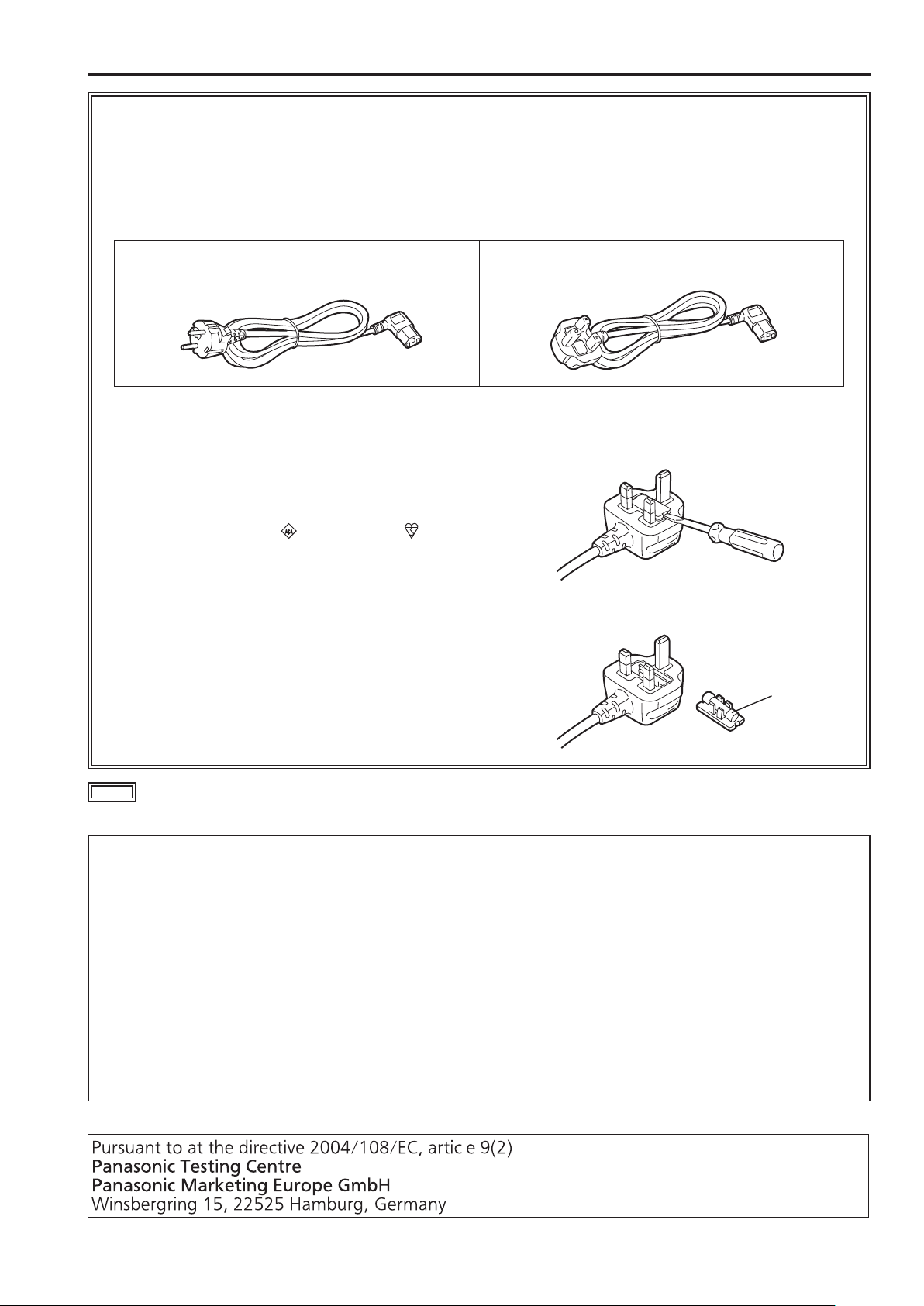
Caution for AC Mains Lead
FOR YOUR SAFETY PLEASE READ THE FOLLOWING TEXT CAREFULLY.
This product is equipped with 2 types of AC mains cable. One is for continental Europe, etc. and the other one is only
for U.K.
Appropriate mains cable must be used in each local area, since the other type of mains cable is not suitable.
FOR CONTINENTAL EUROPE, ETC.
Not to be used in the U.K.
FOR U.K. ONLY
FOR U.K. ONLY
This appliance is supplied with a moulded three pin
mains plug for your safety and convenience.
A 13 amp fuse is fitted in this plug.
Should the fuse need to be replaced please ensure that
the replacement fuse has a rating of 13 amps and that it
is approved by ASTA or BSI to BS1362.
Check for the ASTA mark or the BSI mark
body of the fuse.
If the plug contains a removable fuse cover you must
ensure that it is refitted when the fuse is replaced.
If you lose the fuse cover the plug must not be used
until a replacement cover is obtained.
A replacement fuse cover can be purchased from your
local Panasonic Dealer.
on the
How to replace the fuse
1.Open the fuse compartment with a screwdriver.
2.Replace the fuse.
Fuse
indicates safety information.
Note regarding the Power Management function specified under COMMISSION REGULATION (EC)
No 1275/2008 implementing Directive 2009/125/EC of the European Parliament and of the Council.
This device is designed and manufactured for use at a broadcasting station and/or in a similar environment.
This device is not equipped with a Power Management function or the Power Management function is set to OFF as it will
prevent the device from fulfilling its intended purpose for the reasons below.
1. If the device is a Studio Camera, a Weather Camera, a Mixer or other processor:
A Power Management function may cause the device to suddenly stop during recording or while On Air.
2. If the device is a Studio Monitor:
A Power Management function may cause video for the confirmation of whether a signal is normal, or whether the signal has
been lost, to be un-viewable.
3. If the device is a Camera Recorder:
A professional camera recorder must be able to start quickly at any time, but a Power Management function will cause an
increase in the time taken to resume from Stand-by mode.

Read this first ! (for BT-LH2170E) (continued)
EMC NOTICE FOR THE PURCHASER/USER OF THE APPARATUS
1. Applicable standards and operating environment
The apparatus is compliant with:
• standards EN55103-1 and EN55103-2 2009, and
• electromagnetic environments E1, E2, E3 and E4.
2. Pre-requisite conditions to achieving compliance with the above standards
<1> Peripheral equipment to be connected to the apparatus and special connecting cables
• The purchaser/user is urged to use only equipment which has been recommended by us as peripheral equipment to be
connected to the apparatus.
• The purchaser/user is urged to use only the connecting cables described below.
<2> For the connecting cables, use shielded cables which suit the intended purpose of the apparatus.
• Video signal connecting cables
Use double shielded coaxial cables, which are designed for 75-ohm type high-frequency applications, for SDI (Serial
Digital Interface).
Coaxial cables, which are designed for 75-ohm type high-frequency applications, are recommended for analog video
signals.
• Audio signal connecting cables
If your apparatus supports AES/EBU serial digital audio signals, use cables designed for AES/EBU.
Use shielded cables, which provide quality performance for high-frequency transmission applications, for analog audio
signals.
• Other connecting cables (IEEE1394, USB)
Use shielded cables, which provide quality performance for high-frequency applications, as connecting cables.
• When connecting to the DVI signal terminal, use a cable with a ferrite core.
• If your apparatus is supplied with ferrite core(s), they must be attached on cable(s) following instructions in this manual.
3. Performance level
The performance level of the apparatus is equivalent to or better than the performance level required by these standards.
However, the apparatus may be adversely affected by interference if it is being used in an EMC environment, such as an
area where strong electromagnetic fields are generated (by the presence of signal transmission towers, cellular phones, etc.).
In order to minimize the adverse effects of the interference on the apparatus in cases like this, it is recommended that the
following steps be taken with the apparatus being affected and with its operating environment:
1. Place the apparatus at a distance from the source of the interference.
2. Change the direction of the apparatus.
3. Change the connection method used for the apparatus.
4. Connect the apparatus to another power outlet where the power is not shared by any other appliances.
Декларація про Відповідність
Вимогам Технічного Регламенту Обмеження Використання деяких Небезпечних Речовин в електричному та електронному
обладнанні
(затвердженого Постановою №1057 Кабінету Міністрів України)
Виріб відповідає вимогам Технічного Регламенту Обмеження Використання деяких Небезпечних Речовин в електричному та
електронному обладнанні (ТР ОВНР).
Вміст небезпечних речовин у випадках, не обумовлених в Додатку №2 ТР ОВНР, :
1. свинець(Pb) – не перевищує 0,1 % ваги речовини або в концентрації до 1000 частин на мільйон;
2. кадмій (Cd)– не перевищує 0,01 % ваги речовини або в концентрації до 100 частин на мільйон;
3. ртуть(Hg) – не перевищує 0,1 % ваги речовини або в концентрації до 1000 частин на мільйон;
4. шестивалентний хром (Cr6+ ) – не перевищує 0,1 % ваги речовини або в концентрації до 1000 частин на мільйон;
5. полібромбіфеноли (PBB) – не перевищує 0,1% ваги речовини або в концентрації до 1000 частин на мільйон;
6. полібромдефенілові ефіри (PBDE) – не перевищує 0,1 % ваги речовини або в концентрації до 1000 частин на мільйон.
6
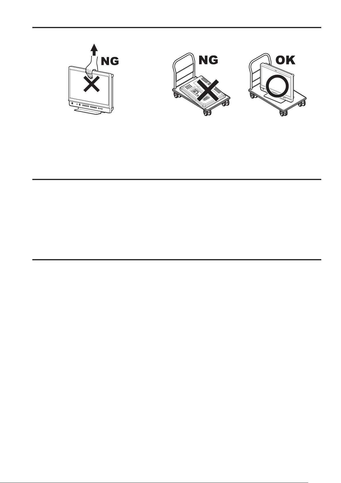
Transportation precautions
Do not try to lift the monitor by grabbing the LCD panel. Do not place the monitor face down during transportation to prevent
damaging it. Keep it upright.
Do not expose the LCD panel to strong pressure or pressure from pointed objects. Take care especially during transportation.
Exposing the LCD panel to strong pressure may result in blurring or other damage.
About this instruction manual
• This instruction manual refers to BT-LH2170P/BT-LH2170E as “this unit.”
• The illustrations, explanatory drawings, and other figures included in this instruction manual are for illustrative purposes only and
may differ from actual appearance.
• HDMI, the HDMI logo, and High-Definition Multimedia Interface are trademarks or registered trademarks of HDMI Licensing, LLC in
the United States and/or other countries.
• Adobe
• Page references are indicated as (→ page 00) in this manual.
®
Reader® is a trademark of Adobe Systems Incorporated.
Precautions for Use
• The LCD monitor is manufactured with high-precision technology and has an effective pixel count of over 99.99 %. However, less than 0.01 % of pixels may be stuck or dead. This is
not a malfunction and does not affect recorded images.
• When a still image is displayed for an extended period of time,
it may generate a temporary afterimage (phosphor burn-in).
(However, such images can be removed by displaying normal
video for a while.)
• LCD response speed and brightness vary with ambient temperatures.
• Do not install the unit where it is exposed to direct sunlight. It
may damage the cabinet and LCD screen.
• Leaving the unit in a location exposed to high temperature and
humidity for an extended period of time may damage the LCD
screen and cause blurring.
• Streaks of light may be seen in the area between the edge of
the screen and the frame; this is normal and not a malfunction.
• The LCD panel is covered by the packaging material to protect
it from damage during transportation and when unpacking it.
Remove the packaging material before use.
• This unit does not support VIERA Link. When the unit is connected to a VIERA-Link-compatible device via an HDMI cable,
VIERA Link functions on the other devices may not operate
properly.
• Do not install the unit in locations where enough space cannot
be provided around it as heat may build up inside preventing
normal operation. Be sure to provide enough space around
the unit.
• Exposing the LCD screen to intense light sources will impair
its characteristics and lower image quality.
• In an environment exposed to drastic temperature fluctuations,
condensation may build up on and inside the LCD screen.
This may lower the quality of the screen and may damage it.
• Some video images may appear blurred on the screen.
• Using the unit near a wireless transmitter, high-voltage equipment, speakers, large motors or other devices or exposing it
to static electricity could cause electromagnetic interference
and distort audio and video reception.
7

9
Table of Contents
Read this first ! (for BT-LH2170P) ...........................................2
Read this first ! (for BT-LH2170E) ...........................................4
Transportation precautions .....................................................7
About this instruction manual .................................................7
Precautions for Use..................................................................7
Standard accessories · Optional units ...................................9
Outline .......................................................................................9
Dimensions .............................................................................10
Controls and Their Functions ...............................................11
Video monitor ........................................................................11
Front panel ............................................................................12
Rear panel .............................................................................13
Power supply ..........................................................................14
Connecting the power cable ..................................................14
Detaching and Attaching the Stand ......................................15
Detaching the stand ..............................................................15
Attaching the stand ................................................................15
On-screen Display ..................................................................16
Operating status display ........................................................16
Main menu (MAIN MENU)/FUNCTION menu/
INPUT SELECT menu displays .........................................16
Picture adjusting (PICTURE) menu display ..........................17
Audio volume display ............................................................17
Sharpness display .................................................................17
FUNCTION display ................................................................17
Audio volume bar meter display ............................................18
Time code (TC) display .........................................................18
Closed caption (CC) display ..................................................19
IMD (in monitor display) display ............................................19
How to Use the On Screen Menu ..........................................20
Main menu (MAIN MENU) .....................................................20
FUNCTION menu ..................................................................20
INPUT SELECT menu ...........................................................20
Picture adjusting (PICTURE) menu .......................................21
Audio volume .........................................................................21
User Data .................................................................................22
Saving user data ...................................................................22
Loading user data ..................................................................22
Main Menu ...............................................................................23
Menu configuration ................................................................23
2D/3D ASSIST ......................................................................24
MARKER ...............................................................................24
MARKER types .....................................................................26
VIDEO CONFIG ....................................................................27
SYSTEM CONFIG .................................................................30
Performing AUTO CALIBRATION .........................................33
RESET operation ..................................................................33
FUNCTION ............................................................................34
GPI ........................................................................................43
INPUT SELECT .....................................................................44
AUDIO ...................................................................................45
DISPLAY SETUP ..................................................................46
CONTROL .............................................................................48
HOURS METER ....................................................................48
3D Assist Mode .......................................................................49
MIRROR (Left/Right and Top/Bottom inversion) ...................50
SHIFT (Horizontal and Vertical Shift) ....................................50
COMPARISON (Composition Check) ...................................51
CONVERGENCE (Convergence Check) ..............................51
COLOR (Color Check) ..........................................................52
ZOOM FOCUS (Zoom and Focus Check) ............................52
VERTICAL (Vertical Offset Check) ........................................53
OVERLAY (Parallax Check) ..................................................53
Setting Item Restrictions .......................................................55
REMOTE Specifications .........................................................60
GPI input terminal ..................................................................60
RS-232C input terminal .........................................................62
RS-485 input/output terminal .................................................63
Maintenance Inspections .......................................................70
Error and Warning Information .............................................71
Maintenance ............................................................................71
Specifications .........................................................................72
Index ........................................................................................78
8

Standard accessories · Optional units
Standard accessories
Power cable x 1 (BT-LH2170P)
Power cable x 2 (BT-LH2170E)
Stand (already attached to the product) x 1
Stand screws (already attached to the product) x 3
CD-ROM x 1
Protection panel mounting screws (8 mm long M3 screws) x 4
• The customer can use these screws for permanent attachment of a protective panel designed for the monitor. (→page 11)
• Tightening torque: Tighten to about 30 N·cm or less
<Note>
After unpacking the monitor, dispose of the AC cord cap (BT-LH2170E only) and packaging material in an appropriate manner.
Optional units
• BT-WMA17G wall mount adapter (Leave installation of the wall mount adapter to authorized personnel.)
Outline
The BT-LH2170P/BT-LH2170E is a compact, flat panel LCD monitor for broadcast and industrial applications, equipped with a
54.6 cm (21.5 inch) (effective display area) LCD display.
High performance LCD panel
This product incorporates a full HD (1920 x 1080) LCD panel.
It offers excellent color reproduction, a wide viewing angle,
and a fast response time.
Superb Moving Image Quality Achieved by New Image
Processing Engine
• A 3D Look Up Table (LUT) and a 10-bit image processing
engine facilitate accurate and smooth gradation from low to
high brightness levels.
• The inclusion of an I/P conversion circuit with a low delay of
less than one field minimizes the delay time between signal
input and monitor display.
• The use of a diagonal line compensation circuit reduces
image degradation in the vertical direction and jagged noise
on diagonal lines.
• The high-speed moving image response time provides vivid
and clear image display.
• Gamma compensation is performed for each monitor.
Includes 3D Assist Functions
Various assist functions are included to allow connecting
the left and right connectors of a 3D camera to the two SDI
inputs and capturing 3D images that are easier to view on a
2D monitor. These functions also make camera adjustments
easier and reduce the preparation time required for 3D shooting.
Wide Variety of Functions and Interfaces
• Equipped with 3G-SDI, SDI (HD/SD compatible), HDMI,
VIDEO, and DVI-I inputs.
• FOCUS-IN-RED function (Displayed abbreviated to F-IN-R
in the [PICTURE] (picture adjusting) menu.)
Focusing the camera is extremely easy because the area of
the image in focus is displayed in red to make it easy to see
what is in focus.
• WFM (Y/R/G/B) and vectorscope display functions
Capable of showing a Y/R/G/B waveform display for input
signals (3G-SDI, SDI, HDMI, VIDEO, and DVI-I inputs) and
a vectorscope display (for 3G-SDI and SDI inputs).
• Audio volume bar meter display function
There are level displays for embedded 3G-SDI, SDI and
HDMI audio signals and analog audio signals. Furthermore,
support is also included for reference point setting, peak
hold, and overrange display.
The incorporation of a speaker and a HEADPHONES output
jack means you can check the audio. There is also a menu
for selecting channels.
• Closed caption function
The captions added to video signals can be displayed during SDI and VIDEO input.
• 2-screen display function
The screen can be split into two to allow you to make a
screen comparison for the same input connectors and same
format. (SUB WINDOW function)
It can display two SDI inputs simultaneously in two
windows. (TWO WINDOW function)
One input signal can be displayed on two windows for
3G-SDI, SDI, HDMI, VIDEO and DVI-I input VIDEO formats
in combination with FOCUS-IN-RED, Y MAP, ZEBRA and
other functions to simplify camera adjustments. (PICTURE
ASSIST function)
• Cross hatch display function
This function displays markers at regular vertical and horizontal intervals to facilitate easy composition.
• External remote control
RS-485, RS-232C and GPI remote control terminals are
provided.
A loop-through connection using the RS-485 input and
output terminals allows control of multiple monitors (up to 32
monitors).
• IMD (in-monitor display) display
The RS-485 interface allows you to display text and the tally
indication on the monitor.
9
11
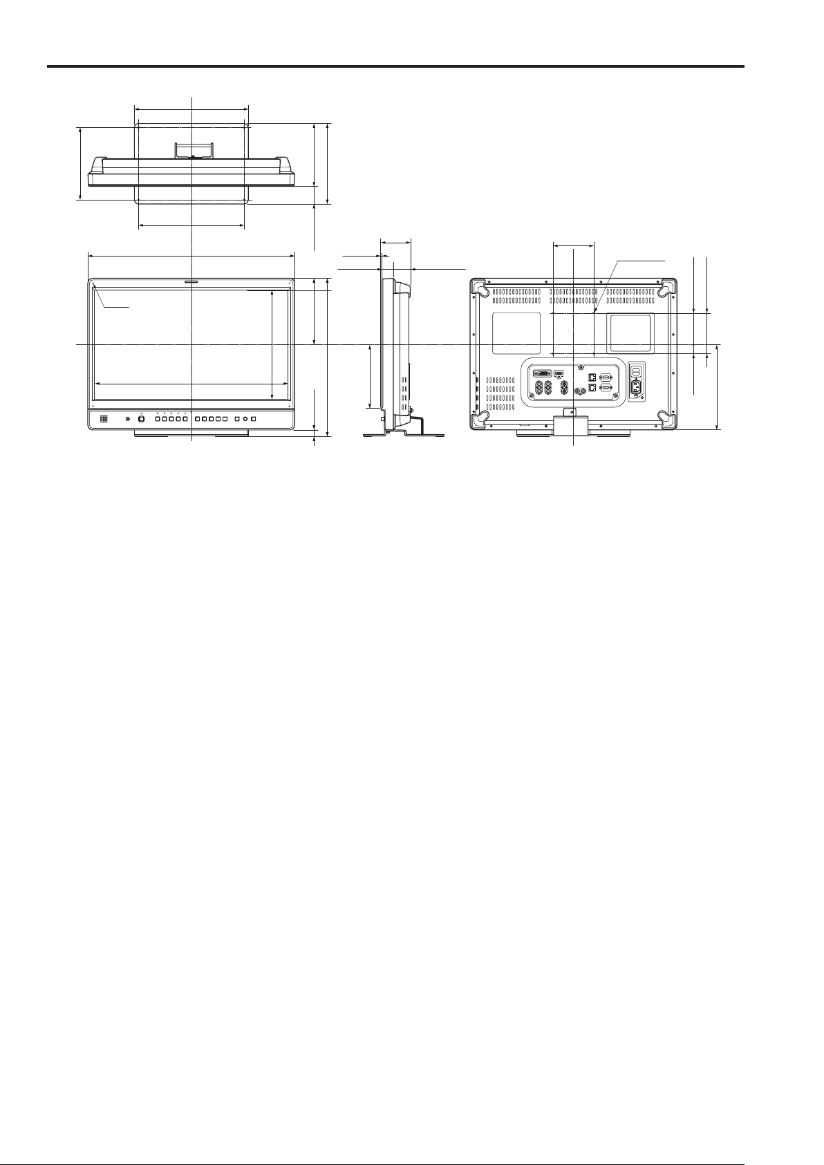
Dimensions
178(7)
Unit: mm (inches)
280(11)
154.9 (6-1/8)43.1 (1-5/8)
198(7-13/16)
4-M3
260(10-1/4)
510(20-1/16)
475.2(18-5/8)
267.3(10-1/2)
2.5(1/8)
27(1-1/16)
163.5(6-7/16)15(9/16)
388(15-1/4)
72
(2-13/16)
156(6-1/8)
42.5(1-5/8)
100
(3-15/16)
4-M4 P=0.7
100(3-15/16)
77.8(3-1/16)22.2(7/8)
209.5(8-1/4)
• When the unit will be permanently installed in one place, we recommend securing it in place using the screw holes at the bottom of
the stand.
10

Controls and Their Functions
1 2
Video monitor
Front panel Rear panel
Front panel
(→page 12)
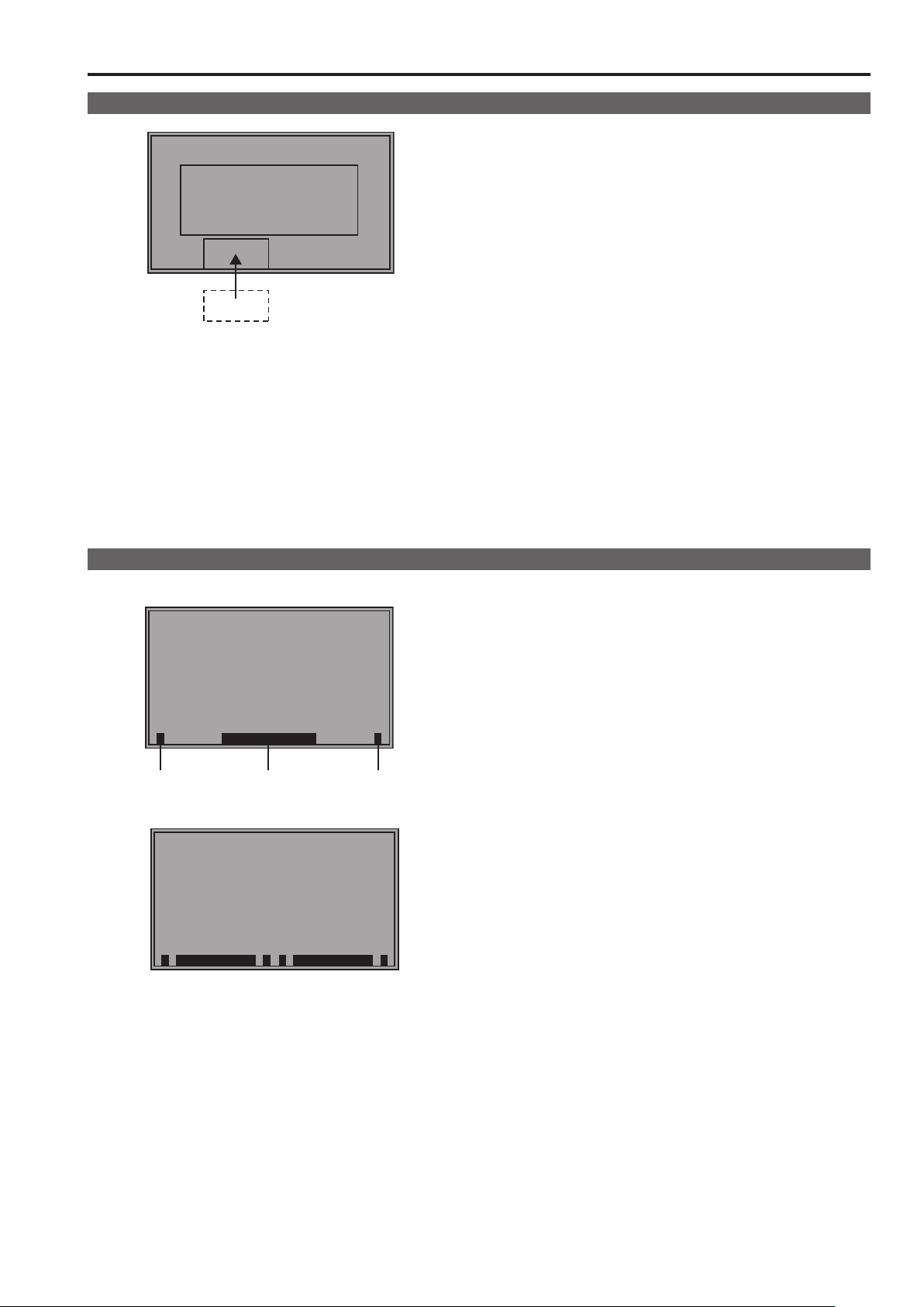
1
Tally Lamp (Red and Green)
Can be lit by a control signal (red tally and green tally) via
GPI.
When both the red and green tally are triggered together,
the lamp lights amber.
2
Protective panel mounting screw holes (4 holes)
Four screw holes have been provided to enable attachment
of a permanent protective panel.
<Note>
The LCD panel is shipped in packaging material to protect it
from damage during unpacking and transportation. Remove
the packaging material before using the monitor.
Rear panel
(→page 13)
Power Supply
(You can switch between AC
and DC (→page 14))
11
Controls and Their Functions (continued)
13
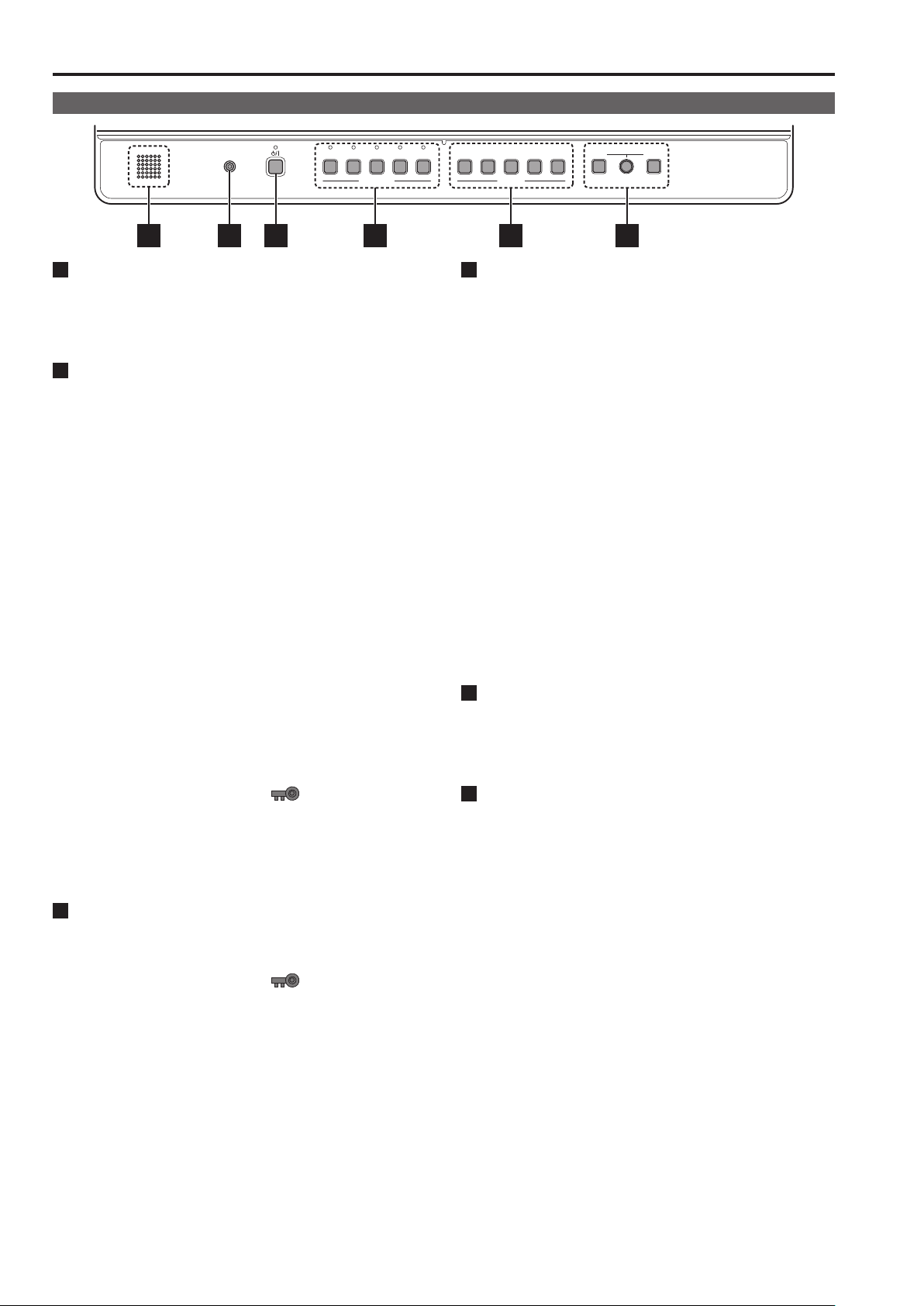
Front panel
HEADPHONES
SDI 1 SDI 2 HDMI DVI-I
VIDEO
INPUT SELECT
5 16 2 3 4
1
POWER <8> switch
Switches the power supply ON/OFF. When the power is on,
the LED (green) lights.
To turn the power off, press and hold the switch for at least
three seconds.
2
INPUT SELECT buttons
Selects the signal input line. The green LED light above the
pressed button indicates the selected input signal.
VIDEO : Video input
SDI1 : Serial digital interface input (compatible with 3G/
HD/SD)
SDI2 : Serial digital interface input (HD/SD compatible)
HDMI : HDMI input (HDCP compatible)
DVI-I : DVI-I input (HDCP compatible)
• When the power is turned on, the input line used when the
• In 3D assist and TWO WINDOW mode, the input is fixed
• Switching the [2D/3D ASSIST] menu from [3D ASSIST] to
• Switching the TWO WINDOW function from ON to OFF
• When the control lock is on, the
• When INT-SG (internal chart for adjustment [Color Bar
3
FUNCTION button
FUNCTION1 to FUNCTION5:
Press to use function assigned to the FUNCTION button
using a menu.
• When the control lock is on, the
• Selects one of the following four input signals:
digital video or PC signal, analog video or PC
signal.(→page 44)
power was last turned off is selected.
to SDI1/SDI2 and the input line cannot be changed. (Then
both the SDI1 and SDI2 LEDs go on.)
[2D] will return the input line to the previous 2D setting.
will return the input line to the previous OFF setting. However, turning on the SUB WINDOW function or the PICTURE ASSIST function when the TWO WINDOW function
is on, activates SDI1 operation, and when the 2-screen
display function is off, the SDI1 input line is used.
mark appears and
input lines cannot be changed.(→page 48)
+ Grayscale]) is selected, all LEDs above the <INPUT
SELECT> button are off. Use the [INPUT SELECT] menu
to select INT-SG. (→page 20)
mark appears to
indicate that FUNCTION operation is disabled.(→page 48)
1 2
3 4 5
FUNCTION
4
MENU button, rotary knob (with push-on switch (PIC-
MENU RETURN
VOLUMEPICTURE
TURE) and RETURN/VOLUME button (→page 16)
Use these buttons to display menus, select and adjust settings and perform menu selections.
MENU: Press to display or exit the [TOP MENU]
([MAIN MENU] (main menu), [FUNCTION]
menu and [INPUT SELECT] menu).
Rotary knob: Turn the knob clockwise or counterclockwise
to move the cursor up or down or to change
set values.
Press the knob to start changing set values, to
confirm them and to open submenus.
RETURN: Press to return to the previous menu or cancel
to recover a previously set value.
When no menu is open, press the rotary knob <PICTURE>
or <RETURN/VOLUME> button to open a menu other than
the [TOP MENU].
PICTURE: When no menu is open, press the rotary knob
to open the [PICTURE] (picture adjusting)
menu.(→page 17)
VOLUME :
When no menu is open, press the <RETURN/
VOLUME> button to open the audio volume bar
meter.(→page 17)
5
Speaker (monaural)
1
*
Enables monitoring of analog AUDIO, SDI and HDMI signal
inputs.
• Connecting headphones to the HEADPHONES output jack
turns off the speaker.
6
HEADPHONES output jack (M3 stereo mini jack)
Allows you to connect headphones to monitor analog audio,
SDI and HDMI signal inputs.
• The sound volume and sound quality will depend on the
headphones.
• In 3D assist mode, you can monitor the left (L) channel of
*1
SDI1 audio.
• In TWO WINDOW mode, you can monitor SDI1 and SDI2
audio selected using [AUDIO OUT SEL.].
1
*
12
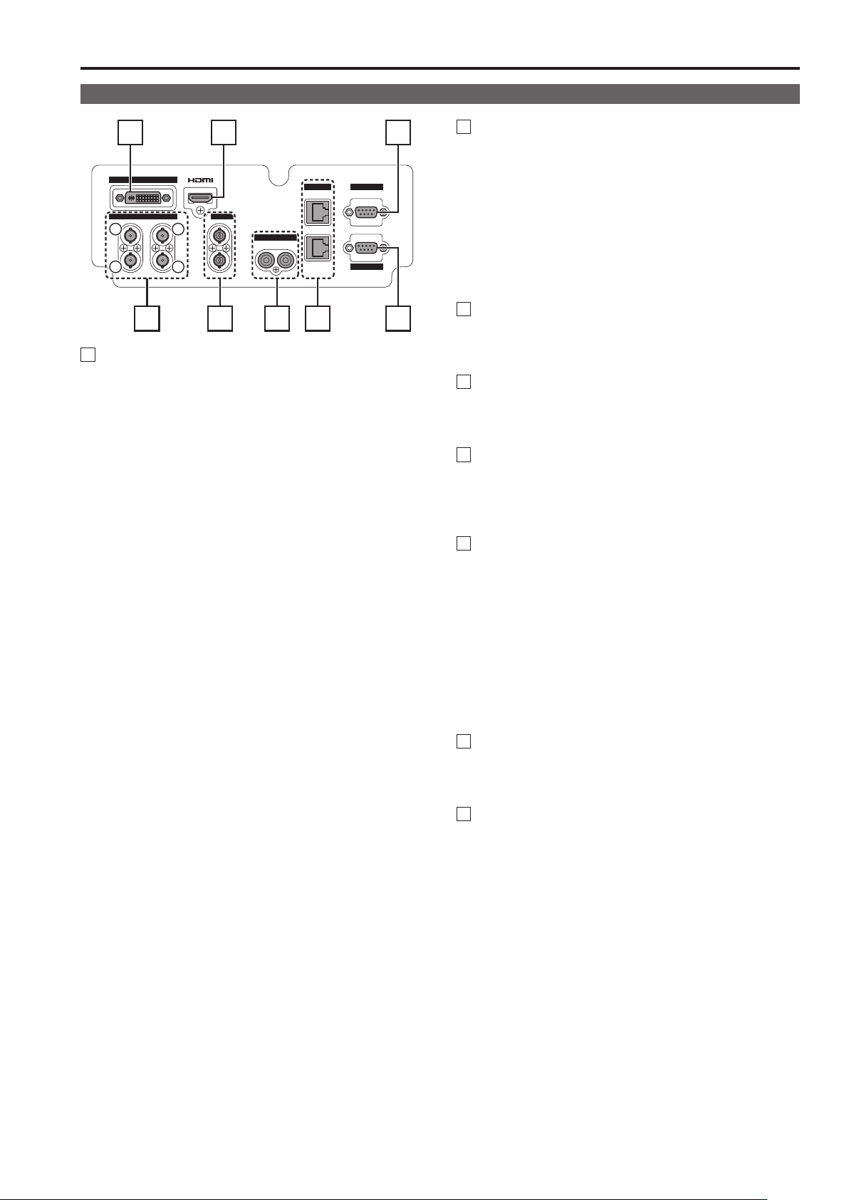
Controls and Their Functions (continued)
Rear panel
3 4 7
DVI-I
SDI VIDEO
1
2
1
IN
OUT
2
(3G)
3
IN
OUT IN
4
R L
AUDIO
RS-485 GPI
IN
OUT
RS-232C
2 6 81 5
1
SDI terminal
A SDI1 (3G/HD/SD) input terminal (BNC)
This is the SDI input terminal. (Compatible with 3G-SDI
and 3G/HD/SD automatic switching)
In 3D assist mode, input images for the left eye (L).
B SDI1 active through output terminal (BNC)
This terminal outputs SDI1 input as is.
C SDI2 (HD/SD) input terminal (BNC)
This is the SDI input terminal. (Compatible with HD/SD
automatic switching)
In 3D assist mode, input images for the right eye (R).
D SDI2 active through output terminal (BNC)
This terminal outputs SDI2 input as is.
• When this output is used to daisy-chain
tors, the quality of the original signal, cable length, the
number of connected devices and other factors all come
into play to deteriorate picture quality and introduce noise.
Daisy-chain:
*1
Refers to connecting the through-out signal from a
device to the input of a second, third or more devices
in a linear series, thus using a single signal in multiple
devices.
• Use a 5C-FB or equivalent cable to make connections to
an SDI terminal.
1
multiple moni-
*
2
VIDEO terminal (BNC)
*2*
3
IN : This is the VIDEO signal (composite signal) input
terminal.
OUT : This is the input signal through-out terminal.
Unless a cable is connected to the VIDEO OUT terminal,
*2
the VIDEO IN terminal is automatically terminated at
75 Ω. Connecting a cable releases this termination.
Since a connection to the through-out terminal releases the
*3
75 Ω termination of the unit, the level of the VIDEO signal
input to the unit may become too large depending on the
connected device.
3
DVI-I terminal
This is the DVI-signal input terminal.
• Use double shielded cable for making connections to a
DVI-I terminal.
4
HDMI terminal (Type A)
This is the HDMI input terminal.
• Use double-shielded cable for making connections to an
HDMI terminal.
5
AUDIO input terminal (pin jack)
This is the common audio input terminal for all video input
terminals.
• Use shielded cable for making connections to an AUDIO
input terminal.
6
RS-485 input/output terminal (RJ-45)
External control is possible by using an RS-485 signal.
• Use shielded cable for making connections to an RS-485
input/output terminal.
• Make sure that the cable is fully inserted in the terminal
and cannot easily be pulled out.
• A loop-through connection using the RS-485 input and
output terminals allows operation of multiple monitors (up
to 32 monitors).
• Connect a terminator (120 Ω) between the first and second pin of the RS-485 OUT terminal on the last monitor in
the chain.
7
GPI input terminal (D-SUB, 9 pins)
External control is possible by using a GPI signal.
• Use shielded cable for making connections to the GPI
input terminal.
8
RS-232C input terminal (D-SUB, 9 pins)
External control is possible by using an RS-232C signal
• Use shielded cable for making connections to an RS-232C
input terminal.
13
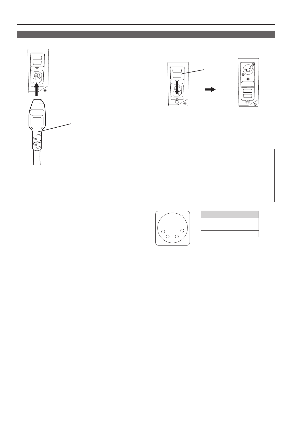
15
Power supply
Connecting the power cable
1.
Attach the power cable to the unit.
Power cable
2. Connect the power cable to the power outlet.
When using external DC power (12 V DC)
You can slide open the power cover to switch from AC input
to external DC input.
Power cover
<Note>
• If the power cover has come off or been removed, do not use
the monitor with the power supply connected to both AC input
and DC input terminals.
• Use a shielded DC cable that is not longer than 2 m. A cable
that is 2 m or longer may cause screen noise.
Before using an external DC power supply, be sure to check
that the rating of the external DC power supply suits the
power requirements of this monitor.
Check the pin arrangements of the DC output terminal of the
external DC power supply and those of the DC IN socket of
this monitor to ensure that a connection will maintain the correct polarity.
If +12 V is accidentally connected the GND terminal, fire or
injury could result.
1
External DC input
terminal
4
2 3
Pin number Signal
1 GND
2, 3 ―
4 +12 V
14
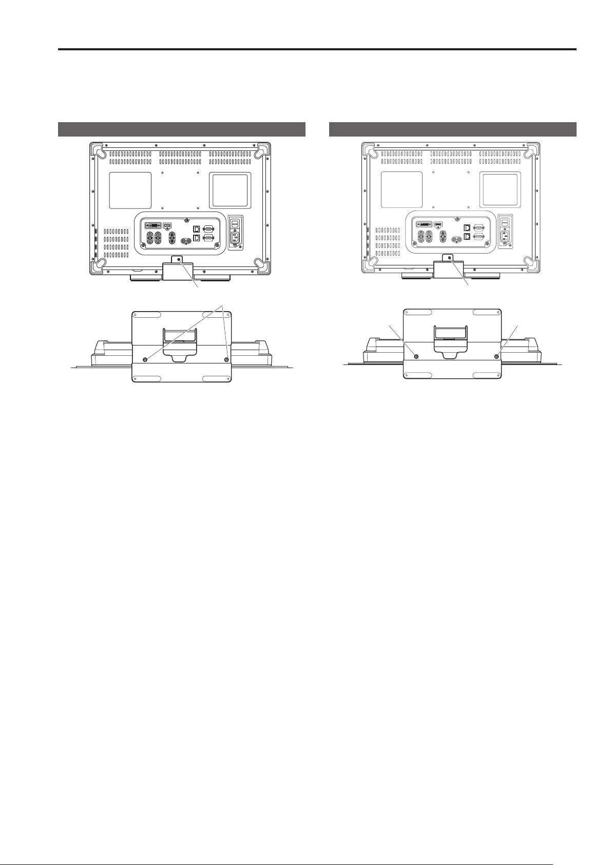
Detaching and Attaching the Stand
The stand is detachable.
• When detaching and attaching the stand, it is recommended that you place the monitor flat on the edge of a desk or table with a soft
cloth or similar material spread underneath.
• The stand is specifically designed for this monitor and cannot be used with other monitors. The stands supplied with the BT-LH1700W/
1710/1760 series cannot be used with this unit.
Detaching the stand
Stand screws
Unscrew the stand screws (three) using a Phillips screwdriver.
• After detaching, store the stand and the stand screws for the
stand in a location easily accessible when required.
Attaching the stand
③
②
①
1. Align the holes in the stand with those in the monitor.
2. Use a Phillips screwdriver to secure the stand to the
monitor with the stand screws (three).
• Install the stand screws in the (① to ③) order shown in the
figure.
15
17
On-screen Display
The screen shows the operation status display, the main menu (MAIN MENU) / FUNCTION menu / INPUT SELECT menu displays,
picture adjusting (PICTURE) menu display, audio volume display, sharpness display, FUNCTION display, audio volume bar meter
display, time code (TC) display, closed caption (CC) display, IMD (in monitor display) display and other information.
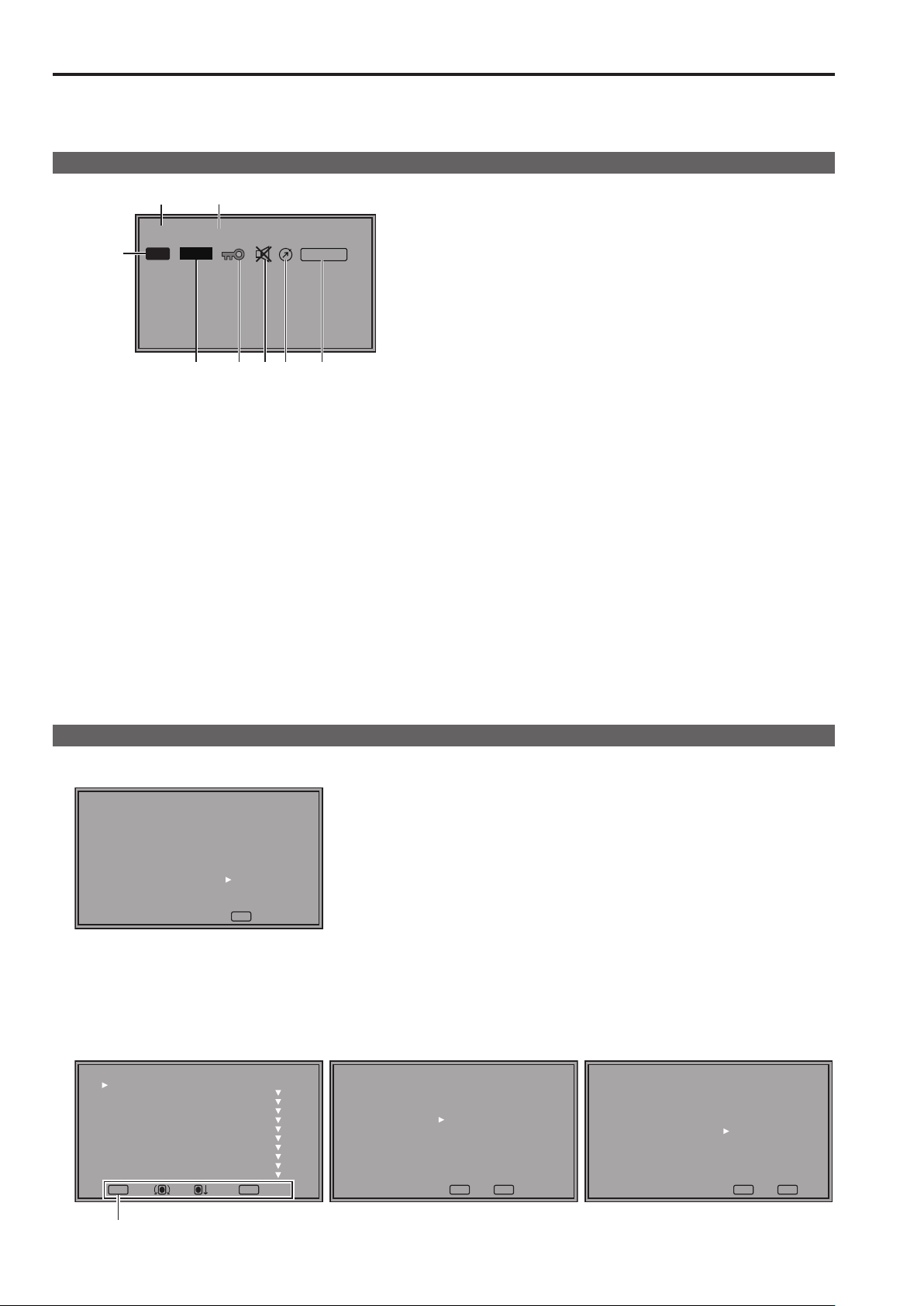
Operating status display
1
SDI1 1080/60i 3G:A
3
P-P
FILM
4
526 7 8
ANALOG
<Note>
• Use [STATUS DISPLAY] in the [SYSTEM CONFIG] menu to
set the display status.(→page 30)
• Icons meeting the 3 to 8 display requirements appear aligned
to the left.
• [UNSUPPORT SIGNAL] and [NO SIGNAL] may not be properly displayed.
• For details on the display of names and signal formats of
assist functions in 3D assist mode, refer to “3D Assist Mode”
(→page49).
In 3D assist mode, the various indications (4 to 8) can be
displayed as well.
1. The selected input line (→pages 12 and 20)
• Displays [VIDEO], [SDI1], [SDI2], [HDMI], [DVI-I] ([YPBPR]/
[RGB-COMP.]/[DVI-VIDEO]/[DVI-COMP.]) and [INT-SG].
2. Signal format
• [UNSUPPORT SIGNAL] appears if an unsupported signal
is input.
It may also indicate that the format selected in the [INPUT
SELECT] menu does not match the input signal.
• [NO SIGNAL] appears when no signal is input.
• The level of a 3G-SDI signal input is displayed to the right of the
signal format.
3. Various indications (PIXEL TO PIXEL mode)
• This indicates that the PIXEL TO PIXEL mode is engaged.
4. Various indications (FILM mode)
• This indicates that [GAMMA SELECT] in [VIDEO CONFIG]
is set to [FILM].
5. Various indications (Lock setting)
• This indicates that the front operations are locked.(→page 48)
6. Various indications (mute indication)
• Indicates that the speaker and headphones are muted.
(→page 21)
7. Various indications (indication of picture adjustment
change)
• Indicates that picture adjustments ([PEAKING]/[PHASE]/
[CHROMA]/[BRIGHT]/[CONTRAST]/[BACKLIGHT]) have
been changed from the values assigned using [SETUP
LOAD] or [POWER ON SETUP].(→page 21)
8. Various indications (ANALOG mode)
• Indicates that the operating mode has been set to analog
audio input using [INPUT SELECT] in the [AUDIO] menu.
Main menu (MAIN MENU)/FUNCTION menu/INPUT SELECT menu displays
1.
Press <MENU> when no menu is displayed.
• The [TOP MENU] appears.
[TOP MENU]
MAIN MENU
FUNCTION
INPUT SELECT
MENUEXIT
2. Turn the rotary knob <PICTURE> to select a menu ([MAIN MENU], [FUNCTION], [INPUT SELECT]) and press the rotary
knob <PICTURE>.
• For details on how to operate menus, refer to “How to Use the On Screen Menu” (→page20).
• In 3D assist and TWO WINDOW mode, the input is fixed to SDI1/SDI2 display and the [INPUT SELECT] menu cannot be selected.
[MAIN MENU] [FUNCTION] [INPUT SELECT]
[MAIN MENU]
2D/3D ASSIST
MARKER
VIDEO CONFIG
SYSTEM CONFIG
FUNCTION
GPI
INPUT SELECT
AUDIO
DISPLAY SETUP
CONTROL
HOURS METER
MENUEXIT
RETURN
2D
[FUNCTION]
F1:WFM/VECTOR
F2:TWO WINDOW
F3:FOCUS-IN-RED
F4:TIME CODE
F5:LEVEL METER
RETURNSEL. ENTER
WFM/VECTOR OFF
MENUEXIT
RETURN
RETURN
[INPUT SELECT]
VIDEO
SDI1
SDI2
HDMI
DVI-I
INT-SG
MENUEXIT
RETURN
RETURN
Displays instructions on <MENU> button operations.
16
On-screen Display (continued)
3. To close a menu, press <MENU>.
• The menu display disappears after approx. 2 minutes of inaction. (The value shown before the display clears is confirmed.)
Picture adjusting (PICTURE) menu display
1. Press rotary knob <PICTURE> when no menu is dis-
[PICTURE]
SETTING[FACTORY]
PEAKING
PHASE
CHROMA
BRIGHT
CONTRAST
BACKLIGHT
F-IN-R
MENUEXIT
31
30
30
52
80
15
0
A
*
B
*
A: File names called by [SETUP LOAD] or [POWER ON
SETUP] appear on the screen to the right of [SETTING].
B: When picture adjustments ([PEAKING]/[PHASE]/[CHRO-
MA]/[BRIGHT]/[CONTRAST]/[BACKLIGHT]) have been
changed from the values assigned using [SETUP LOAD]
or [POWER ON SETUP], an asterisk (
of the menu name.
) appears to right
*
played.
• The [PICTURE] (picture adjusting) menu appears.
• For details on how to operate menus, refer to “How to Use
the On Screen Menu” (→page20).
2. To close a menu, press <MENU>.
• This display disappears after approx. 10 seconds of inaction. (The value shown before the display clears is confirmed.)
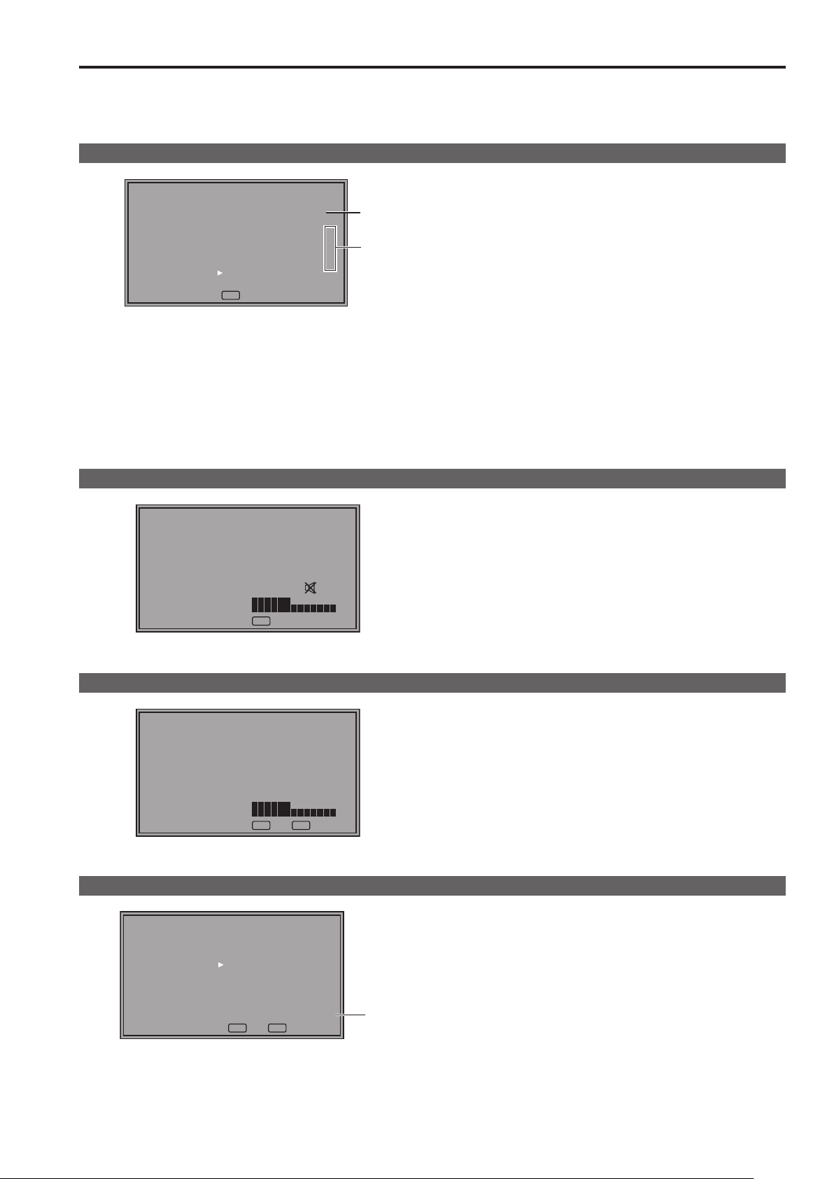
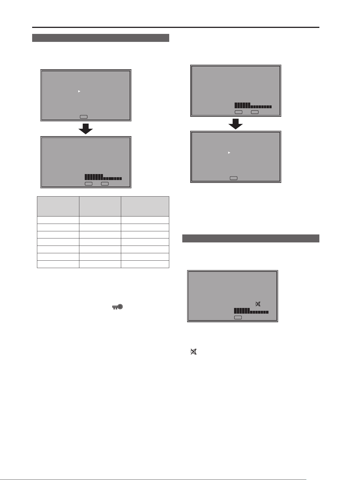
Audio volume display
Sharpness display
[VOLUME] 30
MENUEXIT
[SHARPNESS H] 14
RETURN
MENUEXIT
RETURN
1. Press <RETURN / VOLUME> when no menu is displayed.
• The audio volume bar meter appears.
• For details on how to use the audio volume, refer to“How to
Use the On Screen Menu” (→page20).
2. To close a menu, press <MENU> or the rotary knob
<PICTURE>.
• This display disappears after approx. 10 seconds of inaction. (The value shown before the display clears is confirmed.)
• Indicates the [SHARPNESS H] and [SHARPNESS V] setting
of the [VIDEO CONFIG] menu.
• When no operation is performed for approx. 2 minutes, the set
value is confirmed and the display disappears.
FUNCTION display
[FUNCTION]
F1:WFM/VECTOR
F2:TWO WINDOW
F3:FOCUS-IN-RED
F4:TIME CODE
F5:LEVEL METER
WFM/VECTOR OFF
MENUEXIT
RETURN
RETURN
• Use the [FUNCTION] menu to set up functions.
• When [FUNCTION DISPLAY] (→page 35) is set to [ON1] or
[ON2], press any of the <FUNCTION1> to <FUNCTION5>
buttons to display the status of functions assigned to the
FUNCTION buttons.
• When no operation is performed for approx. 2 seconds, the
A
set value is confirmed and the display disappears.
• "A" indicates operating status.(→page37 “Functions displayed
during FUNCTION button operation”)
On-screen Display (continued)
19
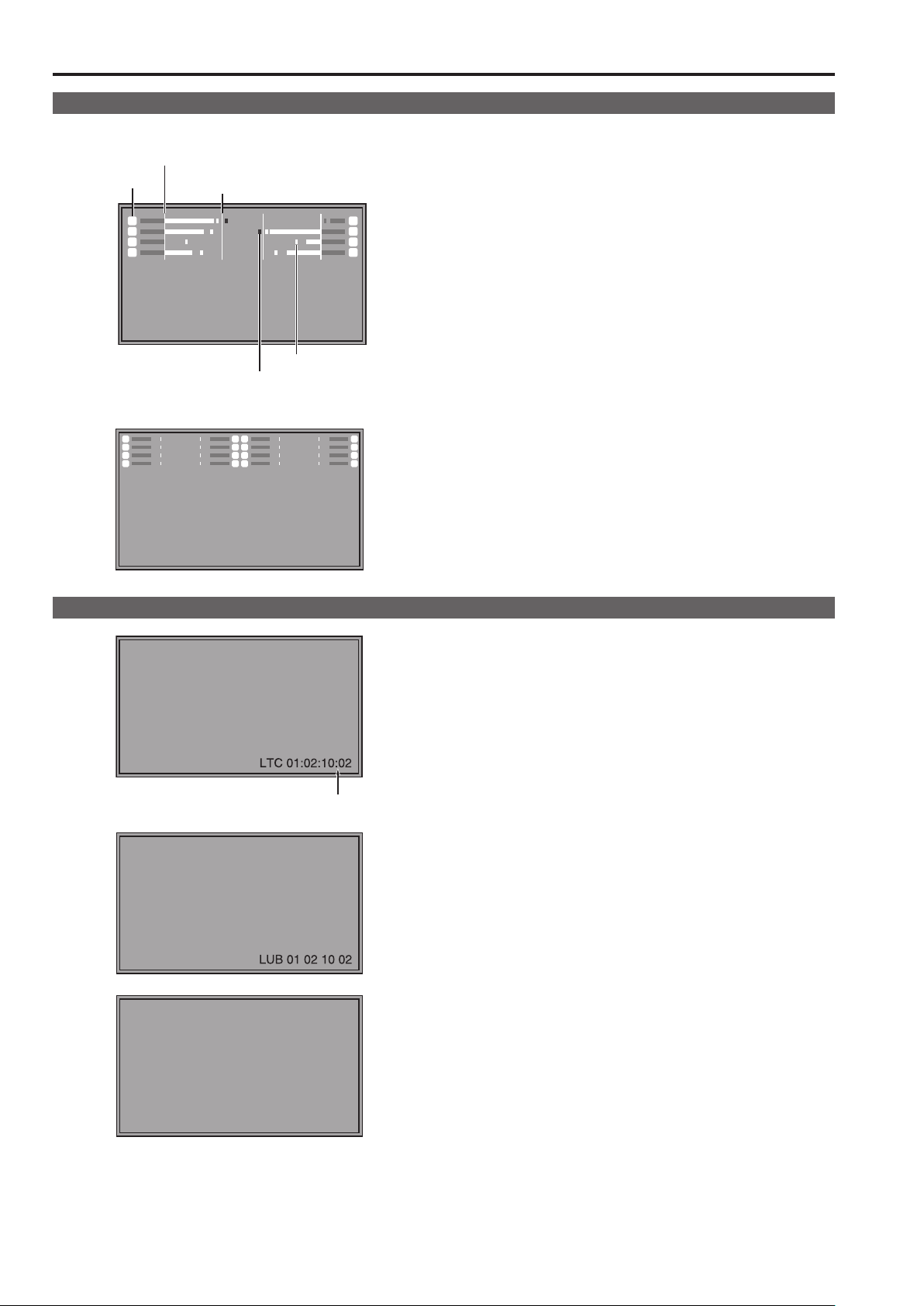
Audio volume bar meter display
● Normal operating mode
Reference point
Channel display
11
33
55
77
SDI1 1080/60i
● In TWO WINDOW mode
11
33
55
77
0 dB point
Overrange
22
11
33
44
55
66
77
88
Peak hold
• A color bar meter indicates the audio level for SDI, HDMI and
AUDIO signals.
• The display method of the audio volume bar meter can be set
in the menu.(→page 45)
• In 3D assist mode, you can monitor the left (L) channel of
22
44
66
88
SDI1 audio.
• In TWO WINDOW mode, it will display SDI1 and SDI2 in
separate windows.
Display color
Green: Up to reference point (included)
Yellow: Reference point (not included) to 0 dB point (not in-
cluded)
Red: Overrange
22
44
66
88
Time code (TC) display
( : ) NDF
( . ) DF
• Use the menu to display the time code for HD-SDI signal
input. It also allows you to switch between display modes:
([LTC], [VITC], [LUB], [VUB], [LTC+LUB], [VITC+VUB]).
(→page 46)
In LTC and VITC display mode
• Displays the time code in: hours: minutes: seconds: or frames.
• In drop-frame mode, a different delimiter is used between
seconds and frames.
<Note>
Read errors are displayed as “--:--:--:--”
In LUB and VUB display modes
• BG8, BG7, BG6, BG5, BG4, BG3, BG2, BG1 appear in the
stated order.
BG: binary group
• The (:) delimiter does not appear.
<Note>
Read errors are displayed as “-- -- -- --”
In LTC+LUB and VITC+VUB display modes
Each combination is displayed separately.
18
LTC 01:02:10:02
LUB
AB CD EF
01
On-screen Display (continued)
Closed caption (CC) display
Closed caption
display area
(When the specified window extends beyond the entire screen)
• This unit can display closed captions with an SDI or VIDEO
signal input.
• Closed captions comply with the following standards.
• Composite Standard EIA/CEA-608 (VBI), OP-42
• SD-SDI CC Standard EIA/CEA-608 (ANC/VBI), OP-42
• HD-SDI CC Standard EIA/CEA-608 (708),
EIA/CEA-708, OP-47
• The EIA/CEA-708 Standard allows simultaneous display of
closed captions at a specified location on up to eight windows.
• Closed captions are displayed on an area inside the screen
that is smaller than the entire screen.
(Refer to the following notes.)
• The display settings can be configured in the menus. The
menu also allow you to select closed caption type, display
channel (EIA/CEA-608) and display service (EIA/CEA-708).
(→page 46)
<Note>
• The specified window position is displayed at a position in the
display area according to the closed caption information.
• The window may extend beyond the display area depending
on the position and size of the specified window. Such a window will be displayed but a window that extends beyond the
entire screen will be repositioned inside the screen area.
IMD (in monitor display) display
● Normal operating mode
CAM1
Tally 1 Tally 2Text
● In TWO WINDOW mode
CAM1 CAM2
• This monitor supports the TSL UMD PROTOCOL (Ver. 3.1
and Ver. 4.0) and allows you to display text and the tally indication on the monitor using the RS-485 interface.
• For information on how to set IMD and communications, refer
to pages 47, 48, 63.
• In TWO WINDOW mode, it will display SDI1 and SDI2 in
separate in monitor display (IMD) windows.
19

21
How to Use the On Screen Menu
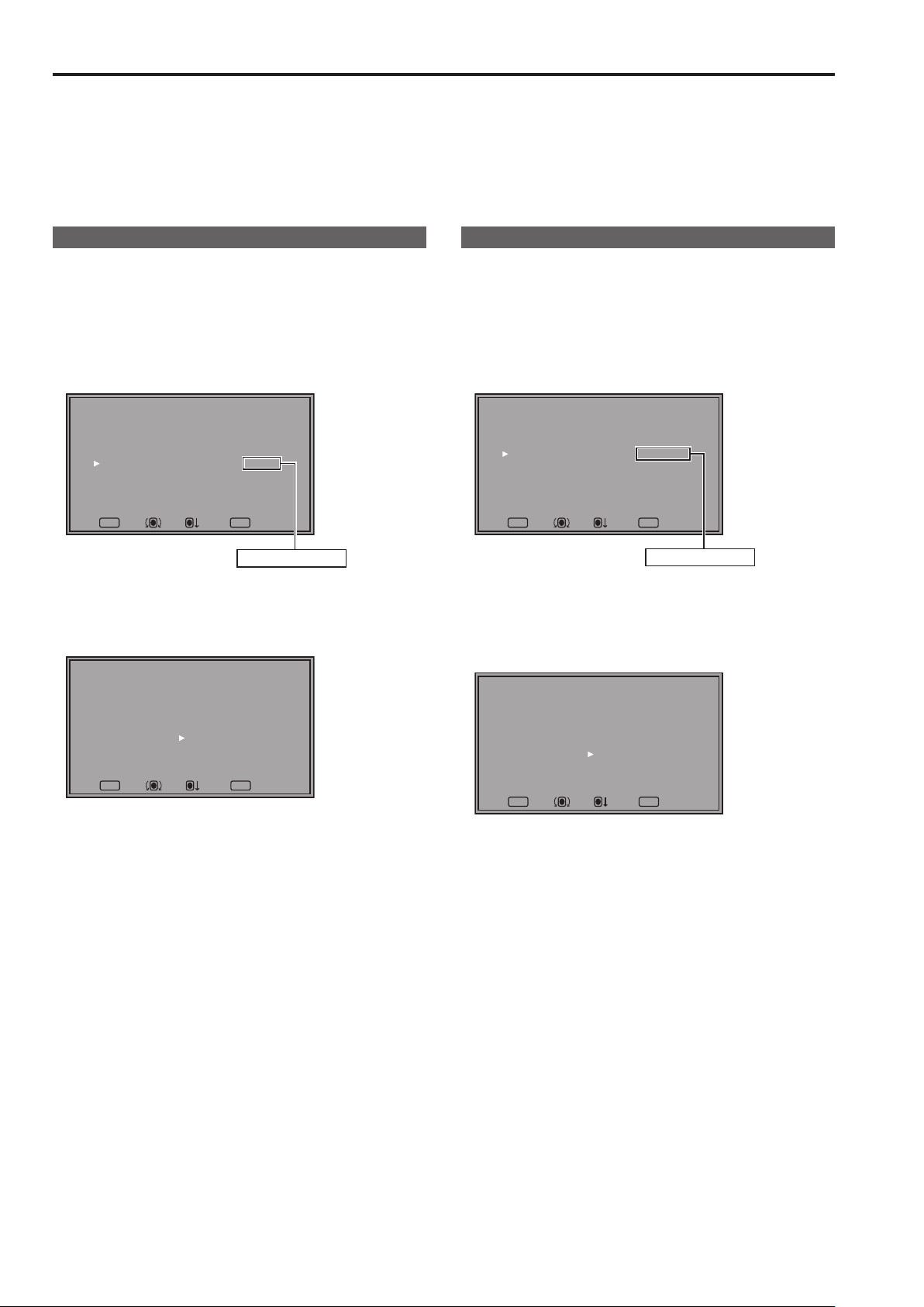
Main menu (MAIN MENU)
• For details on how to open the main menu, refer to “Main
menu (MAIN MENU)/FUNCTION menu/INPUT SELECT menu
displays” (→page16).
1. Turn the rotary knob <PICTURE> to select a menu item
and press the rotary knob <PICTURE>.
[MAIN MENU]
2D/3D ASSIST
MARKER
VIDEO CONFIG
SYSTEM CONFIG
FUNCTION
GPI
INPUT SELECT
AUDIO
DISPLAY SETUP
CONTROL
HOURS METER
MENUEXIT
RETURN
2D
RETURNSEL. ENTER
2. Turn the rotary knob <PICTURE> to select a submenu
item and press the rotary knob <PICTURE>.
• The settings in the submenu change to green.
[MARKER]
MARKER
16:9
4:3
BACK
CENTER
CROSS
COLOR
GPI MARKER1
GPI MARKER2
CROSS HATCH
SIZE
MENUEXIT
OFF
4:3
OFF
NORMAL
OFF
OFF
WHITE
95%(16:9)
95%(16:9)
OFF
LARGE
RETURN
RETURNSEL. ENTER
FUNCTION menu
• For details on how to open the [FUNCTION] menu, refer to
“Main menu (MAIN MENU)/FUNCTION menu/INPUT SELECT
menu displays” (→page16).
1. Turn the rotary knob <PICTURE> to select a function
item.
• Selected function item and set value appear in green.
[FUNCTION]
F1:WFM/VECTOR
F2:TWO WINDOW
F3:FOCUS-IN-RED
F4:TIME CODE
F5:LEVEL METER
WFM/VECTOR OFF
MENUEXIT
RETURN
RETURN
A
2. Press the rotary knob <PICTURE>.
• Each press of the rotary knob <PICTURE> changes the set
value and enables function operation.
[FUNCTION]
F1:WFM/VECTOR
F2:TWO WINDOW
F3:FOCUS-IN-RED
F4:TIME CODE
F5:LEVEL METER
WFM/VECTOR OFF
MENUEXIT
RETURN
RETURN
A
3. To return to the [TOP MENU], press <RETURN/VOLUME>.
3. Turn the rotary knob <PICTURE> to select a set value
and press the rotary knob <PICTURE>.
• To cancel, press <RETURN/VOLUME> before pressing the
rotary knob <PICTURE>.
[MARKER]
MARKER
16:9
4:3
BACK
CENTER
CROSS
COLOR
GPI MARKER1
GPI MARKER2
CROSS HATCH
SIZE
MENUEXIT
95%(16:9)
95%(16:9)
4:3
OFF
NORMAL
OFF
OFF
WHITE
OFF
LARGE
RETURN
RETURNSEL. ENTER
ON
4. To return to the previous screen, press <RETURN/VOL-
UME>.
INPUT SELECT menu
• For details on how to open the [INPUT SELECT] menu, refer
to “Main menu (MAIN MENU)/FUNCTION menu/INPUT SELECT menu displays” (→page16).
1. Turn the rotary knob <PICTURE> to select an input signal
terminal or [INT-SG] and press the rotary knob <PICTURE>.
• To cancel, press<RETURN/VOLUME> before pressing the
rotary knob <PICTURE>.
[INPUT SELECT]
VIDEO
SDI1
SDI2
HDMI
DVI-I
INT-SG
MENUEXIT
RETURN
RETURN
VIDEO : Video input
SDI1 : Serial digital interface input
SDI2 : Serial digital interface input
HDMI : HDMI input
1
DVI-I
: DVI-I input
*
INT-SG
2
: Internal chart for adjustment ([Color Bar +
*
Grayscale]) (→page 77)
The name of the DVI-I input terminal is fixed at [DVI-I].
*1
[INPUT NAME SETUP] in the [SYSTEM CONFIG] menu
cannot be used to change names.
It is not possible to switch to [INT-SG] when two screens are
*2
displayed with the SUB WINDOW function(→page 38).
2. To return to the [TOP MENU], press <RETURN/VOLUME>.
20
How to Use the On Screen Menu (continued)
Picture adjusting (PICTURE) menu
1.
Turn the rotary knob <PICTURE> to select a menu item
and press the rotary knob <PICTURE>.
• The menu closes and the set values of the selected menu
items appear.
[PICTURE]
SETTING[FACTORY]
PEAKING
PHASE
CHROMA
BRIGHT
CONTRAST
BACKLIGHT
F-IN-R
MENUEXIT
[PHASE] 30
RETURN
MENUEXIT
Name Function
PEAKING PEAKING 0 to 30 (0)
PHASE PHASE 0 to 60 (30)
CHROMA CHROMA 0 to 60 (30)
BRIGHT BRIGHT 0 to 60 (30)
CONTRAST CONTRAST 0 to 60 (50)
BACKLIGHT BACKLIGHT 0 to 100 (80)
F-IN-R FOCUS-IN-RED 1 to 30 (15)
The text color of set values that are factory defaults is green
and other values are white.
Settings are loaded when the monitor is turned on. However,
operations and changes cannot be made in the following
conditions.
• When the control lock is on, the
set values cannot be changed. (→page 48)
• When the [MONO] (→page 28) is set to [ON], [PHASE] and
[CHROMA] operations are disabled.
• [F-IN-R] is enabled during operation of the FOCUS-IN-
RED function.
• [BRIGHT] operation is disabled during [HV DELAY]
(→page 34) operation (when it is in any other setting than
OFF).
• [CONTRAST] and [BACKLIGHT] operations are disabled
in [BLACK MODE] (→page 34).
0
30
30
30
50
80
15
RETURN
Adjustable range
( ): denotes factory
mark appears and
defaults.
2. Turn the rotary knob <PICTURE> to select a set value
and press the rotary knob <PICTURE>.
• The set value is confirmed and the menu reappears.
• To cancel, press <RETURN/VOLUME> before pressing the
rotary knob <PICTURE>.
[PHASE] 20
RETURN
MENUEXIT
[PICTURE]
SETTING[FACTORY]
PEAKING
PHASE
CHROMA
BRIGHT
CONTRAST
BACKLIGHT
F-IN-R
MENUEXIT
RETURN
20
30
30
50
80
15
0
*
• When picture adjustments ([PEAKING]/[PHASE]/[CHROMA]/[BRIGHT]/[CONTRAST]/[BACKLIGHT]) have been
changed from the values assigned using [SETUP LOAD] or
[POWER ON SETUP], an asterisk (
menu name.
) appears to right of the
*
Audio volume
• For details on how to use the audio volume, refer to“Audio
volume display” (→page17).
1. Turn the rotary knob <PICTURE> to select a set value.
[VOLUME] 30
MENUEXIT
• Set values are confirmed when they are changed.
• Changing the audio volume when audio output is muted
(“AUDIO MUTE” (→page 35)) immediately cancels [AUDIO
MUTE].
•
is displayed when audio output of the monitor is muted.
• Audio volume is always available and is not affected by the
[CONTROL] menu (→page 48).
• The adjustment range is 0 to 60 (the factory default is 0)
23
User Data
This monitor can save up to five combinations of set values for MAIN MENU and screen adjustments made in the [PICTURE] (picture
adjusting) menu as user data that can be recalled.
You can also return set values and adjustments to their factory defaults.
User data include the following settings.
• Menu settings except [SETUP LOAD], [SETUP SAVE] and [REMOTE] in [CONTROL] (including button function settings on the
monitor front panel)
• Screen adjustments made with the rotary knob <PICTURE>
Saving user data
1.
Press <MENU> to display the main menu.
2. Turn the rotary knob <PICTURE> to select the [SYSTEM
CONFIG] menu and press the rotary knob <PICTURE>.
3. Turn the rotary knob <PICTURE> to select the [SETUP
SAVE] submenu and press the rotary knob <PICTURE>.
The set values in the submenu change to green.
[SYSTEM CONFIG]
SUB WINDOW
MENU POSITION
STATUS DISPLAY
INPUT NAME SETUP
SETUP LOAD
SETUP SAVE
POWER ON SETUP
COLOR SPACE
POWER DOWN
POWER SAVE MODE
CALIBRATION
MENUEXIT
FULL
CENTER
3SEC OFF
FACTORY
USER1
LAST
EBU
OFF
OFF
RETURN
RETURNSEL. ENTER
Changes to green
4. Turn the rotary knob <PICTURE> to select settings to
save from the [USER1] to [USER5] and press the rotary
knob <PICTURE>.
The following screen appears.
[SETUP SAVE]
USER1
YES
NO
Loading user data
1.
Press <MENU> to display the main menu.
2. Turn the rotary knob <PICTURE> to select the [SYSTEM
CONFIG] menu and press the rotary knob <PICTURE>.
3. Turn the rotary knob <PICTURE> to select the [SETUP
LOAD] submenu and press the rotary knob <PICTURE>.
The set values in the submenu change to green.
[SYSTEM CONFIG]
SUB WINDOW
MENU POSITION
STATUS DISPLAY
INPUT NAME SETUP
SETUP LOAD
SETUP SAVE
POWER ON SETUP
COLOR SPACE
POWER DOWN
POWER SAVE MODE
CALIBRATION
MENUEXIT
FULL
CENTER
3SEC OFF
FACTORY
USER1
LAST
EBU
OFF
OFF
RETURN
RETURNSEL. ENTER
Changes to green
4. Turn the rotary knob <PICTURE> to select settings to call
from the [USER1] to [USER5] and press the rotary knob
<PICTURE>.
The following screen appears.
• To return to the factory defaults, select [FACTORY].
[SETUP LOAD]
USER1
YES
NO
MENUEXIT
RETURN
RETURNSEL. ENTER
5. Select [YES] and press the rotary knob <PICTURE>.
This saves the user data.
6. To return to the previous screen, press <RETURN/VOL-
UME>.
MENUEXIT
RETURN
RETURNSEL. ENTER
5. Select [YES] and press the rotary knob <PICTURE>.
This loads the user data.
6. To return to the previous screen, press <RETURN/VOL-
UME>.
22
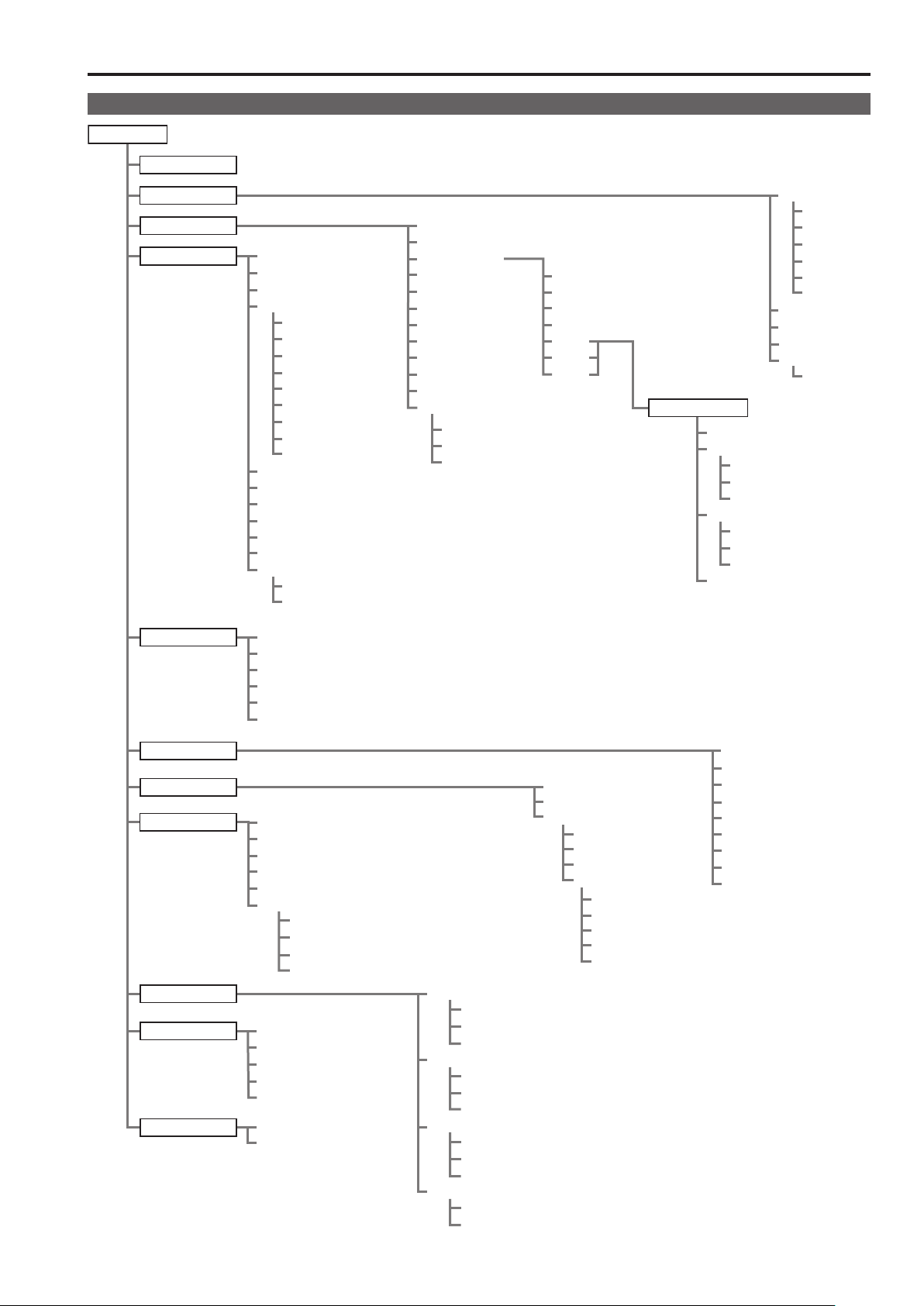
Main Menu
CROSS HATCH
Menu configuration
MAIN MENU
2D/3D ASSIST
MARKER
VIDEO CONFIG
SYSTEM CONFIG
FUNCTION
SUB WINDOW
MENU POSITION
STATUS DISPLAY
INPUT NAME SETUP
VIDEO
SDI1
SDI2
HDMI
BPR
YP
RGB-COMP.
DVI-VIDEO
DVI-COMP.
INT-SG
SETUP LOAD
SETUP SAVE
POWER ON SETUP
COLOR SPACE
POWER DOWN
POWER SAVE MODE
CALIBRATION
AUTO CALIBRATION
RESET
FUNCTION1
FUNCTION2
FUNCTION3
FUNCTION4
FUNCTION5
FUNCTION DISPLAY
GAMMA SELECT
FILM GAMMA
COLOR TEMP.
SHARPNESS MODE
SHARPNESS H
SHARPNESS V
I-P MODE
MONO
ANAMO
SD ASPECT
SCAN
ZEBRA INT.MIN.
INT. MAX.
EXT. MIN.
EXT. MAX.
USER0 to 63
D93
D65
D56
VAR1
VAR2
VAR3
WHITE BALANCE
COLOR TEMP.
GAIN
RED
GREEN
BLUE
BIAS
RED
GREEN
BLUE
RESET
MARKER
16:9
4:3
BACK
CENTER
CROSS
COLOR
GPI MARKER1
GPI MARKER2
MARKER TYPE
SIZE
GPI
INPUT SELECT
AUDIO
DISPLAY SETUP
CONTROL
HOURS METER
INPUT SELECT
GROUP SELECT
SELECT L
SELECT R
SPEAKER OUT
LEVEL METER
CH SELECT
POINT LINE
CH INFO.
HEAD ROOM
CONTROL
LOCAL ENABLE
PROTOCOL VER.
RS-485 ID SETUP
RS-485 STX&ETX
OPERATION
LCD
VIDEO
NTSC SETUP
DVI-I
DIGITAL
ANALOG
COMPONENT LEVEL
RGB-COMP.
H POSITION
V POSITION
PHASE
CLOCK
RESET
WFM/VECTOR
POSITION
VECTOR MODE
VECTOR SCALE
TIME CODE
POSITION
FONT SIZE
MODE SELECT
CLOSED CAPTION
CC TYPE
CAPTION CHANNEL
CAPTION SERVICE
IN MONITOR DISPLAY
POSITION
CHAR. COLOR
GPI CONTROL
GPI1
GPI2
GPI3
GPI4
GPI5
GPI6
GPI7
GPI8
23
Main Menu (continued)
25
2D/3D ASSIST
Setting Description
2D
3D ASSIST
MARKER
Submenu Setting Description
MARKER
16:9
4:3
*2*
BACK
*2*
3
4
2
*
OFF
ON
OFF
4:3
13:9
14:9
CNSCO 2.39
CNSCO 2.35
2:1
VISTA
95%
93%
90%
88%
80%
USER 85%
VAR. H. 85% V. 85%
OFF
95%
93%
90%
88%
80%
USER 85%
VAR. H. 85% V. 85%
NORMAL
HALF
BLACK
Switches between 2D mode and 3D assist mode.
[2D] Operates in 2D mode.
[3D ASSIST] Operates in 3D assist mode.
When you switch to [3D ASSIST], the input line selection will be force switched to
SDI1 or SDI2.
1
*
Selects whether to enable or disable the marker setting.
Selects/displays various markers in 16:9 aspect ratio.
[OFF] No marker display
[4:3] 4:3 marker
[13:9] 13:9 marker
[14:9] 14:9 marker
[CNSCO 2.39] 2.39:1 marker
[CNSCO 2.35] 2.35:1 marker
[2:1] 2:1 marker
[VISTA] VISTA marker
[95%] 95 % area marker
[93%] 93.1 % area marker (TYPE1)
93 % area marker (TYPE2)
[90%] 90 % area marker
[88%] 89.5 % area marker (TYPE1)
88 % area marker (TYPE2)
[80%] 80 % area marker
[USER] An area marker that is adjustable in 1% increments within a range
of 80 to 100%. However, when the [MARKER TYPE] is [TYPE1],
88% and 93% indicate area markers whose height area 89.5% and
93.1%, respectively.
(The factory default is 85 %.)
[VAR.] This area marker can be varied in 1% increments in the range
between 80 to 100% separately for vertical and horizontal.
(The factory default is 85% for both vertical and horizontal)
Selects/displays the marker type for when the angle of view of the displayed
image is 4:3.
[OFF] No marker display
[95%] 95 % area marker
[93%] 93 % area marker
[90%] 90 % area marker
[88%] 89 % area marker (TYPE1)
88 % area marker (TYPE2)
[80%] 80 % area marker
[USER] An area marker that is adjustable in 1% increments within a range
of 80 to 100%. However, when the [MARKER TYPE] is [TYPE1], 88
% indicates an area marker whose height is 89%.
(The factory default is 85 %.)
[VAR.] This area marker can be varied in 1% increments in the range
between 80 to 100% separately for vertical and horizontal.
(The factory default is 85% for both vertical and horizontal)
Selects the background brightness around the marker.
[NORMAL] Normal background
[HALF] 50% signal level
[BLACK] 0 % signal level (black)
Underlined values indicate factory defaults.
Underlined values indicate factory defaults.
This setting is turned [ON] when receiving marker control signals in REMOTE operation. (GPI if set, has priority.)
*1
These settings are disabled when the GPI (→page 60) function is used to control the marker setting.
*2
These settings are enabled only for HD and SD signal input when [SD ASPECT] is set to [16:9] aspect ratio mode. (→ 28 page “SD
*3
ASPECT”)
These settings are enabled only for SD signal input when [SD ASPECT] is set to [4:3] aspect ratio mode. (→ 28 page “SD ASPECT”)
*4
24
 Loading...