


 Loading...
Operating Instructions
Network Camera Indoor Use Only
Model No. BB-HCM381
BB-HCE481
(AC Adaptor Type)
(PoE Type)
Please read this manual before using, and save this manual for future reference.

Operating Instructions
Main Features
This manual is for both BB-HCM381 (AC Adaptor Type) and BB-HCE481 (PoE Type). Available features and operations are different in part depending on the model. Read this manual carefully and use the Network Camera properly.
IPv6*1 Network Camera
Your Panasonic Network Camera supports IPv6 (Internet Protocol Version 6). IPv6 was created to address the additional IP addresses that will be needed as the Internet continues to expand. Since the camera also supports the currently used IPv4, its "dual stack" design will seamlessly operate while IPv6 is phased in. For more information regarding IPv6, see page 21, or visit http://www.ipv6.org/.
PoE (Power over Ethernet) Supported*2 (For Only BB-HCE481 [PoE Type])
The camera supports PoE (Power over Ethernet), and be powered up by using an Ethernet cable without the AC adaptor.
Audio 2-way Communication*3 (Walkie-talkie Type)
2-way audio communication is now possible between your Network Camera and
PC. By connecting a user-supplied microphone and speaker*4 to both the camera and to the PC, you will be able to speak to and hear anyone within range of the camera.
For example, the camera can be used in the following various locations:
•In the baby's room, to hear if the baby is crying.
•At the front door, to see and hear who is at the door.
•In the children's play room, to see and hear if they are safe.
Note
•PLEASE NOTE that under certain circumstances, audio/video recording may be PROHIBITED by law. This device should be used only in compliance with all applicable federal, state and local statutes.
*1 To connect using IPv6, subscribe to your ISP's "IPv4/IPv6 Dual-Stack" or "IPv6 over IPv4 Tunneling" service. The camera does not function on IPv6-only networks.
*2 BB-HCE481 works with a PoE hub only. No port for AC adaptor.
*3 The audio feature does not work well on mobile phones. The Talk button and Listen button cannot be used simultaneously. Depending on the network environment and traffic conditions, the audio may be delayed or may break up.
*4 The speaker connected to the camera requires a built-in amplifier.
2

Operating Instructions
Motion Detection
The camera has a Motion Detection feature that detects movement, such as people, based on the preset threshold and sensitivity of the camera.
You can buffer the camera images, transfer images to an FTP server or send E- mails using the Motion Detection function as a trigger.
Better Image Quality
The CCD sensor and the color night view mode provides better image quality and low light performance.
•The CCD sensor gives you clear image.
•You can monitor live video (Motion JPEG) that refreshes its image 30 frames per second.
•Color night view mode allows you to monitor the camera in low illuminance.
Remote Pan/Tilt/Zoom/Focus
The following features allow you to operate Network Camera from web browser on your PC. High speed Pan/Tilt operation can move the lens horizontally from -175° to +175° and vertically from -120° to 0° in mounting on the table and from 0° to +90° in mounting on the ceiling. This movable lens allows you to view a wide range of perspective from a distant place. Network Camera has a 42x magnifying capacity: a 21x optical zoom and a 2x digital zoom. Automatic and Manual Focusing features provide you with detailed and distinct images. Additionally, the following control features are available to easily and quickly monitor the camera.
Click to Center ........ |
When you click a certain point on the camera image, the |
|
camera moves to display that point in the center of the |
|
image. |
Preset Position ........ |
You can register 20 preset positions. When you select a |
|
preset position, the camera moves to that position. |
Output Control ........ |
You can control external devices (Open or Short to |
|
GND) (E.g., turning a light on or ringing a buzzer). |
Video Output (For Only BB-HCE481)
Network Camera has an analog composite output terminal. You can view images from Network Camera on TV and record them on videotapes. The camera uses the NTSC system for its video output signals. Use an NTSC-compatible TV.
SD Memory Card*1 Recording
The camera has an SD memory card slot. You can record camera images to the SD memory card. If you enable alarm buffer/transfer, you can record the image at the timing of signal detection of door sensor or light. If you enable 1-minute interval timer buffer/transfer to 1 GB SD memory card, you can record about 58,000 images (320 x 240 resolution and standard quality) for about 41 days.
*1 The camera supports 2 GB, 1 GB, 512 MB, 256 MB, 128 MB or 64 MB Panasonic SD memory card (customer-provided).
3

Operating Instructions
Enhanced Multi-Camera Page
The Multi-Camera page displays the moving images from up to 4 cameras, while supporting audio 2-way communication with each. This camera allows you to switch between 3 sets of 4 cameras. Additionally, static images from a maximum of 12 cameras can be displayed on a single page.
DynamicDNS Service Support
DynamicDNS service allows you to access the camera over the Internet with a domain name of your choice (e.g. bob.viewnetcam.com) instead of a global IP address.
Multi-Language Display
The Top page, Single Camera and Multi-Camera page can be displayed in English, French, German, Italian, Spanish, Russian, Simplified Chinese, Korean or Japanese. The Setup, Maintenance and Support pages are displayed only in Simplified Chinese, English or Japanese.
Abbreviations
•UPnP is the abbreviation for Universal Plug and Play.
•"Network Camera" is called "Camera" in this manual.
•"Setup CD-ROM" is called "CD-ROM" in this manual.
Trademarks
•Adobe, Acrobat and Reader are either registered trademarks or trademarks of Adobe Systems Incorporated in the United States and/or other countries.
•Microsoft, Windows, Hotmail and ActiveX are either registered trademarks or trademarks of Microsoft Corporation in the United States and/or other countries.
•SD mark is a trademark of the SD Card Association.
•This software is based in part on the work of the Independent JPEG Group.
•Screen shots reprinted with permission from Microsoft Corporation.
•All other trademarks identified herein are the property of their respective owners.
4

Operating Instructions
Precaution
Information on Disposal for Users of Waste Electrical & Electronic Equipment (private households)
This symbol on the products and/or accompanying documents
means that used electrical and electronic products should not be mixed with general household waste.
For proper treatment, recovery and recycling, please take these
products to designated collection points, where they will be accepted on a free of charge basis. Alternatively, in some countries you may be able to return your products to your local retailer upon the purchase of an equivalent new product.
Disposing of this product correctly will help to save valuable resources and prevent any potential negative effects on human health and the environment which could otherwise arise from inappropriate waste handling. Please contact your local authority for further details of your nearest designated collection point.
Penalties may be applicable for incorrect disposal of this waste, in accordance with national legislation.
For business users in the European Union
If you wish to discard electrical and electronic equipment, please contact your dealer or supplier for further information.
Information on Disposal in other Countries outside the European Union
This symbol is only valid in the European Union.
If you wish to discard this product, please contact your local authorities or dealer and ask for the correct method of disposal.
5

Operating Instructions
Informations relatives à l’évacuation des déchets, destinées aux utilisateurs d’appareils électriques et électroniques (appareils ménagers domestiques)
Lorsque ce symbole figure sur les produits et/ou les documents
qui les accompagnent, cela signifie que les appareils électriques et électroniques ne doivent pas être jetés avec les ordures ménagères.
Pour que ces produits subissent un traitement, une récupération et un recyclage appropriés, envoyez-les dans les points de collecte désignés, où ils peuvent être déposés
gratuitement. Dans certains pays, il est possible de renvoyer les produits au revendeur local en cas d’achat d’un produit équivalent.
En éliminant correctement ce produit, vous contribuerez à la conservation des ressources vitales et à la prévention des éventuels effets négatifs sur l’environnement et la santé humaine qui pourraient survenir dans le cas contraire.
Afin de connaître le point de collecte le plus proche, veuillez contacter vos autorités locales.
Des sanctions peuvent être appliquées en cas d’élimination incorrecte de ces déchets, conformément à la législation nationale.
Utilisateurs professionnels de l’Union européenne
Pour en savoir plus sur l’élimination des appareils électriques et électroniques, contactez votre revendeur ou fournisseur.
Informations sur l’évacuation des déchets dans les pays ne faisant pas partie de l’Union européenne
Ce symbole n’est reconnu que dans l’Union européenne.
Pour vous débarrasser de ce produit, veuillez contacter les autorités locales ou votre revendeur afin de connaître la procédure d’élimination à suivre.
6

Operating Instructions
Benutzerinformationen zur Entsorgung von elektrischen und elektronischen Geräten (private Haushalte)
Entsprechend der grundlegenden Firmengrundsätzen der
Panasonic-Gruppe wurde ihr Produkt aus hochwertigen Materialien und Komponenten entwickelt und hergestellt, die
recycelbar und wieder verwendbar sind.
Dieses Symbol auf Produkten und/oder begleitenden Dokumenten bedeutet, dass elektrische und elektronische Produkte am Ende ihrer Lebensdauer vom Hausmüll getrennt
entsorgt werden müssen.
Bringen Sie bitte diese Produkte für die Behandlung, Rohstoffrückgewinnung und Recycling zu den eingerichteten kommunalen Sammelstellen bzw. Wertstoffsammelhöfen, die diese Geräte kostenlos entgegennehmen.
Die ordnungsgemäße Entsorgung dieses Produkts dient dem Umweltschutz und verhindert mögliche schädliche Auswirkungen auf Mensch und Umwelt, die sich aus einer unsachgemäßen Handhabung der Geräte am Ende Ihrer Lebensdauer ergeben könnten.
Genauere Informationen zur nächstgelegenen Sammelstelle bzw. Recyclinghof erhalten Sie bei Ihrer Gemeindeverwaltung.
Für Geschäftskunden in der Europäischen Union
Bitte treten Sie mit Ihrem Händler oder Lieferanten in Kontakt, wenn Sie elektrische und elektronische Geräte entsorgen möchten. Er hält weitere Informationen für sie bereit.
Informationen zur Entsorgung in Ländern außerhalb der Europäischen Union
Dieses Symbol ist nur in der Europäischen Union gültig.
7

Operating Instructions
Informazioni per gli utenti sullo smaltimento di apparecchiature elettriche ed elettroniche obsolete (per i nuclei familiari privati)
Questo simbolo sui prodotti e/o sulla documentazione di
accompagnamento significa che i prodotti elettrici ed elettronici usati non devono essere mescolati con i rifiuti domestici
generici.
Per un corretto trattamento, recupero e riciclaggio, portare questi prodotti ai punti di raccolta designati, dove verranno accettati gratuitamente. In alternativa, in alcune nazioni
potrebbe essere possibile restituire i prodotti al rivenditore locale, al momento dell’acquisto di un nuovo prodotto equivalente.
Uno smaltimento corretto di questo prodotto contribuirà a far risparmiare preziose risorse ed evitare potenziali effetti negativi sulla salute umana e sull’ambiente, che potrebbero derivare, altrimenti, da uno smaltimento inappropriato. Per ulteriori dettagli, contattare la propria autorità locale o il punto di raccolta designato più vicino.
In caso di smaltimento errato di questo materiale di scarto, potrebbero venire applicate delle penali, in base alle leggi nazionali.
Per gli utenti aziendali nell’Unione Europea
Qualora si desideri smaltire apparecchiature elettriche ed elettroniche, contattare il rivenditore o il fornitore per ulteriori informazioni.
Informazioni sullo smaltimento in nazioni al di fuori dell’Unione Europea
Questo simbolo è valido solo nell’Unione Europea.
Qualora si desideri smaltire questo prodotto, contattare le autorità locali o il rivenditore e chiedere informazioni sul metodo corretto di smaltimento.
8

Operating Instructions
Información sobre la eliminación para los usuarios de equipos eléctricos y electrónicos usados (particulares)
La aparición de este símbolo en un producto y/o en la
documentación adjunta indica que los productos eléctricos y electrónicos usados no deben mezclarse con la basura doméstica general.
Para que estos productos se sometan a un proceso adecuado de tratamiento, recuperación y reciclaje, llévelos a los puntos de recogida designados, donde los admitirán sin coste alguno.
En algunos países existe también la posibilidad de devolver los productos a su minorista local al comprar un producto nuevo equivalente.
Si desecha el producto correctamente, estará contribuyendo a preservar valiosos recursos y a evitar cualquier posible efecto negativo en la salud de las personas y en el medio ambiente que pudiera producirse debido al tratamiento inadecuado de desechos.
Póngase en contacto con su autoridad local para que le informen detalladamente sobre el punto de recogida designado más cercano. De acuerdo con la legislación nacional, podrían aplicarse multas por la eliminación incorrecta de estos desechos.
Para empresas de la Unión Europea
Si desea desechar equipos eléctricos y electrónicos, póngase en contacto con su distribuidor o proveedor para que le informe detalladamente.
Información sobre la eliminación en otros países no pertenecientes a la Unión Europea
Este símbolo sólo es válido en la Unión Europea.
Si desea desechar este producto, póngase en contacto con las autoridades locales o con su distribuidor para que le informen sobre el método correcto de eliminación.
9

Operating Instructions
10
|
Operating Instructions |
|
Table of Contents |
|
|
1 Camera Monitoring..................................................... |
14 |
|
1.1 |
BB-HCM381 Feature Locations................................................... |
14 |
1.1.1 |
Front View................................................................................................ |
14 |
1.1.2 |
Rear View ................................................................................................ |
15 |
1.1.3 |
Bottom View............................................................................................. |
15 |
1.2 |
BB-HCE481 Feature Locations ................................................... |
16 |
1.2.1 |
Front View................................................................................................ |
16 |
1.2.2 |
Rear View ................................................................................................ |
17 |
1.2.3 |
Bottom View............................................................................................. |
17 |
1.3 |
How to Turn on the Camera......................................................... |
18 |
1.4 |
Accessing the Camera ................................................................ |
19 |
1.4.1 |
To Access the Camera in IPv6................................................................. |
21 |
1.5 |
Viewing the Single Camera page ................................................ |
23 |
1.5.1 |
Displaying the Banner.............................................................................. |
26 |
1.5.2 |
Auto Centering the Image (Click to Center) ............................................. |
27 |
1.5.3 Capturing a Still Image ............................................................................ |
28 |
|
1.5.4 Using the Operation Bar .......................................................................... |
29 |
|
1.5.5 Zooming In and Out ................................................................................. |
32 |
|
1.5.6 Automatic and Manual Focusing.............................................................. |
34 |
|
1.5.7 |
Setting Home Position/Alarm Position/Preset Position ............................ |
36 |
1.6 |
Listening to Camera Audio and Talking through the Camera ...... |
40 |
1.7 |
Viewing the Multi-Camera page................................................... |
42 |
1.8 |
Viewing the Buffered Image page................................................ |
44 |
1.8.1 |
Deleting Buffered Images ........................................................................ |
46 |
1.9 |
Viewing Still Images on Your Mobile Phone ................................ |
47 |
1.9.1 |
Enabling or Disabling the Buffer/Transfer on your Mobile Phone............. |
50 |
2 Using the Camera's Basic Features ......................... |
51 |
|
2.1 |
Setup Page of the Camera .......................................................... |
51 |
2.2 |
Connecting the Camera to Your IPv4 Network ............................ |
54 |
2.3 |
Connecting the Camera to Your IPv6 Network ............................ |
59 |
2.4 |
What is IPsec?............................................................................. |
63 |
2.5 |
Encrypting the Camera Image in Transport Mode ....................... |
66 |
2.6 |
Encrypting the Camera Image in Tunnel Mode ........................... |
69 |
2.7 |
Using UPnP™ (Universal Plug and Play)..................................... |
73 |
11

Operating Instructions
2.7.1Connecting the Camera to a Router that
Supports UPnP™ (IPv4 Only) ................................................................. |
74 |
2.7.2Connecting the Camera to a Router that
|
Does Not Support UPnP™ (IPv4 Only).................................................... |
74 |
2.8 |
Registering with the DynamicDNS Service ................................. |
76 |
2.8.1 |
DynamicDNS Service (IPv4/IPv6) ........................................................... |
81 |
2.9 |
Setting the Date and Time........................................................... |
83 |
2.10 |
Changing Camera Settings ......................................................... |
86 |
2.11 |
Adjusting Audio............................................................................ |
92 |
3 |
Registering Users....................................................... |
94 |
3.1Changing the Authentication Setting and Administrator User
|
Name and Password.................................................................... |
94 |
3.2 |
Logging in to the Camera ............................................................ |
98 |
3.3 |
Creating, Modifying or Deleting General Users ........................... |
99 |
4 Buffering or Transferring Images............................ |
102 |
|
4.1 |
Procedures of Buffering or Transferring Images ........................ |
102 |
4.2 |
Buffering or Transferring Images by Timer................................. |
103 |
4.3 |
Buffering or Transferring Images by Alarm Signal ..................... |
113 |
4.4 |
Buffering or Transferring Images by Motion Detection Signal.... |
125 |
4.5 |
Transferring Camera Images in Transport Mode ....................... |
137 |
4.6 |
Transferring Camera Images in Tunnel Mode............................ |
138 |
4.7 |
Setting the Motion Detection ..................................................... |
139 |
4.8 |
Setting Alarm Log Notification ................................................... |
143 |
4.9 |
Using the SD Memory Card....................................................... |
146 |
4.9.1 Format the SD Memory Card ................................................................ |
148 |
|
4.9.2 Start the SD Memory Recording............................................................ |
149 |
|
4.9.3 Stop the SD Memory Recording ............................................................ |
150 |
|
5 |
Using Other Features ............................................... |
151 |
5.1Changing Initial Settings on the Single Camera page or
|
the Multi-Camera page .............................................................. |
151 |
5.2 |
Configuring Multiple Cameras ................................................... |
154 |
5.3 |
Specifying Operation Time ........................................................ |
156 |
5.4 |
Controlling External Output ....................................................... |
158 |
12

|
Operating Instructions |
|
5.5 |
Changing the Indicator Display.................................................. |
159 |
6 |
Camera Maintenance................................................ |
160 |
6.1 |
Maintenance page ..................................................................... |
160 |
6.1.1 |
Confirming the Status ............................................................................ |
161 |
6.1.2 |
Confirming Session Status .................................................................... |
161 |
6.1.3 |
Confirming Alarm Logs .......................................................................... |
162 |
6.1.4 |
Restarting the Camera .......................................................................... |
163 |
6.1.5 |
Updating the Camera Firmware............................................................. |
164 |
6.1.6 |
Creating the Configuration File .............................................................. |
166 |
6.1.7 |
Loading Settings from a Configuration File............................................ |
167 |
6.1.8 |
Resetting the Camera to Factory Default............................................... |
168 |
6.2 |
Support page............................................................................. |
169 |
6.2.1 |
The Help page ....................................................................................... |
169 |
6.2.2 |
Product Information ............................................................................... |
169 |
6.2.3 |
Support Information ............................................................................... |
169 |
6.3 |
External I/O................................................................................ |
170 |
7 |
Other Information ..................................................... |
172 |
7.1 |
FACTORY DEFAULT RESET Button ......................................... |
172 |
7.2 |
Default Setting List..................................................................... |
173 |
7.3 |
Cleaning .................................................................................... |
184 |
7.4 |
Setting an IP Address on Your PC............................................. |
185 |
7.5 |
Using Setup Program ................................................................ |
186 |
7.6 |
Setting Your PC ......................................................................... |
192 |
7.6.1 |
Setting Proxy Server Settings on a Web Browser ................................. |
192 |
7.6.2 |
Setting UPnP™ to Display Camera Shortcut in My Network Places ..... |
195 |
7.6.3 |
Setting the Internet Temporary File Setting on the Web Browser.......... |
195 |
7.7 |
ASCII Character Table ............................................................... |
196 |
7.8 |
File Size and Number of Buffered Images................................. |
197 |
7.9 |
Number of Images on the SD Memory Card ............................. |
198 |
7.10 |
Specifications ............................................................................ |
199 |
8 |
Index .......................................................................... |
202 |
13

Operating Instructions
1 Camera Monitoring
1.1BB-HCM381 Feature Locations
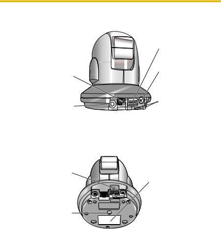
1.1.1Front View

 Auto Focus/Zoom Lens
Wide: 5 mm—Infinity
Tele: 1 m—Infinity
 Indicator
The indicator color shows camera status (see page 159).
 SD Memory Card Cover
Protects the SD Memory Card from dust. Remove the cover only when removing the SD Memory Card (see page 146).
Indicator Display
Power |
Not on LAN |
Orange blinking |
|
|||||||||
on |
On LAN |
Orange blinking |
|
Green blinking |
|
|
Green |
|||||
|
|
|||||||||||
Normal Operation*1 |
|
|
Green |
|
|
|
|
|||||
Automatic |
Setting |
Green blinking |
|
|||||||||
Setup |
|
Finished setting |
Green blinking |
|
|
Green |
|
|||||
|
|
|
||||||||||
Using |
Getting IP address*2 |
Green blinking |
|
|||||||||
DHCP |
|
Got IP address |
|
|
Green |
|
|
|
|
|||
Updating Firmware |
Orange blinking |
|
||||||||||
FACTORY DEFAULT RESET |
Orange blinking |
|
|
Turning off |
|
|||||||
|
|
|
||||||||||
button pressed |
(The camera restarts after that.) |
|
||||||||||
UPnPTM Failure |
Orange blinking (About a 2-second interval) |
|||||||||||
Internal Failure |
Red blinking*3 |
|
||||||||||
*1 The indicator turns orange if the camera is not connected to the LAN. *2 The indicator blinks orange if the camera is not connected to the LAN.
*3 See page 3 and 4 the Troubleshooting on the CD-ROM for information on indicator error codes.
14
Operating Instructions
1.1.2Rear View
Ethernet (LAN) port
Connects the camera to your LAN.
Audio terminal
(See Getting Started)
1.1.3Bottom View
FACTORY DEFAULT RESET button
Resets settings to default (see page 172).
Hole for Ceiling Plate A
Used for ceiling mounting
(See Installation Guide).
External I/O
(See page 170)
DC IN jack
Connects the camera to the AC adaptor.
Hook for AC Adaptor Cord
Used to secure the AC adaptor cord.
MAC Address and Serial Number are indicated on the label.
15

Operating Instructions
1.2BB-HCE481 Feature Locations
1.2.1Front View

 Auto Focus/Zoom Lens
Wide: 5 mm—Infinity
Tele: 1 m—Infinity
 Indicator
The indicator color shows camera status (see page 159).
 SD Memory Card Cover
Protects the SD Memory Card from dust. Remove the cover only when removing the SD Memory Card (see page 146).
Indicator Display
Power |
On LAN |
Orange blinking |
|
|
Green blinking |
|
|
Green |
||||
on |
|
|
|
|
||||||||
|
|
|
|
|
|
|
|
|
|
|
|
|
Normal Operation |
|
|
|
Green |
|
|
|
|
||||
Automatic |
Setting |
Green blinking |
|
|||||||||
Setup |
Finished setting |
Green blinking |
|
|
Green |
|
||||||
|
|
|||||||||||
Using |
Getting IP address*1 |
Green blinking |
|
|||||||||
DHCP |
Got IP address |
|
|
|
Green |
|
|
|
|
|||
Updating Firmware |
Orange blinking |
|
||||||||||
FACTORY DEFAULT |
Orange blinking |
|
|
Turning off |
|
|||||||
|
|
|
||||||||||
RESET button pressed |
(The camera restarts after that.) |
|
||||||||||
UPnPTM Failure |
Orange blinking (About a 2-second interval) |
|||||||||||
Internal Failure |
|
Orange*2 |
|
|
|
|
||||||
|
Red blinking*2 |
|
||||||||||
*1 The indicator blinks orange if the camera is not connected to the LAN.
*2 See page 5 and 6 the Troubleshooting on the CD-ROM for information on indicator error codes.
16

Operating Instructions
1.2.2 |
Rear View |
|
|
|
External I/O |
|
|
(See page 170) |
|
|
PoE IN port |
|
|
Connects the camera |
|
|
to your PoE hub. |
Audio/Video terminal |
|
|
(See Getting Started) |
|
|
1.2.3 |
Bottom View |
|
FACTORY DEFAULT |
|
|
|
RESET button |
|
Resets settings to default |
MAC Address and |
|
|
(see page 172). |
Serial Number are |
|
|
indicated on the label. |
Hole for Ceiling Plate A |
|
|
|
Used for ceiling |
|
|
mounting. |
|
(See Installation Guide) |
|
|
17

Operating Instructions
1.3How to Turn on the Camera
Connecting the AC cord (for BB-HCM381) or the Ethernet cable (for BB-HCE481) turns the camera on, and disconnecting the AC cord (for BB-HCM381) or Ethernet cable (for BB-HCE481) turns the camera off.
BB-HCM381
•Connecting the plug of the AC cord to the outlet turns the camera on.
•Disconnecting the plug of the AC cord from the outlet turns the camera off.
BB-HCE481*1
•Connecting the Ethernet cable to the Ethernet port on the PoE hub turns the camera on.
•Disconnecting the Ethernet cable from the Ethernet port on the PoE hub turns the camera off.
*1 BB-HCE481 does not support the AC adaptor and needs the PoE hub.
18

Operating Instructions
1.4Accessing the Camera
1.Start up the web browser on your PC.
2.Enter "http://IPv4 Address (or URL):Port Number" on the address bar, and press [Enter] on the keyboard.
•When the port number is 80 (default), you do not need to include the port number in the address. See page 56 for details about the port number.
•For IPv6 connection, see page 21 and page 22, and confirm that your equipment meets the requirements.
Enter "http://(IPv6-registered URL):Port Number" on the address bar.
•If the camera image is not displayed, see "Camera Image/Page Display Troubleshooting" on page 9 of the Troubleshooting on the CD-ROM.
E.g. http://192.168.0.253:50000 (in IPv4)
http:// .viewnetcam.com:50000 (in IPv6)
3.The Enter Network Password window is displayed. Enter the user name and password that you set previously, and click [OK].
Note
•When [Permit access from guest users] is set on the Security: Administrator page, the authentication window will not be displayed.
19

Operating Instructions
4.Click the following tabs to display each page.
A B C D E F G
Select a language
Version Number
Displays IPv4, IPv6 or IPsec connection.
A To Single Camera page (page 23)
C To Buffered Image page (page 44)
E To Maintenance page (page 160)
G To log in to the camera (page 98)
Note
B To Multi-Camera page (page 42)
D To Setup page (page 51)
F To Support page (page 169)
•When users other than an administrator are accessing the camera, the [Setup] and [Maintenance] tabs are not displayed. Additionally, when [Do not permit access from guest users] or [Permit access from guest users (mobile only)] is set on the Security: Administrator page, the [Login] tab will not be displayed.
•If [View Multi-Camera page] or [View Buffered Image page] is not permitted on the General User page, the [Multi-Camera] and [Buffered Image] tabs will not be displayed.
5.Close the web browser.
20
Operating Instructions
1.4.1To Access the Camera in IPv6
You need to prepare the following to access the camera in IPv6.
•PC Requirements
Operating System: Windows XP Service Pack 1 or later Web Browser: Internet Explorer 6.0 or later
•An IPv6 Router
•An IPv6 Connection Service
To connect in IPv6, subscribe to the ISP's "IPv4/IPv6 Dual-Stack" or "IPv6 over IPv4 Tunneling" service. The camera does not function on IPv6-only networks.
IPv6 Domain Name Service
In Windows XP, you cannot access the camera by entering its IP address in the web browser. Enter the IPv6 URL that was registered using the domain name service. We recommend the Viewnetcam.com service (see page 76) as a domain name service. Ask your ISP about other IPv6 domain name services.
What is IPv6?
•IPv6 is short for "Internet Protocol Version 6".
•IPv6 was created to provide the additional IP addresses that will be needed as the Internet continues to expand.
•IPv6 is expected to gradually replace IPv4, with the 2 coexisting for a number of years during a transition period.
•Though most ISPs (Internet Service Providers) do not yet support IPv6, many local networks already use it. When your ISP supports IPv6, your Panasonic Network Camera will be ready!
•For more information, visit http://www.ipv6.org/.
Setting up the IPv6 Router, your PC, and the Camera
Setting up the IPv6 Router
Set up the router as you subscribe to the IPv6 service. If access from the WAN side is disabled on the router, enable the TCP packets from the WAN side using packet filtering. See the Panasonic Network Camera support website at http:// panasonic.co.jp/pcc/products/en/netwkcam/ for information about the recommended routers.
21

Operating Instructions
Setting up your PC
1.Click [Start] [All Programs]
 [Accessories]
 [Command Prompt].
•The Command Prompt window is displayed.
2.Enter "ipv6 install".
•"Succeeded" is displayed.
Note
•If Windows XP Service Pack 1 or later is not installed, "Succeeded" will not be displayed. Install it on your PC.
•When you use Windows XP Service Pack 2, click [Start] [Control
Panel] [Security Center]
 [Windows Firewall]
 [Advanced] tab
 [Settings] button of ICMP in the Windows Firewall window, then check [Allow incoming router request] check box in the ICMP Settings window.
3.Enter "ipconfig".
•If the IPv6 address is properly assigned to your PC, IPv6 address will be displayed in the window.
Setting up the Camera
Usually, an IPv6 address is automatically assigned. To assign a static IPv6 address, see page 59. To access the camera in IPv6, you need to subscribe to a domain name service such as Viewnetcam.com, and register the URL.
Confirming that You Can Access the Camera
Confirm that the image is properly displayed (see page 19).
22

Operating Instructions
1.5Viewing the Single Camera page
1.Access the camera (see page 19).
•The Top page is displayed.
2.Click the [Single] tab at the top of the page.
•When the Security Warning window is displayed, click [Yes] (see page 25).
•See page 26 for the Security Warning window when using Microsoft® Windows® XP Service Pack 2.
Capture Image Button
(See page 28)
Operation Bar
(See page 29)
3.Close the web browser.
Note
Audio Control Bar (Talk Button, Listen Button and Adjustment Bar)
(See page 40)
Click to Center
(See page 27)
Click the URL in case of no audio.
Displaying to operate with IPv4, IPv6, or IPsec.
Banner (optional)
(See page 26)
•When the camera image is not displayed immediately or correctly, click [Refresh] on the web browser's tool bar. The image will be refreshed.
•The refresh interval is set to [Motion] by default. The setting can be changed on the operation bar (see page 29).
•The refresh interval may change depending on the network condition, PC performance and what object you view. SD memory recording, using IPsec or enabling Motion Detection will also increase the refresh interval.
23

Operating Instructions
•When displaying video (Motion JPEG), the camera allows up to 30 simultaneous accesses. The 31st user trying to access will see a gray screen. The Buffered Image page is also limited to a maximum of 30 simultaneous accesses.
•To reduce the data traffic, the video can be automatically changed to refreshing still images on the General User page (see page 99).
•To display the Single Camera page directly, add it to the [Favorites] on the web browser.
•To view dark images, enable color night view mode on the Camera Setup page (see page 86). The image will be brighter, but the refresh interval may increase and image quality may decrease in a dark place. (See page 86).
•The following error messages can be displayed.
Error Message |
Cause and Remedy |
|
|
The operation time has |
Images cannot be displayed outside the Operation |
ended. |
Time (see page 156). |
|
|
The maximum number of |
The camera allows a maximum of 30 simultaneous |
accesses has been |
accesses when the Refresh Interval is set to [Motion] |
exceeded. |
and when accessing the Buffered Image page. Users |
|
who try to access the camera when the maximum |
|
number of access has already be reached will see a |
|
gray screen. To view camera images, wait, then click |
|
the Refresh button on your browser. If viewing the |
|
Single Camera page, you can also switch to still |
|
images. |
|
|
24

Operating Instructions
Security Warning window
When trying to view a video (Motion JPEG) for the first time, a Security Warning for
ActiveX® Controls will be displayed. When using Windows 2000 or Windows XP, log in as an administrator to install ActiveX Controls and enable video viewing.
If you cannot install ActiveX Controls or you cannot see the video using the Internet Explorer
•In Internet Explorer, click [Tools] [Internet Options]
 [Security] tab and click [Custom level].
(1)Check "Prompt" in "Download signed ActiveX Controls".
(2)Check "Enable" in "Run ActiveX Controls and plug-ins".
•ActiveX Controls can be installed from the CD-ROM.
(1)Restart the PC.
(2)Confirm that Internet Explorer is closed.
(3)Double-click"ocx\ActiveXInst.exe" on the CD-ROM.
•ActiveX Controls can be downloaded from the Panasonic Network Camera support website at http://panasonic.co.jp/pcc/products/en/netwkcam/.
Note
•When the IP address was changed for the camera, enter it on the address bar.
•Video may not be displayed or audio may not be heard immediately. Wait for a moment.
•If you use a proxy server, set the web browser not to access the proxy server (see page 192).
•In some corporate network environments, a firewall may be used for security purposes. This may prevent motion video from being displayed. In this situation we recommend:
–Contacting your network administrator.
–Using regularly refreshed images rather than video.
25

Operating Instructions
Security Warning window on Microsoft Windows XP Service Pack 2
To view a video (Motion JPEG) or to use audio feature, ActiveX Controls must be installed.
Follow the steps shown below to install ActiveX Controls.
1.Click the warning displayed above the tabs, and click [Install ActiveX Control...].
2.Click [Install].
********
1.5.1Displaying the Banner
An image and its linked website can be specified for a banner. To display the banner, the Banner Display settings need to be set on the Image Display page (see page 151). Clicking the banner displays the website of the set URL Link. The Banner Display is not enabled as the default.
26
Operating Instructions
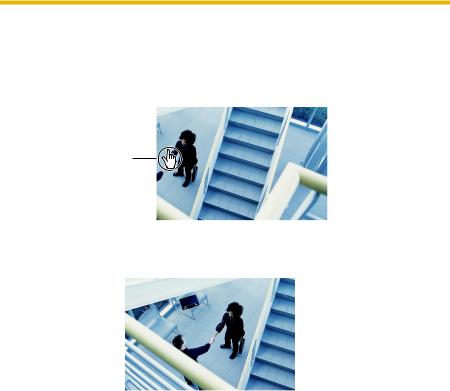
1.5.2Auto Centering the Image (Click to Center)
Using your mouse, click any portion of the camera image. As long as it is within the pan/tilt range of the camera, the image will automatically move to place the selected point in the center of the screen.
1.Move the cursor to the desired point.
Cursor
2.Click it.
•The clicked point is centered.
•See page 31 for the pan/tilt operation.
Note
•When End Display appears on the operation bar, Click to Center does not work beyond the pan/tilt end (see page 29).
•The camera may not center exactly on the clicked point depending on the lens direction.
•If Click to Center is not permitted on the General User page (see page 99), the function will not operate.
27

Operating Instructions
1.5.3Capturing a Still Image
Still images can be saved on your PC.
1.Operate pan/tilt and select a resolution to display an image.
2.Click the capture image button.
Capture Image Button
• The camera image opens in another window.
3.Right-click the image, and select [Save Picture As...].
•The Save as dialog box is displayed.
4.Specify a folder, enter the file name and click [Save].
•The camera image is saved at that location.
5.Click [Close].
28
Operating Instructions
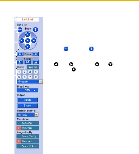
1.5.4Using the Operation Bar
(1) |
|
|
(1) |
End Display and Preset Display: When the pan/tilt |
||||
|
||||||||
|
|
|
|
|
has reached the end of its range, the End Display (Left |
|||
|
|
|
|
|
|
|||
(2) |
|
|
|
|
|
End, Right End, Up End or Down End) appears. When |
||
|
|
|
|
|
the zoom or focus operation has reached the end, Wide |
|||
|
|
|
|
|||||
|
|
|
|
|
|
End, Tele End, Near End, or Far End appears. When you |
||
|
|
|
|
|
|
|||
(3) |
|
|
|
|
|
select a preset, the preset name appears. |
||
|
|
|
|
|
(2) |
Pan Scan/Tilt Scan: Moves the lens throughout the |
||
|
|
|
|
|
||||
|
|
|||||||
|
|
|
|
|
|
horizontal ( ) or vertical ( ) range, and returns to the |
||
|
|
|
|
|
|
|||
(4) |
|
|
|
|
|
original position. |
|
|
|
|
|
|
|
||||
|
|
|
|
|
||||
(5) |
|
|
(3) |
Pan/Tilt/Home Position: Controls lens direction. |
||||
|
||||||||
|
|
|
|
|
Pan ( : Left, |
: Right), Tilt ( : Up, : Down) and |
||
|
|
|
|
|
||||
|
|
|
|
|
|
|||
(6) |
|
|
|
|
|
Home Position ( |
: Center [Default]) |
|
|
|
|
|
|||||
|
|
(4) |
Zoom Buttons: Zooms in or out on the camera |
|||||
|
|
|
|
|||||
|
|
|
|
|
|
image. |
|
|
|
|
|
(5) |
Focus Buttons: Used to adjust the focus. |
||||
|
|
|||||||
|
(6) |
Home Position, Alarm Position, Preset Position: |
||||||
Applies the camera direction to a preset position. You can preset 20 positions (see page 36—page 39).
When the External I/O detects a signal, the camera can be set up to turn to the position of Alarm 1 or Alarm 2. Only an administrator can operate it (see page 36).
29

Operating Instructions
(7) Brightness: Adjusts image brightness in 9 steps including [STD] (Standard). Clicking [-] or [+] changes the image brightness.
(8) Output Control: Controls the output signals of the External I/O.
(9) Refresh Interval: Sets a refresh interval. (Motion—
60-second interval)
(10) Resolution: Selects [640 x 480] or [320 x 240] (default) pixels.
|
|
(11) Image Quality: Selects the image quality. |
|
|
• [Favor Clarity] optimizes the image for good |
|
|
clarity. |
|
|
• [Standard] keeps the standard quality. (default) |
|
|
• [Favor Motion] optimizes the image for motion |
(7) |
|
display. |
|
||
|
|
|
|
|
|
(8)
(9)
(10)
(11)
30
Loading...