


 Loading...
PSG1102001CE
Mechanism Unit
Model No. BRS1C
TABLE OF CONTENTS
PAGE |
|
PAGE |
|
1 Mechanism Overview (BRS1C) ------------------------------ |
2 |
5 Reliability ---------------------------------------------------------- |
29 |
1.1. Mecha Chassis Assembly / Tray / Traverse |
|
5.1. Diagram of Reliability P.C.B. -------------------------- |
29 |
Deck ---------------------------------------------------------- |
2 |
5.2. Functions Descriptions --------------------------------- |
30 |
1.2. Traverse Motor --------------------------------------------- |
3 |
5.3. Ageing MODE Description----------------------------- |
30 |
2 Warning-------------------------------------------------------------- |
4 |
5.4. Reliability Setup Connection -------------------------- |
31 |
2.1. Prevention of Electro Static Discharge (ESD) |
|
5.5. Jig’s Flow Diagram -------------------------------------- |
33 |
to Electrostatically Sensitive (ES) Devices---------- |
4 |
6 Exploded View and Replacement Parts List ----------- |
37 |
2.2. Precaution of Laser Diode------------------------------- |
5 |
6.1. Exploded View and Mechanical replacement |
|
2.3. Service caution based on Legal restrictions -------- |
6 |
Parts List --------------------------------------------------- |
37 |
2.4. Handling Precaution for Traverse Deck-------------- |
7 |
|
|
3 Mechanism Operation ------------------------------------------ |
9 |
|
|
3.1. Close/Open Operation ----------------------------------- |
9 |
|
|
3.2. Open/Close Operation ---------------------------------- |
10 |
|
|
3.3. Initialization------------------------------------------------- |
11 |
|
|
3.4. Fail Safe Mode -------------------------------------------- |
13 |
|
|
4 Disassembly and Assembly Instructions --------------- |
14 |
|
|
4.1. Flow Chart-------------------------------------------------- |
15 |
|
|
4.2. Disassembling Instructions----------------------------- |
16 |
|
|
4.3. Assembly Instructions ----------------------------------- |
21 |
|
|
© Panasonic Corporation 2011. All rights reserved. Unauthorized copying and distribution is a violation of law.
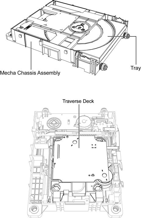
1 Mechanism Overview (BRS1C)
BRS1 mechanism is a single tray mechanism used for CD/DVD models.
1.1.Mecha Chassis Assembly / Tray / Traverse Deck
2

1.2.Traverse Motor
3
2 Warning
2.1.Prevention of Electro Static Discharge (ESD) to Electrostatically Sensi-
tive (ES) Devices
Some semiconductor (solid state) devices can be damaged easily by static electricity. Such components commonly are called Electrostatically Sensitive (ES) Devices. Examples of typical ES devices are integrated circuits and some field-effect transistors and semiconductor “chip” components. The following techniques should be used to help reduce the incidence of component damage caused by electrostatic discharge (ESD).
1.Immediately before handling any semiconductor component or semiconductor-equipped assembly, drain off any ESD on your body by touching a known earth ground. Alternatively, obtain and wear a commercially available discharging ESD wrist strap, which should be removed for potential shock reasons prior to applying power to the unit under test.
2.After removing an electrical assembly equipped with ES devices, place the assembly on a conductive surface such as aluminium foil, to prevent electrostatic charge build up or exposure of the assembly.
3.Use only a grounded-tip soldering iron to solder or unsolder ES devices.
4.Use only an anti-static solder remover device. Some solder removal devices not classified as “anti-static (ESD protected)” can generate electrical charge sufficient to damage ES devices.
5.Do not use freon-propelled chemicals. These can generate electrical charges sufficient to damage ES devices.
6.Do not remove a replacement ES device from its protective package until immediately before you are ready to install it. (Most replacement ES devices are packaged with leads electrically shorted together by conductive foam, aluminium foil or comparable conductive material).
7.Immediately before removing the protective material from the leads of a replacement ES device, touch the protective material to the chassis or circuit assembly into which the device will be installed.
Caution :
Be sure no power is applied to the chassis or circuit, and observe all other safety precautions.
8.Minimize bodily motions when handling unpackaged replacement ES devices. (Otherwise harmless motion such as the brushing together of your clothes fabric or the lifting of your foot from a carpeted floor can generate static electricity (ESD) sufficient to damage an ES device).
4
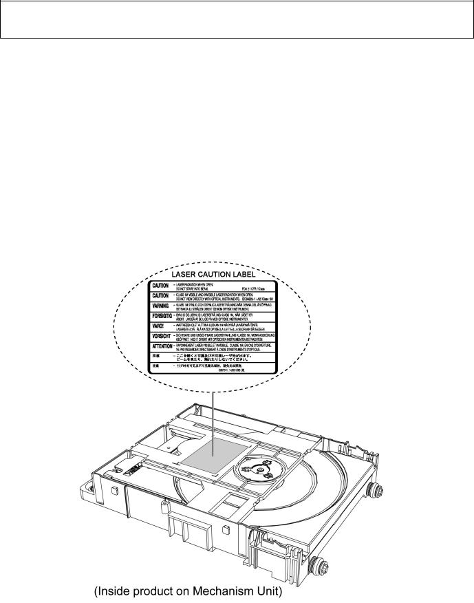
2.2.Precaution of Laser Diode
CAUTION!
THIS PRODUCT UTILIZES A LASER.
USE OF CONTROLS OR ADJUSTMENTS OR PERFORMANCE OF PROCEDURES OTHER THAN THOSE SPECIFIED HEREIN MAY RESULT IN HAZARDOUS RADIATION EXPOSURE.
Caution:
This product utilizes a laser diode with the unit turned "on", invisible laser radiation is emitted from the pickup lens. Wavelength: 655 nm (DVD)/790 nm (CD)
Maximum output radiation power from pickup: 100 μW/VDE
Laser radiation from the pickup unit is safety level, but be sure the followings:
1.Do not disassemble the pickup unit, since radiation from exposed laser diode is dangerous.
2.Do not adjust the variable resistor on the pickup unit. It was already adjusted.
3.Do not look at the focus lens using optical instruments.
4.Recommend not to look at pickup lens for a long time.
ACHTUNG :
Dieses Produkt enthält eine Laserdiode. Im eingeschalteten Zustand wird unsichtbare Laserstrahlung von der Lasereinheitadgestrahit.
Wellenlänge : 655 nm (DVD)/790 nm (CD)
Maximale Strahlungsleistung der Lasereinheit :100 μW/VDE
Die Strahlung an der Lasereinheit ist ungefährlich, wenn folgende Punkte beachtet werden:
1.Die Lasereinheit nicht zerlegen, da die Strahlung an der freigelegten Laserdiode gefährlich ist.
2.Den werkseitig justierten Einstellregler der Lasereinhit nicht verstellen.
3.Nicht mit optischen Instrumenten in die Fokussierlinse blicken.
4.Nicht über längere Zeit in die Fokussierlinse blicken.
5

2.3.Service caution based on Legal restrictions
2.3.1.General description about Lead Free Solder (PbF)
The lead free solder has been used in the mounting process of all electrical components on the printed circuit boards used for this equipment in considering the globally environmental conservation.
The normal solder is the alloy of tin (Sn) and lead (Pb). On the other hand, the lead free solder is the alloy mainly consists of tin (Sn), silver (Ag) and Copper (Cu), and the melting point of the lead free solder is higher approx.30 degrees C (86°F) more than that of the normal solder.
Definition of PCB Lead Free Solder being used
The letter of “PbF” is printed either foil side or components side on the PCB using the lead free solder. (See right figure)
Service caution for repair work using Lead Free Solder (PbF)
•The lead free solder has to be used when repairing the equipment for which the lead free solder is used. (Definition: The letter of “PbF” is printed on the PCB using the lead free solder.)
•To put lead free solder, it should be well molten and mixed with the original lead free solder.
•Remove the remaining lead free solder on the PCB cleanly for soldering of the new IC.
•Since the melting point of the lead free solder is higher than that of the normal lead solder, it takes the longer time to melt the lead free solder.
•Use the soldering iron (more than 70W) equipped with the temperature control after setting the temperature at 350±30 degrees C (662±86°F).
Recommended Lead Free Solder (Service Parts Route.)
•The following 3 types of lead free solder are available through the service parts route. RFKZ03D01K-----------(0.3mm 100g Reel)
RFKZ06D01K-----------(0.6mm 100g Reel) RFKZ10D01K-----------(1.0mm 100g Reel)
Note
* Ingredient: Tin (Sn), 96.5%, Silver (Ag) 3.0%, Copper (Cu) 0.5%, Cobalt (Co) / Germanium (Ge) 0.1 to 0.3%
6
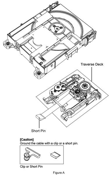
2.4.Handling Precaution for Traverse Deck
The laser diode in the optical pickup unit may break down due to static electricity of clothes or human body. Special care must be taken avoid caution to electrostatic breakdown when servicing and handling the laser diode in the traverse deck.
2.4.1.Cautions to Be Taken in Handling the Optical Pickup Unit
The laser diode in the optical pickup unit may be damaged due to electrostatic discharge generating from clothes or human body. Special care must be taken avoid caution to electrostatic discharge damage when servicing the laser diode.
1.Do not give a considerable shock to the optical pickup unit as it has an extremely high-precise structure.
2.To prevent the laser diode from the electrostatic discharge damage, the flexible cable of the optical pickup unit removed should be short-circuited with a short pin or a clip.
3.The flexible cable may be cut off if an excessive force is applied to it. Use caution when handling the flexible cable.
4.The antistatic FPC is connected to the new optical pickup unit. After replacing the optical pickup unit and connecting the flexible cable, cut off the antistatic FPC.
7

2.4.2.Grounding for electrostatic breakdown prevention
Some devices such as the CD player use the optical pickup (laser diode) and the optical pickup will be damaged by static electricity in the working environment. Proceed servicing works under the working environment where grounding works is completed.
2.4.2.1.Worktable grounding
1. Put a conductive material (sheet) or iron sheet on the area where the optical pickup is placed, and ground the sheet.
2.4.2.2.Human body grounding
1. Use the anti-static wrist strap to discharge the static electricity form your body (Figure 2).
Figure 2
8

3 Mechanism Operation
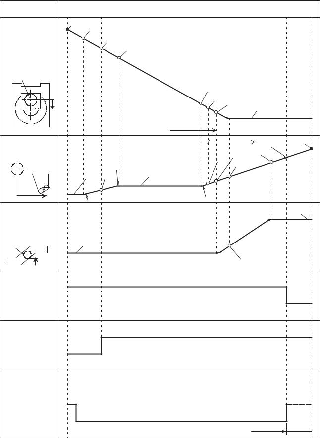
3.1. |
Close/Open Operation |
|
|
|
|
|
||
|
state |
T.S.P. |
Close |
|
|
|
Open |
Tray |
|
stopper |
SW ON |
|
|
|
SW ON |
stopper |
|
|
|
|
|
|
|
|
|
135 |
|
|
|
|
|
|
|
132 |
|
|
|
|
|
|
|
|
129.2 |
|
|
Tray |
|
|
|
|
|
126.9 |
|
|
|
|
|
|
|
|
|
|
|
TT center |
|
|
|
|
|
|
|
|
|
|
|
9.2 |
|
|
|
|
|
|
0 |
2 |
6.9 |
|
|
|
|
|
|
|
|
|
|
|
|
|
|
|
|
|
R8 R4 |
Tray Rack engage |
|
|
|
|
|
55 |
T.S.P. Rack engage |
|
|
|
|
|
TRV Slide Plate |
|
49.9 |
|
|
|
|
|
|
|
TT center |
51.6 |
|
|
33.4 |
31.9 |
R8.45 31.1 |
|
|
|
|
|
|
|
|||
|
|
|
41.7 |
|
|
|
|
30.1 |
|
|
|
38.6 |
R3 |
|
|
R3 |
|
|
|
|
|
|
|
|
||
|
|
7.71 |
R3 |
|
|
|
|
|
|
TRV Base |
|
|
|
|
|
|
|
|
Front boss |
|
|
|
|
0 |
|
|
|
|
|
|
|
|
|
|
|
|
|
|
2.1 |
|
|
|
|
|
|
|
|
R4 |
|
|
|
|
|
|
H |
|
|
|
|
|
|
|
|
Close SW |
|
|
|
|
|
|
|
|
L |
|
|
|
|
|
|
|
|
H |
|
|
|
|
|
|
|
|
Open SW |
|
|
|
|
|
|
|
|
L |
|
|
|
|
|
|
|
|
CW |
|
|
|
|
|
|
|
|
Loading Motor |
|
|
|
|
|
|
|
|
CCW |
|
|
|
|
|
Reverse brake |
|
|
|
|
|
|
|
|
|
|
|
|
|
|
|
|
|
Short brake |
|
|
|
|
|
9 |
|
|
|
|
3.2. |
Open/Close Operation |
|
|
|
|
|||
|
state |
Tray |
Open |
|
|
Close |
T.S.P. |
|
|
stopper |
SW ON |
|
|
SW ON |
stopper |
||
|
|
135 |
132 |
|
|
|
|
|
|
|
|
|
|
|
|
|
|
|
|
|
|
129.2 |
|
|
|
|
|
Tray |
|
|
|
126.9 |
|
|
|
|
|
|
|
|
|
|
|
|
|
TT center |
|
|
|
|
|
|
|
|
|
|
|
|
8.6 |
|
|
|
|
|
|
|
|
6.8 |
2 |
0 |
|
|
|
|
|
|
|
|
|
|
|
|
|
|
|
Tray Rack engage |
|
|
|
|
|
|
|
|
|
T.S.P. Rack engage |
55 |
|
|
|
|
|
|
|
|
51.6 |
|
TRV Slide Plate |
|
|
|
|
|
|
||
|
|
|
33.8 38.6 |
49.9 |
|
|||
|
|
|
|
|
|
|
||
|
TT center |
|
|
R8.45 |
|
41.7 |
|
|
|
|
|
|
31.9 |
|
|
|
|
|
|
|
30.1 |
31.1 |
|
|
|
|
|
|
|
R3 |
|
R3 |
|
|
|
|
|
|
|
|
|
|
|
|
|
|
|
|
|
|
|
7.71 |
|
|
TRV Base |
|
|
|
|
|
|
|
|
Front boss |
|
0 |
|
|
|
|
|
|
|
|
|
|
|
|
|
|
|
|
|
|
|
|
2.1 |
|
|
|
H |
|
|
|
|
|
|
|
|
Close SW |
|
|
|
|
|
|
|
|
L |
|
|
|
|
|
|
|
|
H |
|
|
|
|
|
|
|
|
Open SW |
|
|
|
|
|
|
|
|
L |
|
|
|
|
|
|
|
|
CW |
|
|
|
|
|
|
|
|
Loading Motor |
|
|
|
|
|
|
|
|
CCW |
|
|
|
|
|
|
|
|
|
|
|
|
|
|
Short brake |
|
|
|
|
|
|
10 |
|
|
|
3.3.Initialization
During the power-up of main unit (using BRS1C mechanism), the state of switches is sensored by the micro-p IC and the traverse motor is adjusted accordingly.
Note : Refer to Table 1 for the initialization process.
Condition for Initialization Processing: |
|
|
|||
|
LOAD-SW |
LD-MOTOR |
INNER-SW |
TRV-MOTOR |
|
|
|
|
|
|
|
Condition 1 |
LC |
- |
H |
CCW |
|
LO |
CCW |
H |
CCW |
||
|
|||||
Condition 2 |
LC |
- |
L |
CW |
|
LO |
CCW |
L |
CW |
||
|
|||||
Main Consideration
Table 1
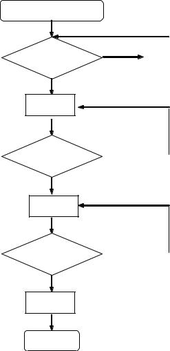
3.3.1.When there is no Initialization
Initialization
Decision Processing
Backup |
N |
INNER-SW= L ? |
Y |
Memory cleared? |
|
LOAD-SW = LC? |
EXIT |
|
|
No need initialization
Y N
Initialization Processing
EXIT
11
3.3.2.When there is Initialization
Initialization Processing
|
N |
|
|
INNER-SW |
TRV-MOTOR |
||
= L ? |
|
CCW |
|
Y
TRV-MOTOR
CW
INNER-SW |
N |
|
|
= H ? |
|
Y
TRV-MOTOR
CCW
INNER-SW |
N |
= L ? |
|
Y
TRV-MOTOR
Brake
EXIT
12
Loading...