


 Loading...
Operating Instructions
<Basics>
Installation Instructions provided
Model No.
Model No.
Model No.
Model No.
4K Integrated Camera
AW UN70WPC AW UN70KPC AW UN70WE AW UN70KE
Instructions
Installation
ENGLISH <Basics>
FRANÇAIS
ESPAÑOL
DEUTSCH
ITALIANO
PУССКИЙ
Before using this product, be sure to read “Read this first!” (pages 5, 27 to 31).
This manual contains information excerpted from the Operating Instructions and the Installation Instructions.
For more information, please visit the Panasonic website (http://pro-av.panasonic.net/manual/en/index.html), and refer to the Operating Instruction (PDF).
Avant d’utiliser cet appareil, assurez-vous de lire la section « Lire ces informations en premier ! ».
Pour de plus amples informations, visiter le site Web de Panasonic (http://pro-av.panasonic.net/manual/en/index. html) et consulter le mode d’emploi (PDF).
Antes de usar este producto, asegúrese de leer “Lea este documento en primer lugar!”.
Si desea obtener más información, visite el sitio web de Panasonic (http://pro-av.panasonic.net/manual/en/index. html) y consulte las instrucciones de funcionamiento (PDF).
Bitte lesen Sie sorgfältig die „Bitte lesen Sie zuerst diesen Hinweis!“ vor der Nutzung dieses Produkts.
Weitere Informationen finden Sie auf der Panasonic-Webseite (http://pro-av.panasonic.net/manual/en/index.html) und in der Bedienungsanleitung (PDF).
Prima di utilizzare il prodotto, assicurarsi di leggere “Leggere prima quanto segue!”.
Per maggiori informazioni, per favore visitare il sito web Panasonic (http://pro-av.panasonic.net/manual/en/index. html), e fare riferimento alle istruzioni per l’uso (PDF).
Перед использованием данного прибора ознакомьтесь с информацией в разделе «Прочитайте
нижеследующее до начала эксплуатации!».
Для получения дополнительной информации посетите веб-сайт Panasonic (http://pro-av.panasonic.net/ manual/en/index.html), а также обратитесь кинструкции по эксплуатации (PDF).
Instructions
Operating
Before operating this product, please read the instructions carefully and save this manual for future use.
CX1217TY0 -FJ |
ENGLISH |
|
Printed in China DVQX1544ZA
български
Hrvatski
Čeština
Dansk
Nederlands
Eesti
Suomi
Ελληνικά
Magyar
Посетете следния уебсайт относно информация за безопасността и важни уведомления за продукта.
Za sigurnosne informacije i važne obavijesti o proizvodu posjetite sljedeću internetsku stranicu.
Na následujícím webu najdete bezpečnostní informace a důležité poznámky k tomuto produktu.
Besøg følgende webside for sikkerhedsinformation og vigtige bemærkninger vedrørende produktet.
Ga naar de volgende website voor veiligheidsinformatie en belangrijke meldingen over het product.
Toodet puudutava ohutusteabe ja oluliste märkuste saamiseks külastage järgmist veebilehte.
Käy seuraavalla verkkosivulla saadaksesi turvallisuustietoja ja tärkeitä tietoja liittyen laitteeseen.
Για πληροφορίες σχετικά με θέματα ασφάλειας και σημαντικές ειδοποιήσεις που αφορούν το προϊόν
σας, επισκεφτείτε τον ιστότοπο που ακολουθεί.
A termékkel kapcsolatos biztonsági információkért és fontos értesítésekért látogasson el az alábbi weboldalra.
Latviešu
Lietuvių
Polski
Português
Română
Slovensky
Slovenščina
Svenska
Lai iegūtu informāciju par drošību un skatītu svarīgus paziņojumus par šo produktu, apmeklējiet tālāk norādīto tīmekļa vietni.
Jei reikia saugos informacijos ir svarbių pranešimų apie gaminį, apsilankykite toliau nurodytoje svetainėje.
Informacje o bezpieczeństwie i ważne informacje o produkcie znajdują się w poniższej witrynie internetowej.
Consulte o seguinte website para as informações de segurança e importantes notificações sobre o produto.
Vizitați următoarea pagină web pentru informaţii de securitate și notificări importante cu privire la produs.
Pre bezpečnostné informácie a dôležité oznámenia súvisiace s produktom navštívte túto webovú stránku.
Za varnostne informacije in pomembna obvestila v zvezi z izdelkom obiščite naslednje spletno mesto.
Besök följande webbplats för säkerhetsinformation och viktiga meddelanden om produkten.
http://pro-av.panasonic.net/manual/en/index.html
2

Trademarks and registered trademarks
●● Microsoft®, Windows®, Windows® 7, Windows® 8, Windows® 8.1, Internet Explorer® and ActiveX® are either registered trademarks or trademarks of Microsoft Corporation in the United States and other countries.
●● Intel® and Intel® CoreTM are trademarks or registered trademarks of Intel Corporation in the United States and other countries.
●● Adobe® and Reader® are either registered trademarks or trademarks of Adobe Systems Incorporated in the United States and/or other countries.
●● HDMI, the HDMI logo and High-Definition Multimedia Interface are the trademarks or registered trademarks of HDMI Licensing LLC in the United States and other countries.
●● microSDXC Logo is a trademark of SD-3C, LLC.
●● Apple, Mac, OS X, iPhone, iPod Touch, iPad, and Safari are registered trademarks of Apple Inc., in the United States and other countries.
●● AndroidTM is a trademark of Google Inc.
●● Other names of companies and products contained in these Operating Instructions may be trademarks or registered trademarks of their respective owners.
About copyright and licence
Distributing, copying, disassembling, reverse compiling, reverse engineering, and also exporting in violation of export laws of the software provided with the unit are expressly prohibited.
This product incorporates the following software:
(1)the software developed independently by or for Panasonic Corporation,
(2)the software owned by third party and licensed to Panasonic Corporation,
(3)the software licensed under the GNU General Public License, Version 2.0 (GPL V2.0),
(4)the software licensed under the GNU LESSER General Public License, Version 2.1 (LGPL V2.1), and/or
(5)open source software other than the software licensed under the GPL V2.0 and/or LGPL V2.1.
The software categorized as (3) - (5) are distributed in the hope that it will be useful, but WITHOUT ANY WARRANTY, without even the implied warranty of MERCHANTABILITY or FITNESS FOR A PARTICULAR PURPOSE.
For details, refer to the license conditions that appear when the operation described on P. 110 of the <Operations and Settings> is performed.
At least three (3) years from delivery of this product, Panasonic will give to any third party who contacts us at the contact information provided below, for a charge no more than our cost of physically performing source code distribution, a complete machine-readable copy of the corresponding source code covered under GPL V2.0 or LGPL V2.1, as well as the respective copyright notice thereof. Contact Information: oss-cd-request@gg.jp.panasonic.com
The source code and the copyright notice are also available for free in our website below.
https://panasonic.net/cns/oss/index.html
Abbreviations
The following abbreviations are used in this manual.
●● Microsoft® Windows® 7 Professional SP1 32/64-bit is abbreviated to “Windows 7”.
●● Microsoft® Windows® 8 Pro 32/64-bit is abbreviated to “Windows 8”.
●● Microsoft® Windows® 8.1 Pro 32/64-bit is abbreviated to “Windows 8.1”.
●● Windows® Internet Explorer® 8.0, Windows® Internet Explorer® 9.0, Windows® Internet Explorer® 10.0 and Windows® Internet Explorer® 11.0 are abbreviated to “Internet Explorer”.
For the purposes of this manual, the model numbers of the units are given as listed in the table below.
Model number |
Model number |
|
of unit |
given in manual |
|
|
|
|
AW UN70WPC, AW UN70KPC, |
AW UN70 |
|
AW UN70WE, AW UN70KE |
||
|
||
|
|
|
AW HS50N |
AW HS50 |
|
|
||
AW HS50E |
||
|
||
|
|
|
AW RP50N |
AW RP50 |
|
|
||
AW RP50E |
||
|
||
|
|
|
AW-RP120G |
AW-RP120 |
|
|
|
|
AK-HRP200G |
AK-HRP200 |
|
|
|
Illustrations and screen displays featured in the manual
●● What is shown in the manual’s illustrations and screen displays may differ from how it is actually appears.
●● The screenshots are used in accordance with the guidelines of Microsoft Corporation.
3
Contents
 Installation Instructions
Read this first! |
|
5 |
Installation precautions |
|
6 |
How to install and connect the unit |
|
8 |
When using the WV Q105A (optional accessory) |
|
12 |
Removing the camera |
|
14 |
Stand-alone installation |
|
|
(when the mount bracket is going to be used) |
|
15 |
Stand-alone installation |
|
|
(when the mount bracket is not going to be |
|
|
used) |
|
17 |
When installing the unit on a desktop |
|
17 |
When mounting the unit on a tripod |
|
17 |
Connections |
|
18 |
Connecting an NDI|HX compatible switcher |
|
18 |
Connecting a controller (AW RP50/AW RP120) |
|
19 |
(IP connection example) |
||
System example 1 (connection with commercially |
|
|
available controller, RS-232C daisy-chain |
|
|
connection) |
|
20 |
System example 2 (connection with commercially |
|
21 |
available controller, RS-422 connection) |
|
|
System example 3 (serial control) |
|
22 |
System example 4 (IP control) |
|
23 |
System example 5 (infrared output connection) |
|
24 |
System example 6 (IP image transmission, PoE+) |
|
24 |
System example 7 (USB connection, Web camera) |
25 |
|
Appearance |
|
26 |
 Operating Instructions
Read this first! (For AW UN70WPC, AW UN70KPC) |
27 |
|
Read this first! (For AW UN70WE, AW UN70KE) |
|
29 |
Before use |
|
32 |
Overview |
|
32 |
Required personal computer environment |
|
32 |
Disclaimer of warranty |
|
33 |
Network security |
|
33 |
Characteristics |
|
34 |
Controller supported |
|
36 |
Accessories |
|
36 |
Optional accessories |
|
36 |
Operating precautions |
|
37 |
Concerning the wireless remote control |
|
|
(optional accessory) |
|
39 |
Parts and their functions |
|
40 |
Camera unit |
|
40 |
Wireless remote controller (optional accessory) |
|
43 |
Setting the remote control IDs |
|
45 |
Network settings [When using Windows] |
|
46 |
Use the Easy IP Setup Software to establish the |
|
46 |
unit’s settings |
||
Installing the plug-in viewer software |
|
47 |
User authentication |
|
48 |
Troubleshooting |
|
49 |
Specifications |
|
51 |
Index |
|
55 |
4

Read this first!
|
|
|
|
|
|
|
|
|
|
|
WARNING: |
|
CAUTION: |
|
|
To prevent injury, this apparatus must be securely |
|
This camera intended for use only with the Mount |
|
|
attached to the floor/wall in accordance with the |
|
Bracket enclosed with the unit and Panasonic Direct |
|
|
installation instructions. |
|
Ceiling Mount Bracket, WV-Q105A. |
|
|
|
|
Use with other apparatus is capable of resulting in |
|
|
|
|
||
|
|
|
instability causing possible injury. |
|
|
WARNING: |
|
|
|
|
|
|
|
|
|
Installation should only be performed by qualified |
|
|
|
|
installation personnel. |
|
|
|
|
Improper installation may result in the entire |
|
|
|
|
apparatus falling down and causing injury. |
|
|
|
|
|
|
|
|
|
|
|
|
|
|
|
|
|
|


 indicates safety information.
Instructions
Installation
5
Installation precautions
Panasonic does not accept any responsibility for accident or damage during installation if procedure in this manual is not followed.
To installation personnel
Read the “Installation Instructions” thoroughly and then perform the operation correctly and safely. Also, always read the “Read this first!” (page 5) of this manual as they contain important information. After the installation, give the “Operating Instructions <Basics>” to the customer to save for future use.
Ensure that the installation work complies with the technical standards governing electrical equipment.
The unit is for indoor use only.
It cannot be used outdoors.
Avoid installation in a location where the unit will be exposed to direct sunlight for extended periods or near a cooling or heating appliance.
Otherwise, deformation, discoloration, malfunctioning and/or problems in operation may result. Operate the unit where it will not be splashed or sprayed by water.
Use the unit with an installation where the unit is suspended from an overhead surface or with a stand alone installation.
Do not use the unit on its side or tilted at an angle.
Notes
●● Be absolutely sure to use the four bracket mounting screws (M4) for mounting the mount bracket. These are supplied with the unit. Do not use wood screws, nails, etc.
In the case of a concrete ceiling, secure the unit using anchor bolts (for M4) or AY plug bolts (for M4).
Recommended clamping torque M4: 1.47 N · m {15 kgf · cm}
●● The withdrawal strength of the mounting location for each screw must be at least 196 N {20 kgf}.
●● When mounting the unit on a ceiling made of plasterboard, for instance, if it is not strong enough to support its weight, either reinforce the ceiling adequately or use the WV Q105A direct ceiling mount bracket, which is sold separately.
●● When using a mount bracket which is sold separately, read the handling instructions.
●● Do not hold the camera head while undertaking the installation work. Doing so may cause malfunctioning.
Concerning the installation location
Install the unit in a stable location which will not be susceptible to shaking. If the unit is installed in a location which is susceptible to shaking, this will cause the unit’s images to shake in turn.
Install the unit after conferring in detail with your dealer. Install the unit on a ceiling that is strong enough (such as a concrete ceiling).
If the unit is to be installed on a ceiling which is not strong enough, reinforce the ceiling sufficiently first.
Do not install or use the unit in the following kinds of locations.
●● On walls (where the unit would be installed sideways)
●● In locations (including places such as under the eaves of a building) where the unit would be directly exposed to rain or water
●● In locations such as kitchens where there are high concentrations of steam and grease
●● In outdoor locations or hot places where the temperature will exceed 40 °C (104 °F)
●● In cold locations where the temperature will drop below 0 °C (32 °F)
●● In locations where the humidity will exceed 90%
●● In locations where chemicals are used such as near swimming pools
●● At sea, in coastal areas or in locations where corrosive gases are emitted
●● In locations where radiation, X-rays, or strong radio waves or magnetic fields are generated
●● In locations where the unit would be subject to a great deal of vibration such as on board a vehicle or ship (the unit is not designed to be used in vehicles)
●● In locations where the temperature is subject to sudden changes such as near the air outlet of an air conditioner or near a door which allows the outside air to come in
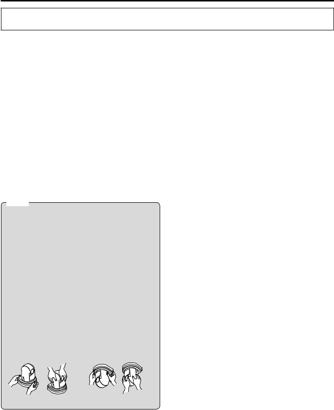
Correct Incorrect Correct Incorrect
Desktop installation |
Hanging installation |
What to avoid to ensure that the unit will perform stably over a prolonged period
●● Using the unit for a prolonged period in a location with high temperature and humidity levels will cause its parts to deteriorate and shorten its service life.
●● Ensure that a cooling unit or heating unit will not blow any air directly toward the installation location.
AW UN70 |
|
|
Mounting conditions |
|
|
|
|
main unit |
Applicable mount bracket |
|
Mounting onto the ceiling |
||||
|
|
|
|
|
|
|
|
Mass |
Model No. |
Mass |
Mounting |
Recommended |
|
No. of |
Minimum withdrawal strength |
screws |
|
screws |
(per screw) |
||||
|
|
|
|
|
|||
|
Direct mount |
Approx. |
|
M4 screws |
|
|
196 N {20 kgf} |
|
(supplied |
0.23 kg |
Hanging/Desktop |
(supplied |
|
4 |
●● Ensure that the mounting strength |
Approx. |
accessory) |
[0.51 lb] |
|
accessory) |
|
|
can support a weight that is at |
1.5 kg [3.30 lb] |
WV Q105A |
Approx. |
|
M4 screws |
|
|
least five times the total mass |
|
(optional |
0.15 kg |
For ceiling |
(supplied with the |
|
4 |
of the equipment, including the |
|
accessory) |
[0.33 lb] |
|
WV Q105A) |
|
|
camera’s main unit. |
|
|
|
|
|
|
|
|
6

Installation precautions (continued)
Be absolutely sure to use the specified brackets and screws to install the camera.
●● Do not mount the unit by employing any methods other than those specified.
●● Do not remodel the mounting bracket or mounting screws provided with the unit.
Before installation, always disconnect the power plug
When installing, always use the supplied components. Do not disassemble or modify the wall mount adaptor.
Tightening up the mounting screws
●● Tighten up the screws and bolts securely to the degree that is appropriate for each of the materials used in the mounting location and structures.
●● After tightening up the screws and bolts, check that there is no unsteadiness and that the parts have been tightened securely.
●● Use the specified tools and tighten the screws firmly. ●● Tighten up the screws using the specified torque driver.
Do not use electrical drivers or impact drivers.
When the unit is no longer going to be used, do not leave it lying around, but be absolutely sure to remove it properly.
For details on how to remove the unit, refer to “Removing the camera” (page 14).
When installing, transferring or disposing of the unit, be absolutely sure to hold it by its pedestal area.
Problems may result if the camera head is held or rotated.
Do not attach a filter, hood, extender or other parts to the unit.
Use the dedicated AC adaptor and power cable provided with the unit.
Connect the AC adaptor and power cable to the power inlet securely.
Installing the AC adaptor
●● Do not place the adaptor directly onto a ceiling panel or other such surface.
Extreme danger is posed when water has collected on the surface as a result of leaking rain, for instance.
Secure the adaptor firmly to the bottom or other surface of a reinforcing member made of channel steel where dust and other foreign matter will not accumulate.
(Refer to page 12.)
●● Secure the adaptor firmly so that there will be no chance that it will fall off or fall down.
Secure it using a strength which can withstand the mass of the AC adaptor.
Install the accessory AC adaptor near the main power outlet, and position it in such a way that its power plug can be plugged into and unplugged from the outlet easily.
When connecting the AC adaptor to a power outlet on the ceiling or on any other surface where dust may collect, wipe off the dust on the power plug at periodic intervals as an antitracking measure.
Power switch
The unit does not have a power switch. The power turns on when its power plug is connected to a power outlet. When the power is turned on, the pan, tilt, zoom and focusing operations are performed. Before proceeding with maintenance, be absolutely sure to disconnect the power plug from the power outlet.
Connecting the power cable
Be absolutely sure to connect the power cable of the AC adaptor through a circuit breaker using one of the following methods.
(1)Connect the power cable through a power control unit.
(2)Connect the power cable to a circuit breaker in a power distribution panel with a contact distance of 3.0 mm (1/8 inches) or more.
Use a circuit breaker which is capable of shutting off all the poles of the main power supply with the exception of the protective ground conductor.
(3)Install the AC adaptor near the power outlet, and connect it through the power plug.
If there is a possibility of noise interference
Either wire the cables so that the power cable (ceiling light cord) of AC 100 V* [AC 220 V**] or more, and the signal cable are placed at least 1 meter (3.3 ft) apart. Alternatively run each cable through its own metal conduit. (The metal conduits must be grounded.)
*: For AW UN70WPC, AW UN70KPC
**: For AW UN70WE, AW UN70KE
Radio signal interference
If the unit is positioned near a TV or radio transmitting antenna or a strong electrical field or magnetic field (such as that generated by a motor, transformer or power lines), its images may be distorted and/or the images may be affected by noise.
When connecting the cables, ensure that the connector areas will not be subject to any load.
Doing so may cause malfunctioning.
Allowing the generated heat to escape
The unit allows the heat generated inside to escape from its surfaces.
Do not install the unit in a location where it will be surrounded by walls or other surfaces and where heat will be trapped. In addition, the heat is dissipated to the bottom panel which will warm up over time: This is normal and not indicative of any trouble.
PoE+ power supplies
Use a PoE+ (IEEE802.3at compliant) compatible hub or power supply device.
Instructions
Installation
7
How to install and connect the unit
Be absolutely sure to read through the “Read this first!” (page 5) and “Installation precautions” (pages 6 to 7).
The procedure given here is for the kind of installation where the unit is suspended from an overhead surface, but the same steps are followed for a stand-alone installation.
If the ceiling panel is not strong enough to bear the unit’s weight, use the kind of mount bracket that is supported by anchor bolts between the concrete ceiling and ceiling panel. The unit supports the WV Q105A direct ceiling mount bracket which is used solely for combination cameras. Use this bracket to install the unit. (See page 12.)
In a case like this, the holes (ø 60 mm [ø 2-3/8 inches]) for installing the direct ceiling mount bracket on the ceiling must be drilled in the ceiling panel.
It is also recommended that you provide an inspection space or opening for access purposes in the area near where the equipment is installed in order to facilitate installation and the wiring connections work.
See page 36 for details of the accessories.
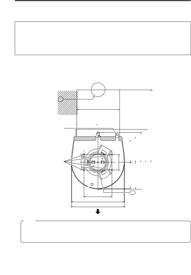
1 Check the mounting space.
●● Refer to the illustration, and determine where the unit is to be installed and in which direction it should be mounted. Factor in the unit mounting area and include space for the wires extending from its rear panel.
●● The asterisk () in the illustration marks the position and dimensions of the hole for mounting the mount bracket.
Through-hole for cable ø 40 (ø 1-9/16) [reference]
130 (5-1/8)
(Space for the wires from the rear panel)
Hole for mounting the main |
|
66 (2-19/32) |
|
|
|
||
|
|
|
|
unit mounting screw |
|
|
|
|
|
|
Hook for mounting the
drop-prevention wire 

 Unit mounting area


Mount bracket 
() Holes for mounting the |
(1-13/16) |
mount bracket: ø 4.5 × 4 |
() 46 |
|
Hole for checking 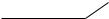
the positioning
() 83.5 (3-9/32)
156 (6-1/8)
160 (6-5/16)
Unit: mm (inch)
|
|
|
|
|
|
|
|
|
-7/16) or more |
for the wires) |
|
|
|
|
|
|
|
|
|
|
|||
|
|
|
|
|
90 (3-17/32) |
|
99 (3-29/32) |
290 (11 |
(Space |
||
|
|
|
|
|
|
|
|||||
|
|
|
|
|
|
||||||
65 (2-9/16) |
|
77 (3-1/32) |
|
|
|
||||||
|
|
|
|
|
|
|
|
|
|
|
|
78 (3-1/16) |
|
80 (3-5/32) |
|
|
|
|
|
|
|
||
|
|
|
|
|
|
|
|
|
|
|
|
Hole for installing the WV Q105A direct ceiling mount bracket
[ø 60 (ø 2-3/8)]
The front panel of the unit on this side
Notes
●● Make connections for each cable within the ceiling beforehand, and pass the cables through a cable-routing hole in preparation for making connections for and installing the unit.
●● For a power outlet which is used on the ceiling, be absolutely sure to take measures to deal with the tracking that may be caused by the accumulation of dust and other foreign matter.
8

How to install and connect the unit (continued)
2 Mount the mount bracket onto the installation surface.
●● Use the bracket mounting screws [M4, bind-head: 10 mm (13/32 inches) long] supplied with the unit. ●● For proper clamping torque, securely attach the screws using the specified tools.
Screw diameter |
Clamping torque |
M4 |
1.47 N · m {15 kgf · cm} |
Instructions
Installation
Bracket mounting screws × 4 (supplied) (M4, bind-head)
Note
●● Use only the screws supplied with the unit. Do not use any other screws such as wood screws, nails, etc.
3 Attach the drop-prevention wire.
●● Pull out the drop-prevention wire from the bottom panel of the unit, and engage the end with the wire ring through the hole of the mount bracket hook.
●● Pull the drop-prevention wire, and check that it has been attached securely to the hook.
Holding spring
End of hook
Pull out the drop-prevention wire, and engage it with the mount bracket hook.
Drop-prevention wire
Notes
●● Do not do this work while holding the camera head since doing so may result in malfunctioning of the unit.
●● The drop-prevention wire is designed to be used for installation where the unit is suspended from an overhead surface so do not subject it to the weight of units other than the unit.
9
How to install and connect the unit (continued)
4 Mount the unit.
●● Align the position of the hole for checking the positioning with the status display lamp.
●● Align the holes on the camera main unit used to insert the bottom panel with the protrusions on the mount bracket used for inserting the camera, push the camera to the bracket firmly, and rotate the main unit by about 15 degrees in the direction of the arrow.
●● Secure the unit to the mount bracket using the main unit mounting screw (M3) as supplied. ●● Attach the mount bracket securely with the prescribed tool using the clamping torque below.
Be absolutely sure to verify that none of the screws are loose.
Screw diameter |
Clamping torque |
M3 |
0.78 N · m {8 kgf · cm} |
Hole for checking the positioning
On the mount bracket: Protrusions
(×3) used for inserting the camera
Approx.
15°
On the camera main unit: Holes (×3) used to insert the bottom panel
Status display lamp
Main unit mounting screw (M3 screw) (with flat washer, spring washer)
Notes
●● Do not do this work while holding the camera head since doing so may result in malfunctioning of the unit. ●● Use only the screws supplied. Do not use any other screws.
●● Check that the unit has been mounted securely with no tilting or wobbling.
●● The unit must be secured without fail using the main unit mounting screw before any of the cables are connected.
5 Check the mounting.
Check out the following points.
•The main unit mounting screw must be mounted securely.
•The unit must not tilt, and it must be mounted exactly.
•The unit must be securely installed.
•The unit pedestal part must not rotate even when an attempt is made to turn it.
10
How to install and connect the unit (continued)
6 Connect the rear panel connectors.
Anchor the AC adaptor cable in place using the cable clamp.
LAN cable (for RS-422)
|
●● |
|
|
How to secure the AC |
|
|
adaptor cable |
|
|
A Loosely secure the cable |
|
|
clamp. |
|
AC adaptor cable |
Cable clamp |
|
LAN cable |
|
|
RS-232C cable |
|
|
HDMI cable |
|
|
SDI cable |
Loosely secure the cable clamp in |
|
Coaxial cable (for G/L IN) |
||
the area shown above. |
B Fasten the cable clamp.
Strap part
Take hold of the strap part, slide the cable clamp until it stops moving, and then secure it tightly.
Note
●● Always disconnect the power supply before connecting or disconnecting cables. Connecting or disconnecting cables while the power is turned on may result in malfunctions.
The unit is in the standby condition when the AC adaptor is connected.
The primary circuit is always “live” as long as the AC adaptor is connected to an electrical outlet.
Instructions
Installation
11
How to install and connect the unit (continued)
■■When using the WV Q105A (optional accessory)
It is recommended that you provide an inspection opening or other such space for access purposes in the area near where the equipment is installed in order to facilitate installation and the wiring connections work.
Before mounting the mount bracket, check that the installation location is strong enough to withstand the total mass (approx. 2.0 kg [4.41 lb]) which will be exerted once the camera is mounted.
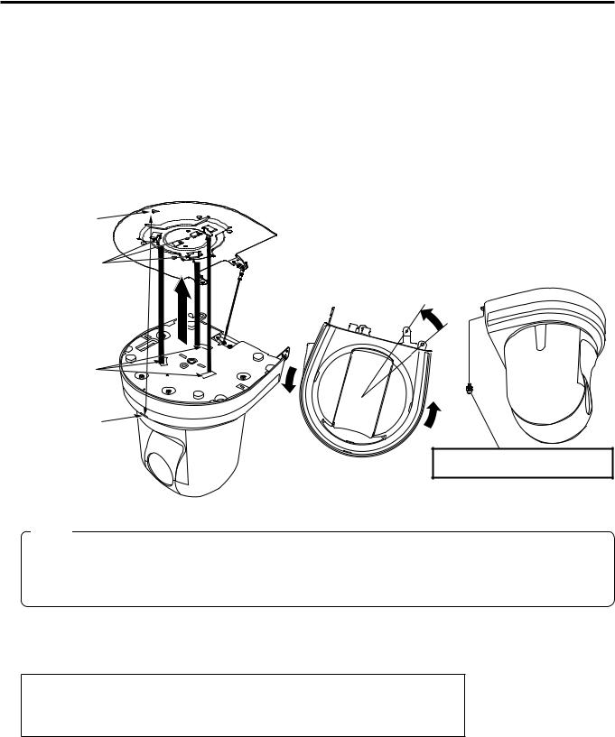
When installing the unit on a ceiling, ensure that there is at least 100 mm (3-15/16 inches) of space above the ceiling panel in the place where the unit will be used.
The unit can be installed on a ceiling panel with a thickness ranging from 5 mm (3/16 inches) to 40 mm (1-9/16 inches). The drop-prevention wire (supplied with the WV Q105A) must be used when mounting the direct ceiling mount bracket.
Concrete ceiling
Height above ceiling panel: At least 100 mm (3-15/16 inches)
Ceiling panel (plasterboard, etc.) with  a thickness from 5 mm (3/16 inches)
to 40 mm (1-9/16 inches)
Anchor bolts
●● Withdrawal strength: 196 N {20 kgf} or more
The anchor bolts must not protrude beneath the ceiling panel.
ø 60 mm (2-3/8 inches)
When installing the unit on a ceiling
1 Refer to the Operating Instructions of the WV Q105A direct ceiling mount bracket, and attach the
WV Q105A as well as the drop-prevention wire angle and drop-prevention wire supplied with the WV Q105A to the anchor bolts.
Mounting the anchor bolts and direct ceiling mount bracket ()
This job is facilitated if the direct ceiling mount bracket is loosely secured to the ceiling panel in one place, and the direct ceiling mount bracket and anchor bolts are vertically aligned before the nuts are tightened up.
2 First, remove the screws which were loosely fastened in step 1, and then align the camera mount bracket of the AW UN70 with the screw holes in the WV Q105A direct ceiling mount bracket and mount it in place.
●● Use the mounting screws (the M4-L60 Phillips head screws with adhesive) supplied with the WV Q105A as the mounting screws.
●● Fasten the AC adaptor securely to the bottom or other surface of the reinforcing member made of channel steel where dust and other foreign matter will not accumulate.
●● Do not place the AC adaptor directly onto the ceiling panel or other such surface.
|
Space above the ceiling |
|
|
Drop-prevention wire |
|
(): Fasten here using the nut. |
|
angle (Supplied with |
|
|
Direct ceiling mount bracket WV Q105A (optional accessory) |
WV Q105A) |
Anchor bolts |
|
|
|
|
|
|
Drop-prevention wire |
|
|
Plasterboard or other ceiling panel |
|
|
|
|
(Supplied with WV Q105A) |
|
|
Channel steel |
|
|
|
|
Inspection opening recommended |
|
|
Camera mount |
• The installation and wiring connection |
|
||
work is facilitated if an inspection |
|
|
bracket (Supplied |
opening is provided for access purposes. |
|
with AW UN70) |
|
Mounting screws × 4 |
|
(Ceiling |
|
(Supplied with WV Q105A) |
|
||
|
panel) |
||
|
|
|
|
|
|
AW UN70 |
Secure the AC adaptor firmly to a |
|
|
|
member made of channel steel. |
3 Install the AW UN70 camera by following the procedure starting with step 3 on page 9.
12
How to install and connect the unit (continued)
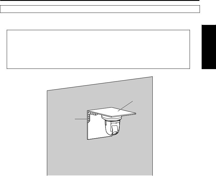
When installing the unit on a wall (installation example)
1 Before proceeding, fashion an L shaped mounting fixture, and attach the fixture securely to the wall where the unit will be installed.
IMPORTANT
●● Before installing the unit, check that the surface of the wall where the unit will be installed is strong enough to bear not only the total weight (approx. 2.0 kg [4.41 lb]) of the camera once it has been installed but also the weight of the L-shaped mounting fixture and its supports.
●● Use supports that are strong enough to withstand the total weight of the camera once it has been installed and any vibration or other forces to secure the L-shaped mounting fixture.
If the supports are not capable of bearing this weight and forces, the unit may become detached from the installation surface or it may fall off, possibly causing injury.
Instructions
Installation
L-shaped mounting fixture
Support
AW UN70
2 Refer to steps 1 to 3 in “When installing the unit on a ceiling” (page 12), and install the AW UN70.
13
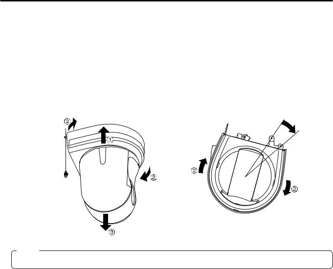
Removing the camera
1
2
3
4
Turn off the circuit breaker and power.
Disconnect the cables.
Disconnect the power cable, video cable, and control cable, etc.
Remove the main unit mounting screw used to secure the unit and mount bracket.
Push the unit (A). Turn it approximately 15 degrees away from the installed position (B), and remove it (C).
Approx.
15°
Main unit mounting  screw (M3 screw)
(with flat washer, spring washer)
Note
●● Do not do this work while holding the camera head since doing so may result in malfunctioning of the unit.
5 Disengage the drop-prevention wire from the mount bracket.
14
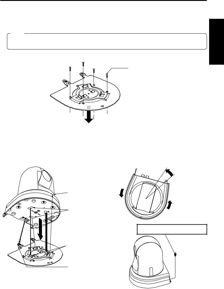
Stand-alone installation
(when the mount bracket is going to be used)
The same steps are followed as for the kind of installation where the unit is suspended from an overhead surface (pages 8 to 11).
1 Check the mounting space.
Note
●● As with installing the unit suspended from an overhead surface, carefully check the space where the unit will be mounted, and then decide if it is appropriate to install the unit in that space.
2 Mount the mount bracket onto the installation surface.
Bracket mounting screws × 4 (supplied) (M4, bind-head)
Instructions
Installation
3
4
Attach the drop-prevention wire.
Mount the unit.
●● Align the position of the hole for checking the positioning with the status display lamp.
●● Align the holes on the camera main unit used to insert the bottom panel with the protrusions on the mount bracket used for inserting the camera, push the camera to the bracket firmly, and rotate the main unit by about 15 degrees in the direction of the arrow.
●● Secure the unit to the mount bracket using the main unit mounting screw (M3) as supplied.
Approx.
15°
Status display lamp
On the camera main unit:
 Holes (×3) used to insert
  the bottom panel
Main unit mounting screw (M3 screw) (with flat washer, spring washer)
On the mount bracket:
Protrusions (×3) used for

 inserting the camera
Hole for checking the

 positioning
Attach the drop-prevention wire.
15
Stand-alone installation (when the mount bracket is going to be used) (continued)
5 Check the mounting.
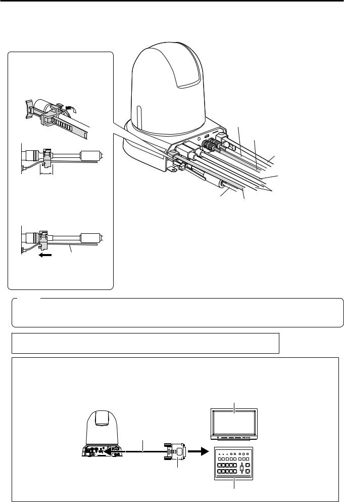
6 Connect the rear panel connectors.
●●How to secure the AC adaptor cable
A Loosely secure the cable clamp.
Cable clamp
Loosely secure the cable clamp in the area shown above.
B Fasten the cable clamp.
Strap part
Coaxial cable (for G/L IN)
|
SDI cable |
|
|
LAN cable |
|
|
(for RS-422) |
|
|
HDMI cable |
|
|
RS-232C cable |
|
AC adaptor |
LAN cable |
|
cable |
||
|
Take hold of the strap part, slide the cable clamp until it stops moving, and then secure it tightly.
Note
●● Always disconnect the power supply before connecting or disconnecting cables. Connecting or disconnecting cables while the power is turned on may result in malfunctions.
The unit is in the standby condition when the AC adaptor is connected.
The primary circuit is always “live” as long as the AC adaptor is connected to an electrical outlet.
Note for connecting with an HDMI cable
When connecting with an HDMI cable using an HDMI-to-DVI converter, etc., be sure to connect the HDMI cable to the connector of the AW UN70 last.
Connecting the HDMI cable to the connector of the AW UN70 first may result in malfunction.
Monitor
HDMI cable |
|
AW UN70 2 |
1 |
HDMI-to-DVI converter, etc.
Switcher
16
Stand-alone installation
(when the mount bracket is not going to be used)
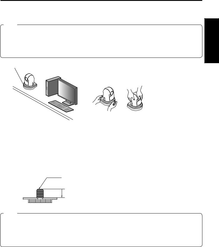
■■When installing the unit on a desktop
Place the unit flat on the surface.
Notes
●● Install the unit in a stable location which will not be susceptible to shaking. If the unit is installed in a location which is susceptible to shaking, this will cause the unit’s images to shake in turn.
●● Take care not to allow the unit to fall or otherwise be damaged during installation. ●● When carrying the unit, do not hold it by its head.
●● Do not take hold of the camera head or rotate it. Doing so may cause malfunctioning.
●● Take care not to pull the connected cables. Doing so may cause the unit to fall and/or it may result in injury.
Ensure that the unit will not fall off.
Correct Incorrect
Instructions
Installation
■■When mounting the unit on a tripod
Attach the tripod to the threaded holes for mounting the camera on the camera’s bottom panel. Place the tripod on a completely flat and level surface.
Tighten the screws by hand to mount the tripod securely.
Use screw for mounting the tripod that satisfy the following standard.
Screw for mounting tripod 1/4-20UNC, ISO1222 (6.35 mm)
 4.5 mm to 6 mm (0.18 to 0.24 inches)
Notes
●● Do not install the unit where people will be passing back and forth.
●● When using the unit mounted on a tripod, do not put the tripod high above the floor level.
●● Mount the unit securely so there is no looseness. Looseness may cause the unit to fall off and/or result in injuries.
●● When the unit is going to be used for a prolonged period of time, take steps to ensure that the unit will not topple or fall over and that it will not fall off or fall down. After using the unit, restore the installation location to its original state without delay.
17
Loading...