


Indoor Pan/Tilt Head
AW-PH300


Before attempting to connect or operate this product, please read these instructions completely.

CAUTION
RISK OF ELECTRIC SHOCK
DO NOT OPEN
CAUTION:
TO REDUCE THE RISK OF ELECTRIC SHOCK, DO NOT REMOVE COVER (OR BACK). NO USER SERVICEABLE PARTS INSIDE.
REFER SERVICING TO QUALIFIED SERVICE PERSONNEL.
|
The lightning flash with arrowhead sym- |
|
|
bol, within an equilateral triangle, is |
|
|
intended to alert the user to the pres- |
|
|
ence of uninsulated "dangerous voltage" |
|
|
within the product's enclosure that may |
|
SA 1965 |
be of sufficient magnitude to constitute a |
|
risk of electric shock to persons. |
||
|
The exclamation point within an equilateral triangle is intended to alert the user to the presence of important operating and maintenance (servicing) instructions in the literature accompanying the appliance.
SA 1966
For U.S.A
Warning:
Do not install this product near any object that burns easily. In case of using a halogen lamp, installation of it near such an object could cause a fire due to the heat generated by the lamp.
For CANADA
This digital apparatus does not exceed the Class A limits for radio noise emissions from digital apparatus set out in the Radio Interference Regulations of the Canadian Department of Communications.
The serial number of this product may be found on the bottom of the unit.
You should note the serial number of this unit in the space provided and retain this book as a permanent record of your purchase to aid identification in the event of theft.
Model No.
Serial No.
WARNING:
TO PREVENT FIRE OR ELECTRIC SHOCK HAZARD, DO NOT EXPOSE THIS APPLIANCE TO RAIN OR MOISTURE.
CONTENTS |
|
FEATURES .......................................................................................................................................................................................... |
2 |
PRECAUTIONS ................................................................................................................................................................................... |
3 |
MAJOR OPERATING CONTROLS AND THEIR FUNCTIONS ............................................................................................................ |
4 |
INSTALLATION ................................................................................................................................................................................... |
6 |
SPECIFICATIONS ............................................................................................................................................................................... |
21 |
ACCESSORIES ................................................................................................................................................................................... |
22 |
-1-

FEATURES
•The AW-PH300 is a compact pan/tilt head capable of tilting up to 95° up or 95° down and panning up to 300°. It is mounted upright or suspended.
•The pan/tilt head carries a camera and lenses for a total weight of 4 kg.
•The pan/tilt head can be directly controlled using the Pan/tilt Control Panel AW-RP301 or AW-RP305. (The Control Panel cannot control the camera.)
•A camera and pan/tilt head can be directly controlled using the Hybrid Control Panel AW-RP501.
•Up to five cameras with pan/tilt heads can be directly controlled using the Multi-Hybrid Control Panel AWRP505 in combination with the Multiport Hub AWHB505.
•The pan/tilt head can be controlled from a personal computer via an RS-232C. However, simultaneous control with a personal computer and a control panel is not possible.
•The pan/tilt head can also be controlled using a contact type controller.
-2-
PRECAUTIONS
•Avoid using the pan/tilt head in the kitchen or other places full of steam and oil fume.
•The pan/tilt head has a maximum load capacity of 4kg. Do not use it for a load over 4 kg.
•Do not install the pan/tilt head outdoors, or at a place over 45°C, or at a cold place below −10°C.
Ambient humidity must be less than 90%.
•Mounting screws must be locally purchased because they are not supplied.
Choose screws appropriate to the material of the mounting place and the load on the pan/tilt head.
•Use only with AC Adaptor, Model AW-PS300.
•In handling the pan/tilt head, be sure to hold it by the base.
Do not lift the pan/tilt head by the rotary part of it. Otherwise, something may go wrong with the head.
•Do not turn the pan/tilt head by the rotary part of it. Otherwise, something may go wrong with the head.
•Dropping the pan/tilt head or subjecting it to a strong shock can cause a failure or an accident.
•Keep the pan/tilt head more than 1 meter away from the monitors.
•The pan/tilt head uses a manganese dioxide lithium battery (CR2032).
Be sure to remove the battery before disposing of the pan/tilt head or the printed wiring boards in the head.
Be sure to dispose of a removed battery, or an old battery removed to be replaced, according to the applicable provisions of law.
Do not dispose of it as ordinary trash.
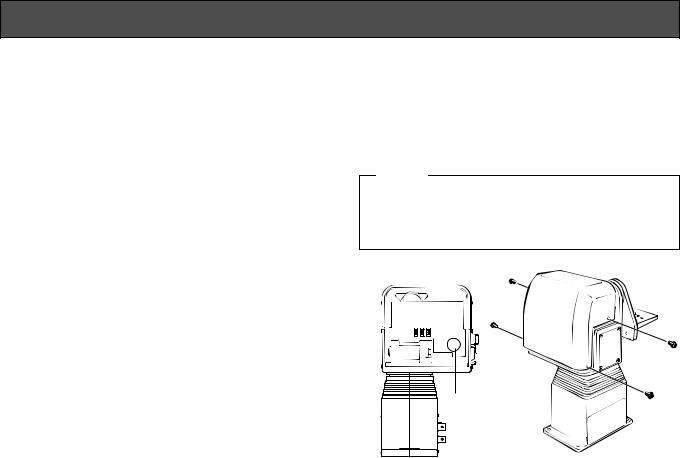
The battery is located as shown in the figure below. To remove the battery, refer to Battery Replacement under the Replacement of Expendables at page 20.
Caution
Danger of explosion if battery is incorrectly replaced. Replace only with same or equivalent type recommended by the manufacturer. Dispose of used battteries according to the manufacturer`s instructions.
SW1 SW2 SW3
Battery |
-3-

MAJOR OPERATING CONTROLS AND THEIR FUNCTIONS
y u
i
!4
q |
q |
|
|
|
w |
u |
|
w |
e |
||
|
|||
|
|
||
e |
r |
|
|
|
|
|
t |
t |
|
o |
|
!2 |
|
!1 |
!3 |
|
 !0
!0
-4-
qTilting Arm (supplied)
This arm tilts the head.
wTilting Arm Fixing Screws (supplied)
4 screws are supplied to fasten the tilting arm.
eCamera Mounting Plate (supplied)
Used to fasten the camera.
rCamera Guide Pin
This pin sets the mounting direction of the camera.
tCamera Mounting Screw
This screw fastens the camera. (U 1/4”-20 UNC)
yPanning Head
The head rotates in panning directions.
uTally Indicators (2 pcs.)
A selection signal lights them red.
iCamera Connector Panel
To connect a camera and lens.
o Base
!0Mounting Holes
There are 4 holes to mount the pan/tilt head.
!1Wire Rod Mounting Hole
To pass a wire to prevent the pan/tilt head from falling.
!2Control Connector Panel
To connect a Control Panel (AW-RP301, RP305, or RP501) or the Multiport Hub (AW-HB505) and Pan/tilt Head AC Adapter (AW-PS300)
!3Side Blank Panel
A spare to be used in changing the mounting position of Control Connector Panel !2
!4Bottom Blank Panel
A spare to be used in changing the mounting position of Control Connector Panel !2
-5-
INSTALLATION
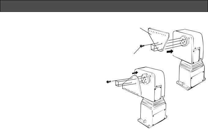
■ Assembling the Pan/tilt Head |
<Mounting suspended> |
In handling the pan/tilt head, be sure to hold it by the |
Tilting Arm |
|
|
base. |
|
● Installing the Tilting Arm |
|
Fasten the Tilting Arm q (supplied) with the Tilting Arm |
|
Fixing Screws w (supplied). The way of mounting the |
|
arm differs depending on the direction of pan/tilt head |
|
installation. (See the figure right.) |
Tilting Arm Fixing Screws |
Note: Do not use other than the supplied tilting arm fixing screws to fasten the tilting arm.
<Mounting upright>
-6-
 Loading...