


Arbitrator 360 Hardware Installation ver 2.4
(Distribution Center version)
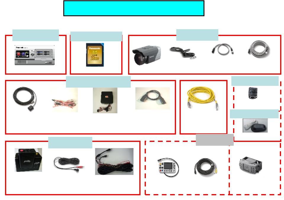
1. Arbitrator Units and Cables
AG-CPD20P RP-SDW32GP1K
Recorder (VPU) |
32GB SDHC Card |
PAPDC2462-2859
GPS Antenna |
Power Cable |
Power |
|
for Recorder |
Distribution Box |
||
|
CCR24PNA
Digital Wireless |
In Car Mic |
|
|
Mic Reciever & |
Receiver Cable |
||
|
|||
|
|
||
Transmitter |
|
|
AG-CK10P
|
Cable |
Camera Cable |
Camera Mount |
(Short) |
(Long) |
TT-ARBM56P06
3rd-6th Camera
A360-WLSAP-BWT
LAN Cable (Crossing type)
OPTIONS AP-WiFi-Modem
|
|
CN258IR-P |
AG-RCP30P |
|
|
|
|
|
|
|
|
2nd Backseat
Camera

2. Arbitrator in-car System Configuration
Camera 2 |
Control Panel |
Toughbook |
Front End |
|
(backseat) |
(Option) |
|||
(In car PC) |
Application |
|||
(Option) |
AG-RCP30P |
|||
|
|
|||
|
|
CN258IR-P
|
Video Out 1 |
Ethernet |
|
|
|
Cable for |
|
||
|
for LPR/ |
|
||
|
Wired |
|
||
|
Monitor etc |
|
||
Option Camera Examples |
Upload |
VPU |
||
|
Camera 3 (LPR) |
AG-CPD20P |
|
Camera 4 (Left) |
||
|
||
Camera 5 (Right) |
|
|
Camera 6 (Back) |
|
GPS
Antenna
Use the mirror mode for Camera 4, 5 and 6.
If no mirror mode for these, connect Camera 4 (Left) to Video 5 and Camera 5 (Right) to Video 4.
RX/TX
Camera 1 (Front)
AG-CK10P
Power
2nd/3rd
WMIC
RX/TX
(Option)
Serial (RS-232C)
In Car Mic for Radar Gun AP-WiFi- Modem
WMIC RX/TX |
|
|
|
|
|
|
From 3rd |
|
|
||
A360-WLSAP-BWT |
|||||
CCR24PNA |
|
Vendor |
|
||
|
|
|
|
||
|
|
|
|
|
Cable Kit
AG-CR13P
Car Battery
12V/24V
Box
16 Triggers (Siren/Light Bar/Brake/ WMIC etc)

Appendix: Camera 4, 5 and 6 video image and connection
1 (Camera 1) Front 3
LPR
If Left Camera (Cam4), Right Camera (Cam5) and Back Camera (Cam6) have the Mirror mode, Connect Cam 4 to the “video in 4”, Cam5 to “video in 5” and Cam6 to “video in 6”
Cam4 Cam5
Left Right
2 R-Seat
Cam6
Back
 Officer Walking Direction
|
1, 2 or 3 |
|
|
1, 2 or 3 |
6 |
|
|
|
|
|
|
||
|
|
|
|
|
|
|
|
|
|
|
|
4 |
5 |
|
4 |
6 |
5 |
|
||
|
|
|
|
|||
|
|
|
|
|
|
|
Cam4 |
|
Cam5 |
Cam4 |
Cam5 |
||
Image will be moved 4, 6, 5 in order from left to right.
If Left Camera (Cam4), Right Camera (Cam5) and Back Camera (Cam6) do NOT have the Mirror mode, Connect Cam 4 to the “video in 5”, Cam5 to “video in 4” and Cam6 to “video in 6”
1, 2 or 3 |
1, 2 or 3 |
6 |
4 |
6 |
5 |
4 |
5 |
Cam5 |
|
Cam4 |
Cam5 |
Cam4 |
|
||||
|
|
|
Image will be moved 5, 6, 4 in order from right to left.

3.Install VPU using Mounting Bracket
1.To center console
2. To trunk

4. Power cable harness for VPU, Wireless MIC and 2nd camera (Distribution Center)
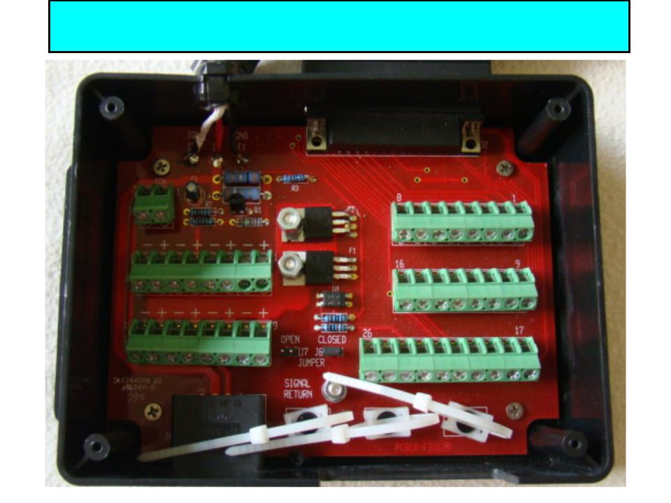
4. Power cable harness for VPU, Wireless MIC and 2nd camera (Distribution Center inside picture)
 Loading...