


AW-HE2P
Getting startedInstallation
Instructions
Operating
Instructions
Operating Instructions <Basics>
HD Integrated Camera
Model No. AW-HE2P
AW-HE2E
Please read these instructions carefully before using this product, and save this manual for
future use.
Installation Instructions provided
≥ Die Bedienungsanleitung in Deutsch ist als
PDF-Datei in der CD-ROM enthalten. (l 2)
≥ Le mode d’emploi en français est fourni sous
forme de fichier PDF sur le CD-ROM. (l 2)
≥ Le istruzioni per l’uso in italiano sono
contenute in un file PDF sul CD-ROM. (l 2)
≥ Las instrucciones de funcionamiento en
español se encuentran en un archivo PDF
del CD-ROM. (l 2)
≥ Документ Инструкция по эксплуатации на
русском языке находится в виде PDF-
файла на диске CD-ROM. (l 2)
How the Operating Instructions are configured
This <Basics> describes the procedure for basic operation and installation. Before
installing this unit, be sure to take the time to read through <Basics> to ensure that the unit
will be installed correctly.
For more detailed operating instructions, please refer to <Operations and Settings> (PDF
file) recorded on the attached CD-ROM.
≥ To open <Operations and Settings>, please refer to page 2.
≥ This <Basics> is also contained as a PDF file on the CD-ROM supplied with the unit.
F1012KY0 (2200 A)
Printed in Japan VQT4N15
ENGLISH

2
VQT4N15
ENGLISH
≥ How to open the operating instruction
manual PDF files
Discontinue installation if the installation
screen of the software opens as a result of
inserting the CD-ROM.
When [INDEX.pdf] on the CD-ROM is
opened, a list of the operating instruction
manuals will be displayed.
Click on the document name of the
manual to be opened.
≥ Adobe Reader is required to read PDF
files.
It can be downloaded from the home
page of Adobe Systems.
DEUTSCH
≥ Öffnen der PDF-Dateien der
Bedienungsanleitung
Brechen Sie die Installation ab, falls beim
Einlegen der CD-ROM der
Installationsbildschirm der Software
erscheint.
Wenn [INDEX.pdf] auf der CD-ROM
geöffnet wird, erscheint eine Liste der
Bedienungsanleitungen.
Klicken Sie auf den Dokumentennamen
der zu öffnenden Anleitung.
≥ Zum Lesen der PDF-Dateien benötigen
Sie Adobe Reader.
Dieses Programm kann von der
Homepage von Adobe Systems
heruntergeladen werden.
FRANÇAIS
≥ Comment ouvrir les fichiers PDF des
manuels du mode d’emploi
Arrêter l’installation si l’écran d’installation
du logiciel s’ouvre quand le CD-ROM est
inséré.
Quand [INDEX.pdf] sur le CD-ROM
s’ouvre, la liste des manuels du mode
d’emploi s’affiche.
Cliquer sur le nom du document
correspondant au manuel à consulter.
≥ Adobe Reader est nécessaire pour lire
les fichiers PDF.
Ce logiciel peut être téléchargé depuis
la page d’accueil d’Adobe Systems.
ITALIANO
≥ Come aprire i file dei manuali di
istruzioni per l’uso
Se inserendo il CD-ROM si apre la
schermata di installazione del software,
interrompere l’installazione.
Aprendo [INDEX.pdf] sul CD-ROM, viene
visualizzato un elenco di manuali di
istruzioni per l’uso.
Fare clic sul nome del documento
corrispondente al manuale da aprire.
≥ Per leggere i file PDF è necessario
Adobe Reader.
Il programma può essere scaricato dal
sito Web di Adobe Systems.
ESPAÑOL
≥ Modo de abrir los archivos PDF que
contienen el manual de las
instrucciones de funcionamiento
Interrumpa la instalación si la pantalla de
instalación del software se abre como
resultado de insertar el CD-ROM.
Cuando se abra [
INDEX.pdf
] en el
CD-ROM
se visualizará una lista de los manuales de
instrucciones de funcionamiento.
Haga clic en el nombre de documento del
manual que va a abrir.
≥ Para leer los archivos PDF se necesita
el programa Adobe Reader.
Este programa se puede descargar de
la página inicial de Adobe Systems.
РУССКИЙ
≥ Как открыть PDF-файлы инструкции
по эксплуатации
Прекратите установку, если в результате
загрузки диска CD-ROM появилось окно
установки программного обеспечения.
При открытии файла [INDEX.pdf] на
диске CD-ROM будет отображен список
инструкций по эксплуатации.
Щелкните название документа
руководства, чтобы открыть его.
≥ Для чтения PDF-файлов потребуется
Adobe Reader.
Данное программное обеспечение
можно скачать с домашней страницы
Adobe Systems.

3
VQT4N15
Getting startedInstallation
Instructions
Operating
Instructions
Contents
Getting started
Read this first!........................................... 4
Accessories...............................................6
Optional accessories ........................... 7
Names and Functions of Main Parts .......8
Unit Configuration ............................... 8
Names and Functions of
Main Parts ........................................... 8
Mounting the Stand and
the Stand Cover ................................10
Tilting the Camera Up and Down ......10
Detaching and Attaching
the Rear Cover .................................. 11
Detaching and Attaching
the Middle Ring Portion ..................... 12
Installation Instructions
Information for Your Safety.................... 14
Installation precautions.......................... 15
How to connect and
install the unit.......................................... 18
Checking the installation location ...... 18
Preparing the power source .............. 19
Connecting the cables ......................19
Ceiling-suspended Installation ..........21
Standing Installation .......................... 22
Mount to a Tripod .............................. 23
Connection with Other Devices ............. 24
Connections with an HD monitor .......24
Connections with a controller
(AW-RP50, optional) ......................... 24
System example 1 (IP control) ..........25
System example 2 (IP control) ..........26
Operating Instructions
Information for Your Safety.................... 27
Characteristics........................................ 33
Cautions for use...................................... 35
Required personal computer
environment ............................................ 37
Network settings..................................... 38
Starting the Web Setting Screen ........... 40
Starting the Web Setting Screen
(Live Screen/Setup Screen) .............. 40
Wireless remote controller .................... 44
Names and Functions of
Main Parts ......................................... 44
Usable Range for the Wireless
Remote Controller ............................. 45
Setting the Remote Control ID of
the Camera ....................................... 45
Before Operating With the Wireless
Remote Controller ............................. 46
About copyright...................................... 47
Specifications ......................................... 49

4
VQT4N15
∫ References made in this manual
References made are as per below:
≥ Pages for reference are indicated by an arrow, for example: l 00
≥ AW-HS50 N, AW-HS50E # [AW-HS50]
≥ AW-RP50 N, AW-RP50E # [AW-RP50]
≥ Remote Camera Controller # [Controller]
∫ Regarding photos and illustrations in this manual
Please note that the product profile sketches, illustrations, menu screens, etc. in this manual
differ slightly from the actual product.
∫ Regarding personal computer screenshots
Descriptions are provided using screenshots from Windows 7.
∫ To prevent unauthorized use
≥ Your user name and password on the web setting screen.
jDo not use the default user name and password. Make sure you change them.
jDo not set the same character string for the user name and password.
jDo not allow anyone else to see the user name and password, and do not tell them to
anyone else.
jIn the case that a third party sets up/performs settings for the unit, be sure to change the
user name and password after the third party has done so.
jWhen requesting repairs, restore the default settings with the INIT button (l 9), and then
reset your user name and password.
(When the default settings are restored, the default network settings are also restored.
Please make a note of the network settings, user name, and password.)
≥ Set a screensaver protected with a password for the personal computer.
∫ Precautions when requesting repairs
Take note of each setting you have changed in the camera when requesting repairs. Your
current settings may be deleted or modified.
∫ When disposing of/transferring the unit
The unit records personal information related to your operations. When you part with the unit
due to such reasons as disposal or transfer, make sure to restore the default settings with the
INIT button (l 9) and erase recorded information.
∫ Privacy and Image Rights
Set up and use the camera at your own responsibility. Take into consideration subjects’
privacy (including sounds picked up by the microphone), portrait rights, and the like first.
Getting started
Read this first!

5
VQT4N15
∫ Disclaimer of warranty
IN NO EVENT SHALL Panasonic Corporation BE LIABLE TO ANY PARTY OR ANY
PERSON, EXCEPT FOR REPLACEMENT OR REASONABLE MAINTENANCE OF THE
PRODUCT, FOR THE CASES, INCLUDING BUT NOT LIMITED TO BELOW:
1) ANY DAMAGE AND LOSS, INCLUDING WITHOUT LIMITATION, DIRECT OR
INDIRECT, SPECIAL, CONSEQUENTIAL OR EXEMPLARY, ARISING OUT OF OR
RELATING TO THE PRODUCT;
2) PERSONAL INJURY OR ANY DAMAGE CAUSED BY INAPPROPRIATE USE OR
NEGLIGENT OPERATION OF THE USER;
3) UNAUTHORIZED DISASSEMBLE, REPAIR OR MODIFICATION OF THE PRODUCT
BY THE USER;
4) INCONVENIENCE OR ANY LOSS ARISING WHEN IMAGES ARE NOT DISPLAYED,
DUE TO ANY REASON OR CAUSE INCLUDING ANY FAILURE OR PROBLEM OF
THE PRODUCT;
5) ANY PROBLEM, CONSEQUENTIAL INCONVENIENCE, OR LOSS OR DAMAGE,
ARISING OUT OF THE SYSTEM COMBINED BY THE DEVICES OF THIRD PARTY;
6) LOSS OF REGISTERED DATA CAUSED BY ANY FAILURE.
∫ Network security
As you will use this unit connected to a network, your attention is called to the following
security risks.
1) Leakage or theft of information through this unit
2) Use of this unit for illegal operations by persons with malicious intent
3) Interference with or stoppage of this unit by persons with malicious intent
It is your responsibility to take precautions such as those described below to protect yourself
against the above network security risks.
≥ Use this unit in a network secured by a firewall, etc.
≥ If this unit is connected to a network that includes personal computers, make sure that the
system is not infected by computer viruses or other malicious entities (using a regularly
updated antivirus program, anti-spyware program, etc.).
≥ Protect your network against unauthorized access by restricting users to those who log in
with an authorized user name and password.
≥ Take measures by authenticating the users of the unit in order to restrict access, for
example, so that the setting information contained inside the unit is not leaked over the
network.
≥ Do not install the camera in locations where the camera or the cables can be destroyed or
damaged by persons with malicious intent.
≥ Refrain from connections that use public lines.
Usage restrictions
Use of the same segment is recommended for the network in which the unit and the
controller or personal computer are connected.
If the equipment uses connections with different segments, events based on the settings
inherent to the network equipment, for instance, may occur so check this thoroughly prior to
operation.
6
VQT4N15
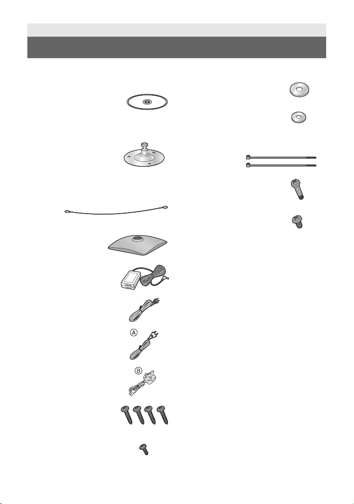
Check the accessories before using this unit.
≥ Refer to page 10 concerning the mounting
method for the stand and stand cover.
≥ Keep the screws, washers, bundling
bands, drop-prevention wire and stand
protrusion out of reach of children to
prevent swallowing.
Getting started
Accessories
CD-ROM
≥ Operating Instructions
(<Basics>, <Operations
and Settings>)
≥ Easy IP Setup Software
(EasyIpSetup.exe)
Stand
Remove the stand
protrusion, stand fixing
screw
and spring washer
when using a tripod. (l 23)
Drop-prevention wire
Stand cover
AC adaptor
AC cable
for AW-HE2P
AC cable
for AW-HE2E
for AW-HE2E
≥ In Saudi Arabia, always
use
B.
M4 screw
20 mm (0.787 q) length
(4 screws)
M3 screw
8 mm (0.315 q) length
Flat washer (for M4
screw)
Flat washer (for M3
screw)
Bundling band
(2 bands)
Perpendicular fixing
screw
(installed on the unit)
Horizontal fixing screw
(installed on the unit)

7
VQT4N15
Optional accessories
The following optional product is compatible with the unit:
Some optional accessories may not be available in some countries.
Product name (product number)
≥ Wireless remote controller (AW-RM50G)
≥ Remote Camera Controller (AW-RP50N, AW-RP50E)
≥ USB cable (K2KYYYY00221)
(contact a sales store for information about purchases)
Product numbers correct as of Oct. 2012. These may be subject to change.
8
VQT4N15
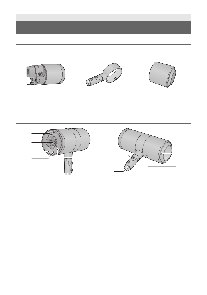
Unit Configuration
This unit consists of the camera body, middle ring portion and rear cover.
≥ Detaching and attaching the Rear Cover (l 11 )
≥ Detaching and attaching the Middle Ring Portion (l 12)
≥ The middle ring portion has a front and rear orientation. Take note of the front and rear
orientation when attaching the middle ring portion or passing cables through.
(l 12, 20)
Names and Functions of Main Parts
1 Internal stereo microphones
2Lens
3 Status display lamp
jOrange light: Standby mode
jGreen light: The unit is turned on
jFlashing green light:
The unit is receiving a wireless remote
control signal with a matching remote
control ID
jFlashing orange light:
The unit is receiving a wireless remote
control signal with a different remote
control ID
4 Tally lamp
5 Wireless remote control signal
light-sensing area (l 45)
6 Perpendicular fixing screw (l 10)
7 Horizontal fixing screw (l 10, 23)
8 Stand mounting hole (l 10, 23)
9 Bundling band eyelet (l 20)
10 Anti-theft wire mounting hole (l 20)
The anti-theft wire (available from a
hardware store) is attached here.
Getting started
Names and Functions of Main Parts
Camera body Middle ring portion Rear cover
2
3
4
5
1
6
7
8
9
10

9
VQT4N15
∫ When the rear cover is detached
11 RELEASE lever (l 12)
12 USB terminal [ ](l 20)
Power can be supplied from any device that
complies with USB battery charging
standards, including Micro USB AC/DC
converters for ordinary cell phones, personal
computers, or televisions. When doing so,
use the USB cable.
≥ Always use a genuine Panasonic USB
cable (K2KYYYY00221: optional).
13 HDMI terminal (l 20)
14 Drop-prevention wire mounting
portion (l 20)
15 LAN connector (l 20)
Use a category 5 or above LAN cable with a
maximum length of 100 m (328 ft.).
16 LAN lamp [LINK/ACT]
Lights up when data is transmitted/received
via LAN.
17 microSD card slot
This portion is used when updating the
firmware of the unit. (Not ordinarily used)
≥ Keep the microSD card out of reach of
children to prevent swallowing.
18 INIT button
If you press the button while the unit is
turned on, the user management settings
and the network settings are initialized.
Initialize using the following procedure.
1) Close the camera menu and the web
settings screen.
2) Press the INIT button.
3) Switch on the power again using the
power button.
19 Power button [ ]
If you press the button when the unit is in
standby mode or turned off, the unit is turned
on. If you press and hold the button when
the unit is in standby mode or turned on, the
unit is turned off.
∫ When the middle ring portion is detached
20 DC input terminal [DC IN] (l 20)
≥ Do not use any other AC adaptors except
the supplied one.
11
12
13
14
15
16
17
18
19
20
10
VQT4N15
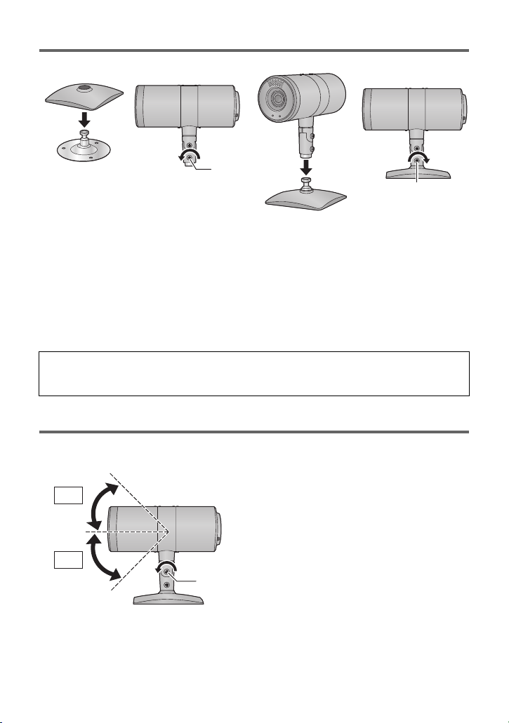
Mounting the Stand and the Stand Cover
1 (only when using the stand cover)
Put the stand cover on the stand.
2 Loosen the horizontal fixing screw A.
3 Insert the stand in the stand mounting hole.
4 Tighten the horizontal fixing screw A.
≥ Tightening torque: 1.176 N·m (12 kgf·cm)
≥ Tighten it firmly so that there is no wobbling.
Tilting the Camera Up and Down
When the perpendicular fixing screw A is loosened, the camera can be tilted approximately
45°up or down.
≥ After adjusting the position of the camera, firmly tighten the screw to fix the camera in
position.
(Tightening torque: 1.176 N·m (12 k
gf·cm))
When the horizontal fixing screw is loosened, the camera can be rotated 360° in the
horizontal direction.
Adjust the position of the camera to suit the installation location.
45°
45°
11
VQT4N15
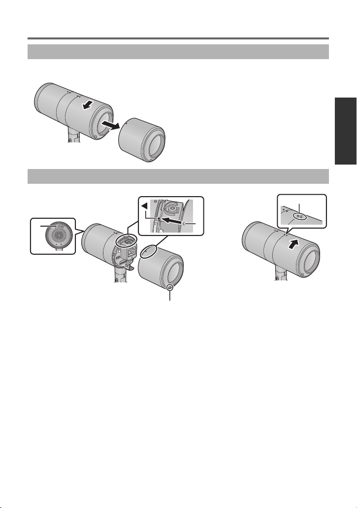
Detaching and Attaching the Rear Cover
Turn the rear cover in the direction of the arrow and detach it.
1 Align the mark 2 on the camera body with the mark A on the rear
cover and insert it.
≥ Attach the rear cover with the internal stereo microphones B facing up, and the bundling
band eyelet c facing down (the cover cannot be attached in the reverse order).
2 Attach the rear cover by turning it in the direction of the arrow.
≥ Align the middle ring portion and the mark D on the rear cover.
Detaching the Rear Cover
Attaching the Rear Cover
12
VQT4N15
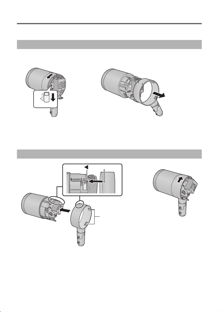
Detaching and Attaching the Middle Ring Portion
Detach the middle ring portion when connecting the AC adaptor or when installing the middle
ring portion upside down by suspending the camera from the ceiling.
≥ Detach the rear cover (l 11)
1 While sliding the RELEASE lever, turn the middle ring portion in the
direction of the arrow.
2 Pull the middle ring portion out from the camera body.
1 Insert the middle ring portion in the camera body.
≥ Insert the middle ring portion from the opposite side of the groove (A) into the camera
body.
≥ Align the mark B on the middle ring portion with the 2 mark on the camera body and
insert it.
Detaching the middle ring portion
Mounting the middle ring portion
RELEASE
13
VQT4N15
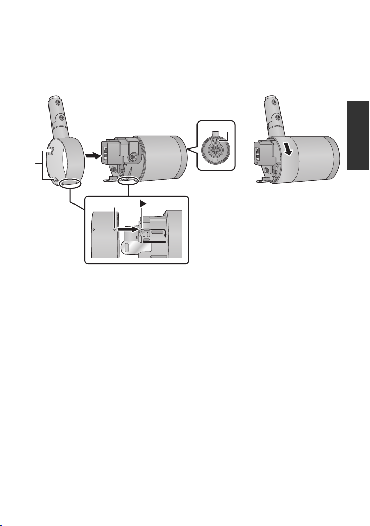
2 Turn the middle ring portion in the direction of the arrow to attach
the middle ring portion to the camera body.
≥ Turn it until there is a clicking noise and it locks into place.
∫ For ceiling-suspended installation
Mount the middle ring portion to the camera body while moving it up/down or rotating it.
1 Insert the middle ring portion in the camera body.
≥ Check which portions of the camera body are the top and bottom by looking at the
positions of the internal stereo microphones A.
≥ Insert the middle ring portion from the opposite side of the groove (B) into the camera
body.
≥ Align the mark C on the middle ring portion with the
1
mark on the camera body and
insert it.
2 Turn the middle ring portion in the direction of the arrow to attach
the middle ring portion to the camera body.
≥ Turn it until there is a clicking noise and it locks into place.

14
VQT4N15
Installation Instructions
Information for Your Safety
WARNING:
To prevent injury, this apparatus must be securely attached to the floor/wall/ceiling in
accordance with the installation instructions.
WARNING:
Installation should only be performed by qualified installation personnel.
Improper installation may result in the entire apparatus falling down and causing injury.

15
VQT4N15
To installation personnel
Read the “Installation Instructions” thoroughly and then perform the operation correctly and
safely.
Also, always read the “Information for Your Safety” (l 14) of this manual as they contain
important information.
After the installation, give the “Operating Instructions <Basics>” to the customer to save for
future use.
Ensure that the installation work complies with the technical standards governing
electrical equipment.
This unit is for indoor use only.
It cannot be used outdoors.
Avoid installation in a location where the unit will be exposed to direct sunlight for extended
periods or near a cooling or heating appliance.
Otherwise, deformation, discoloration, malfunctioning and/or problems in operation may
result. Operate the unit where it will not be splashed or sprayed by water.
Use the unit with an installation where the unit is suspended from an overhead surface
or with a stand-alone installation.
Do not use the unit on its side.
Concerning the installation location
Install the unit in a stable location which will not be susceptible to shaking. If the unit is
installed in a location which is susceptible to shaking, this will cause the unit’s images to
shake in turn.
Install the unit after conferring in detail with your dealer.
Install the unit on a ceiling that is strong enough (such as a concrete ceiling).
If the unit is to be installed on a ceiling which is not strong enough, reinforce the ceiling
sufficiently first.
Installation Instructions
Installation precautions
Panasonic does not accept any responsibility for accident or damage during installation if
procedure in this manual is not followed.
≥ When using screws to fix parts during installation, be sure to use the supplied screws.
Do not use wood screws, nails, etc.
In the case of a concrete ceiling, secure the unit using anchor bolts (for M4) or AY plug
bolts (for M4).
Tightening torque: 1.176 N·m (12 k
gf·cm )
≥ Installation conditions (ceiling-suspended installation/standing installation)
jCamera weight: 244
g (including stand, stand cover, middle ring portion and
rear cover)
jMinimum pulling strength (per screw): 147 N (15 k
gf)
jNo. of screws: 3 screws

16
VQT4N15
Do not install or use the unit in the following kinds of locations.
≥ On walls (where the unit would be installed sideways)
≥ In locations (including places such as under the eaves of a building) where the unit would
be directly exposed to rain or water
≥ In locations such as kitchens where there are high concentrations of steam and grease
≥ In outdoor locations or hot places where the temperature will exceed 40 oC (104 °F)
≥ In cold locations where the temperature will drop below 0 oC (32 °F)
≥ In locations where the humidity will exceed 80%RH
≥ In locations where chemicals are used such as near swimming pools
≥ At sea, in coastal areas or in locations where corrosive gases are emitted
≥ In locations where radiation, X-rays, or strong radio waves or magnetic fields are
generated
≥ In locations where the unit would be subject to a great deal of vibration such as on board a
vehicle or ship (this unit is not designed to be used in vehicles)
≥ In locations where the temperature is subject to sudden changes such as near the air
outlet of an air conditioner or near a door which allows the outside air to come in
What to avoid to ensure that the unit will perform stably over a prolonged period.
≥ Using the unit for a prolonged period in a location with high temperature and humidity
levels will cause its parts to deteriorate and shorten its service life.
≥ Ensure that a cooling unit or heating unit will not blow any air directly toward the installation
location.
Be absolutely sure to use the supplied stand and screws to install the camera.
≥ Do not mount the unit by employing any methods other than those specified.
≥ Do not remodel the stand or screws provided with the unit.
Before installation, always disconnect the power plug.
Tightening up the mounting screws
≥ Tighten up the screws and bolts securely to the degree that is appropriate for each of the
materials used in the mounting location and structures.
≥ After tightening up the screws and bolts, check that there is no unsteadiness and that the
parts have been tightened securely.
≥ Use the specified tools and tighten the screws firmly.
≥ Tighten up the screws using the specified torque driver. Do not use electrical drivers or
impact drivers.
When the unit is no longer going to be used, do not leave it lying around, but be
absolutely sure to dispose of it properly.
Do not attach a filter, hood, extender or other parts to the unit.
Use the dedicated AC adaptor and AC cable provided with the unit.
Connect the AC adaptor and AC cable to the power inlet securely.
Installing the AC adaptor
≥ Do not place the AC adaptor directly onto a ceiling panel or other such surface.
Extreme danger is posed when water has collected on the surface as a result of leaking
rain, for instance.
Secure the AC adaptor firmly to the bottom or other surface of a reinforcing member made
of channel steel where dust will not accumulate.
 Loading...