


●Thank you very much for buying Panasonic Brushless Motor.
●Read this instruction manual carefully for proper use. In particular, be sure to read "Safety precautions" before use for safety. Keep this manual with care after reading, and read as necessary.
Be sure to give this manual to an end user.
■ CONTENTS
Page |
Page |
Safety Precautions · · · · · · · · · · · · · · · · · · · · · · · |
2 |
How to copy parameter · · · · · · · · · · · · · · · · · · · |
16 |
|
Introduction/Name of each part/ |
4 |
Parameters (Default) · · · · · · · · · · · · · · · · · · · · · |
18 |
|
Cautions · · · · · · · · · · · · · · · · · · · · · · · · · · · · · · · |
LED display · · · · · · · · · · · · · · · · · · · · · · · · · · · · |
20 |
||
Installation · · · · · · · · · · · · · · · · · · · · · · · · · · · · · |
5 |
|||
Detail of parameter · · · · · · · · · · · · · · · · · · · · · · |
21 |
|||
Installation/System configuration |
|
|||
|
Conformance to overseas standard · · · · · · · · · · |
26 |
||
and wiring · · · · · · · · · · · · · · · · · · · · · · · · · · · · · |
6 |
|||
Specifications · · · · · · · · · · · · · · · · · · · · · · · · · · · · |
28 |
|||
Wiring/Test run · · · · · · · · · · · · · · · · · · · · · · · · · |
7 |
|||
Options · · · · · · · · · · · · · · · · · · · · · · · · · · · · · · · · · · |
30 |
|||
Checking the load and use condition · · · · · · · |
8 |
|||
Warranty · · · · · · · · · · · · · · · · · · · · · · · · · · · · · · · · · |
31 |
|||
Maintenance and inspections/ |
|
|||
|
After-sale service (repair) · · · · · · · · · · · · · Back cover |
|||
Assembling of Gear Head · · · · · · · · · · · · · · · · · |
9 |
|||
|
|
|||
Protective functions/How to clear trip · · · · · · · |
10 |
|
|
|
Troubleshooting · · · · · · · · · · · · · · · · · · · · · · · · · |
11 |
|
|
|
How to use Digital key pad · · · · · · · · · · · · · · · · |
12 |
|
|
|
Operating Instruction · · · · · · · · · · · · · · · · · · · |
13 |
|
|
|
Test run (Digital key pad) · · · · · · · · · · · · · · · · |
14 |
|
|
|

Safety precautions
Important
See the following precautions in order to avoid damages on machinery and injuries among the operators and other people during the operation.
■The following symbols are used to indicate the level of danger possibly occurred when you fail to observe the safety precautions.
|
DANGER |
Indicates a potentially hazardous situation, |
|
|
which if not avoided will result in death or |
|
|
|
|
|
|
|
|
serious injury. |
|
|
|
|
|
|
|
Indicates a potentially hazardous situation, |
|
|
|
||
|
CAUTION |
|
|
|
injury or physical damage. |
|
|
|
|
which if not avoided, will result in minor |
|
|
|
|
|
|
|
|
|
■ The following symbols indicate what you must do.(Shown below is an example of symbols.)
 Indicates that the operation is prohibited to do
! Indicates that the operation must be done.
DANGER
Do not touch the rotating part of the motor while operating.
The failure could result in injuries.
Do not use in corrosive atmosphere, flammable gas atmosphere, or near combustible substance.
Incompliance could result in failure.
Do not expose the cables to sharp objects, excessive pressing or pinching forces, and heavy loads.
The failure could result in electric shocks, damages, or malfunction.
Install an external emergency stop device to shut down the main power source in any emergency.
The failure could result in
!electric shocks, injuries, fire, damages or malfunction.
Install the product properly to avoid personal accidents or fire in case of an earthquake.
The failure could result in electric shocks, injuries,
!fire,malfunction.damages or
An over-current protection, earth leakage breaker, over temperature protector and emergency stop device must be installed.
The failure could result in
!electricfire. shocks, injuries, or

Make sure to secure the safety after the earthquake.
The failure could result in
!electricfire. shocks, injuries, or
Wiring must always be performed properly and reliably by a professional electric worker.
The failure could result in
!electric shock, injury, fire, malfunction, and damage.
Be sure to ground the grounding wire of motor.
!The failure could result in electric shock.
CAUTION
Do not drive the motor shaft from the outside.
The failure could result in fire, electric shocks, or damages.
Do not block the dissipation hole of brushless inverter.
The failure could result in fire, electric shocks, or malfunction.
Do not modify, dismantle or repair the product.
The failure could result in electric shocks, injuries, or fire.
Do not hold the cables or motor shaft when transporting the motor.
The failure could result in injuries.
Never start and stop the motor by magnet contactor, etc. which is provide on the main line.
The failure could result in damages.
Do not place any obstacle that blocks ventilation
around the motor.
The failure could result in burns or fire.
Do not touch the motor, since they become hot.
The failure could result in burns.
Do not approach to the equipment after recovery from the instantaneous stop because they may restart suddenly.
The failure could result in injuries.
Install a safety device against idling or locking of gear head, and leakage of grease.
The failure could result in
!injuries, damages, and contaminations.
Attach to inflammable matter such as metal.
The failure could result in
!electricfire. shocks, injuries, or
If trip occurs, remove the causes of the trip and secure the safety before restarting.
! The failure could result in injuries.
Execute the trial-operations with the motor fixed and a load unconnected. Connect a load to the motor after the successful trial-operations.
!The failure could result in injuries.
This product should be treated as an industrial waste when it is disposed.
Maintenance and check must be performed by an expert.
!The failure could result in injuries and electric shock.
Use the specified voltage on the product.
The failure could result in
!electricfire. shocks, injuries, or
Introduction/Name of each part/Cautions
After unpacking
●Make sure that the model is what you have ordered.
●Check whether the product has been damaged or not during transportation.
If any deficiency should be found, contact the dealer store where you bought this product.
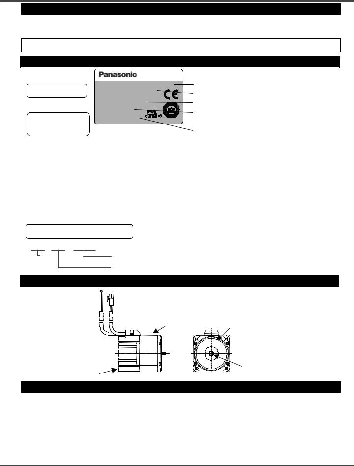
Checking the model of brushless motor
Brushless Motor
Nameplate
Check the
Model Name
Model No. MBMC3A1AXA
Input |
1Ph.100V-120V |
|||||||||
Input Current |
1A |
|
|
|
|
|
||||
|
|
|
||||||||
Ins. Class |
A(UL),E(TUV) |
|||||||||
Rated Output |
30W |
|
|
|
||||||
|
||||||||||
Rated Speed |
3000r/min |
|
|
|
|
|
||||
Rating |
S1 |
|
|
|
|
|
||||
|
IP65 |
|
|
|
|
|
|
|
||
|
|
|
|
|
|
|
||||
Ser. No.
Matsushita Electric Industrial Co. Ltd. Made in Japan C26701
Model name
Rated input voltage Rated output
S1: Continuous rating, S2: Short time rating Serial Number
MBMC 3A 1 A X A |
|
|||||||||||||||||||||||||||
|
|
|
|
|
|
|
|
|
|
|
|
|
|
|
|
|
|
|
|
|
|
|
|
|
|
Set specification (Blank): Console A attached |
||
|
|
|
|
|
|
|
|
|
|
|
|
|
|
|
|
|
|
|
|
|
|
|
|
|
|
|||
Series |
|
name |
|
|
|
|
|
|
|
|
|
|
|
|
|
|
|
|
|
|
|
|
|
P: Console A attached |
||||
|
|
|
|
|
|
|
|
|
|
|
|
|
|
|
|
|
|
|
|
|
||||||||
|
Output |
|
|
|
|
|
|
|
|
|
|
|
|
|
|
|
|
|
|
|
|
|
Function A: Standard |
|||||
|
|
|
|
|
|
|
|
|
|
|
|
|
|
|
|
|
|
|
|
|
|
|||||||
|
|
|
|
|
|
|
|
|
|
|
|
|
|
|
|
|
|
|
|
|
|
Shaft specification |
||||||
|
|
|
|
|
|
|
|
|
|
|
|
|
|
|
|
|
|
|
|
|
|
|||||||
|
3A: 30 W |
|
|
|
|
|
|
|
|
|
|
|
|
|
|
|
|
|
|
|
||||||||
|
|
|
|
|
|
|
|
|
Structure A: Standard |
X: For gear head MX8G |
||||||||||||||||||
|
5A: 50 W |
|
|
|
|
|
|
|
|
|||||||||||||||||||
|
|
|
|
|
|
|
|
|
Z: For gear head MZ9G |
|||||||||||||||||||
|
|
|
|
|
|
|
|
|
||||||||||||||||||||
|
9A: 90 W |
|
|
|
|
|
|
|
|
|
|
|
|
|
Input power supply |
S: Round shaft |
||||||||||||
|
|
|
|
|
|
|
|
|
|
|
|
|
|
|||||||||||||||
1E: 130 W (Rating 30 min) 1: Single phase AC100 – 120 V
Check the Serial Number |
2: Single phase AC200 – 240 V |
|
* 03 11 0001
Manufacturing
year
(Lower 2 digits of Christian Era)
Serial Number |
* Indicates production in November 2003, serial |
Manufacturing month |
number 0001. |
Name of each part
 Power input line
 Connector for control signal
|
Motor unit |
O-ring (not attached in |
|
|
|
||
|
|
specification of round |
|
|
|
shaft) |
|
Control circuit unit |
|
Oil seal |
|
Label of safety precaution is affixed to the product. |
|||
|
|||
Precaution for proper use
1.This motor incorporates control circuit. Control circuit is sensitive to temperature and impact, therefore read this instruction manual carefully for proper installation.
2.This motor is controlled by switching the power element at a high speed.
Therefore, when the motor runs, leaking current may increase, which activates the leakage breaker.
In such a case, use a leakage breaker which is provided with measure against high frequency for inverter.
3.In starting and stopping the motor, use the operation instruction input "I1" or RUN/STOP switch of console A and digital key pad. When the motor is turned on and off by turning on and off power supply, the life of inner circuit may be shortened.
Installation
Installation
Install the brushless motor properly for preventing failure and accident.
Transport
●Use caution enough in transporting the unit to prevent injury by drop or fall, and avoid damage to the equipment.
Storage
●Keep the unit indoors in a clean and dry place free from vibration with little change of temperature.
●In keeping a gear head alone, direct the output shaft down.
(Otherwise, grease leaking is possible.)
Location
●Location gives great influence upon the life of brushless motor, therefore choose a place in conformance with the conditions below:
(1)Indoors where the motor is not subjected to rain water and direct sun beam.
(2)Do not use the motor in corrosive atmosphere such as hydrogen sulfide, sulfurous acid, chlorine, ammonia, sulfur, gas chloride, gas sulfide, acid, alkali, and salt, in the atmosphere of combustible gas, or in the vicinity of flammables.
(3)Place not exposed to grinding liquid, oil mist, iron powder, and cutting particle.
(4)Well-ventilated place with little moisture, oil, or inundation, and place far from heat source such as a furnace.
(5)Place easy to check and clean
(6)Place free from vibration
(7)Do not use the unit in an enclosed environment. Enclosing may raise the temperature of motor, and shorten their life.
Caution in Installing Gear Head
●Idling by damaged tooth, locking by bite, grease leakage, and the like are possible on the life end of gear head. Install a safety device in order to ensure safety even if such trouble should be found.
•Install a device for preventing drop by damaged teeth on a lifter or the like.
•As for application such as opening and closing of door, install a release device against locking by gear biting.
•As for food or textile equipment, install an oil pan for measure against grease leakage.
•Do not install an encoder, sensor, contact, etc in the proximity of gear head. If you should install such devices, take measures against their grease leakage.
•Be sure to perform daily check in order to prevent unexpected accident.
Environmental condition
|
Item |
|
Condition |
|
Ambient |
Brushless motor |
|
-10°C - 40°C (free from freezing) |
*1 |
temperature |
Console A, Digital key pad (optional) |
|
|
|
|
-10°C - 50°C (free from freezing) |
|
||
Ambient humidity |
|
85% RH or below (free from condensation) |
||
Storage temperature |
|
-20°C - 60°C (free from freezing) |
*2 |
|
|
|
|
IP65 (excluding output shaft rotating area, and tip of lead) |
|
Protection |
Brushless motor |
x |
This motor conforms to test condition specified in EN standard (EN60529 and |
|
|
EN60034-5). This motor is not applicable to the use which requires long-term |
|||
structure |
|
|
waterproof performance, such as the case where the motor is always washed |
|
|
|
|
with water. |
|
|
Console A, Digital key pad (optional) |
|
Equivalent to IP20 |
|
|
|
|
||
|
Vibration |
|
Not greater than 4.9 m/s2 (10 – 60 Hz) |
|
|
Altitude |
|
Not greater than 1000m |
|
*1 Ambient temperature is measured at a distance of 5cm from the motor.
*2 Temperature which is acceptable for a short time, such as during transportation.
Installation/System configuration and wiring
Others
●Oil and water protections
(1)Direct down the lead of cable as far as possible.
(2)Avoid use in such an environment where motor is always exposed to oil and water.
(3)Avoid use with cable immersed in oil and water.
●Cable: stress relieving
(1) Make sure that stress is not applied to the lead or connection of cable due to bending or dead weight.
(2)In installation where the motor moves, fix the cable of motor, incorporate the extension cable connected beyond in the cable carrier to reduce stress by bending as small as possible.
(3)Allow the bending radius of cable as large as possible.
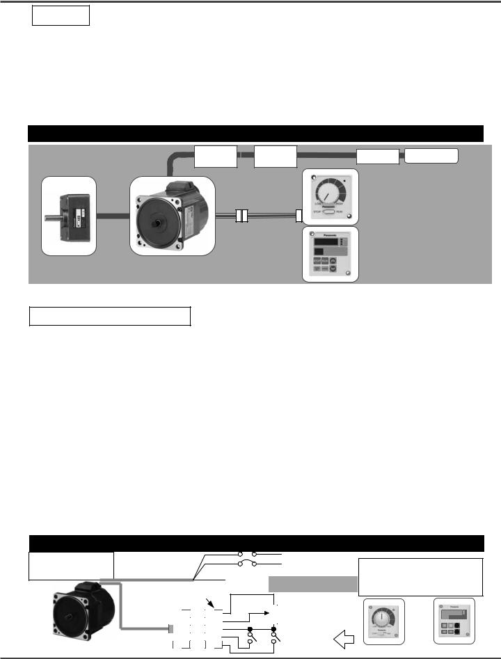
System configuration/general wiring diagram
The lead wire is 0.5m long. |
|
|
Magnetic |
Noise filter |
NFB |
AC power |
|
|
|
contactor |
supply |
||||
|
|
|
|
|
Console A |
||
|
|
|
|
|
(attached, optional) |
||
|
|
|
|
|
It allows switching |
||
|
|
|
|
|
RUN/STOP and CCW/CW |
||
|
|
|
|
|
and setting speed. |
||
|
|
|
Extension cable |
Digital key pad |
|||
|
|
|
(sold separately) |
(sold separately) |
|||
|
|
|
This is a digital display console. |
||||
|
|
|
Connector kit |
||||
Gear head |
B1 Series |
It enables change of parameter. |
|||||
(sold separately) |
(See the use of Digital key pad |
||||||
(sold separately) |
G Type |
||||||
|
|
|
|
|
on page 12 for detail.) |
||
●Wiring work must always be performed by a professional electric worker. |
|
||||||
●Do not turn on power before finishing wiring for avoiding electric shock. |
|
||||||
Selection of wiring equipment |
|
|
|
|
|||
● Recommended noise filter |
Option part number: DVOP3611-5 |
|
(Okaya Electric |
||||
|
|
Manufacturer's part number: SUP-EQ5-ER-6 |
Industries Co., Ltd) |
||||
●Selection of non-fuse breaker (NFB), magnetic contactor (made by Matsushita Electric Works, Ltd), and electric wire (wiring within equipment)
(See "Adaptation to overseas standard" for compatibility with overseas standard.)
Voltage |
Capacity |
NFB (rated current) |
Magnetic contactor |
Electric wire (mm2) |
|
(w) |
(contact structure) |
Main circuit/ |
Control circuit |
||
|
|
Grounding wire |
|||
Single phase 100V |
30 - 90 |
BBC25N(5A) |
BMFT61041N(3P+1a) |
0.5(AWG20) |
0.13(AWG26) |
Single phase 200V |
30 - 130 |
BBC25N(5A) |
BMFT61042N(3P+1a) |
0.5(AWG20) |
0.13(AWG26) |
■ Be sure to ground the grounding terminal.
In wiring to power supply (outside of equipment) from NFB, use an electric wire of 1.6 mm diameter (2.0 mm2) or more both for main circuit and grounding. Apply grounding class D (100
ohms or below) for grounding.
●Selection of relay
As for use for control circuit such as control input terminal, use a relay for small signal (minimum guarantee current 1 mA or less) for preventing poor contact. <Reference example> Matsushita Electric Works, Ltd: DS type, NK type, HC type, OMRON: G2A type
● Control Circuit Switch
When using a switch instead of relay, use one for minute current in order to prevent poor contact. <Example> Nihon Kaiheiki: M-2012J-G
Wiring
Standard |
|
|
|
|
Black |
|
Power input |
Do not tighten the ground |
|
wiring diagram |
<Power input line> |
|
White |
NFB (No-fuse breaker) |
|||||
|
|
wires together, but |
|||||||
|
|
|
|
|
Green/ |
Grounding |
Be sure to ground the |
||
|
|
|
|
|
connect them individually. |
||||
|
|
|
|
|
Yellow |
|
grounding terminal. |
||
|
|
(Connector kit A) |
Rotation |
External speed setting |
|
|
|||
|
|
<Control |
10 |
5 |
5 |
speed |
Variable resistor 5 kΩ |
|
|
|
|
|
B characteristics 1/4 W or |
|
|
||||
|
|
signal connector> |
|
|
|
|
|||
|
|
|
4 Control gland |
above |
|
|
|||
|
|
|
|
|
|
|
|||
|
|
(Motor side) |
|
3 |
|
Operation |
|
|
|
|
|
|
2 |
Rotation |
|
|
|||
Nihon Molex |
|
|
|
|
stop |
|
|
||
|
|
|
|
1 |
direction |
(Console A) |
(Digital key pad) |
||
( ) |
6 |
1 |
|
|
|
||||
39-01-2105 |
5557-10R-210 |
|
|
|
|
|
|||
Wiring/Test run
Function of terminal
<Power input line>
|
Wire color |
|
Name |
Description of function |
|
White/Black (L1, L2) |
|
Power input line |
Connect the terminal to commercial power supply conforming to voltage |
|
|
specification. |
||
|
Green/Yellow (E) |
|
Grounding wire |
Wire for grounding the motor |
<Control signal connector> |
Nihon Molex 39-01-2105 5557-10R-210 |
|||
10 |
5 |
6 |
1 |
(Motor side)
Terminal |
Terminal |
Terminal name |
Description of function |
|
Wire |
|
number |
symbol |
|
color |
|||
|
I1 *1 |
Operation instruction input |
Motor runs when "I1" and "GND" are shorted, and stops when they are opened. |
Brown |
||
|
I2 *1 |
Rotation speed changeover |
CW operation when "I2" and "GND" are shorted, and CCW operation |
*2 |
Red |
|
input |
when they are opened. |
|
||||
GND Control ground |
Common ground terminal for control signal. |
*3 |
|
Orange |
||
|
FIN |
Analog speed |
Speed can be set by applying voltage DC0 – 5V. |
|
Yellow |
|
command input |
Input impedance 100 kΩ. |
|
|
|||
|
|
|
||||
5V |
External speed setting |
Power output dedicated when connecting an external variable resistor |
Green |
|||
power supply |
(5 kΩ, B characteristics) to FIN input (Cannot be used for any other purpose.) |
|||||
|
*1 |
Trip output |
Trip signal output. *1 "L" in trip (Contact ON) |
|
|
Blue |
O1 |
Open collector Vce max: DC30V, Ic max: 50mA |
|
||||
|
|
|
|
|
||
SCK |
|
|
|
|
Purple |
|
|
|
|
|
(Pink) |
||
|
SIN |
Digital key pad I/F |
Interface for digital key pad |
|
|
Gray |
SOT |
|
|
|
|
White |
|
10 (N/A) |
|
(Do not connect anything.) |
|
|
Black |
|
*1 |
Function of input/output can be changed by the Digital key pad. Default is shown. |
*2 |
Rotation direction is that on motor shaft. When gear head is incorporated, the rotation direction of motor and that of gear output shaft |
|
are reversed for some gear reduction ratio. See the allowable shaft torque table on page 8. |
|
(CW: Rotation clockwise when seen from the motor shaft, CCW: Rotation counterclockwise when see from the motor shaft) |
*3 |
When resistor and control GND are disconnected in use of external variable resistor, 5V is input to FIN irrespective of setting of |
|
variable resistor, and upper speed limit is directed; therefore use caution enough for connecting GND. |
■See the optional connector kit A (DVOP3600) for compatible connector.
In extending the control signal wire, keep it below 5m long, and use wire rod above AWG26 (0.12mm2).
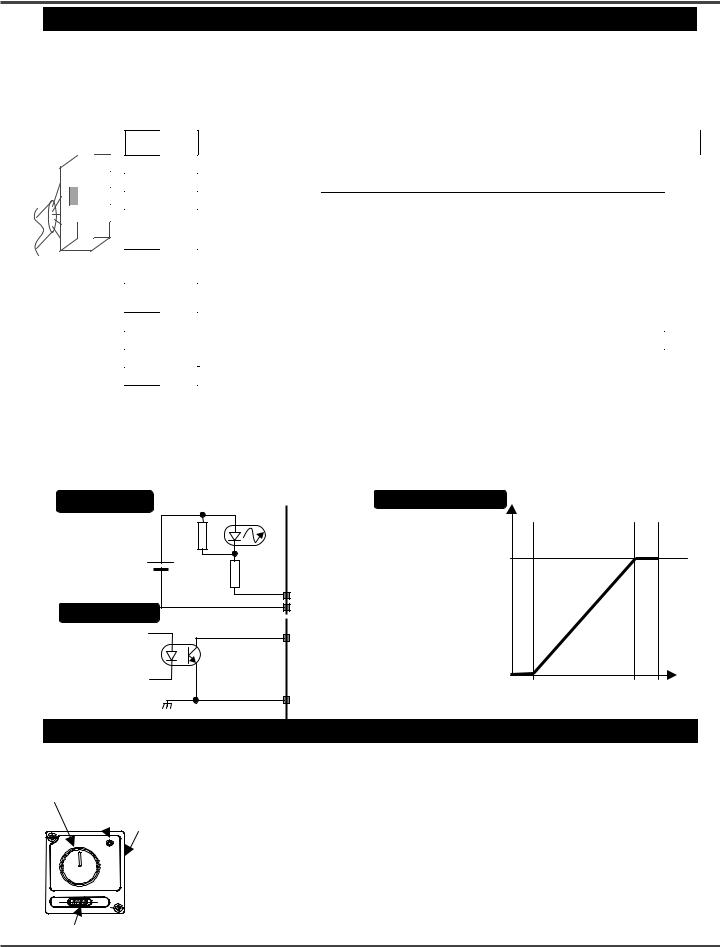
Input circuit
Internal power supply (+5V)
Output circuit
Photo-coupler |
FIN characteristics |
(Typical value) |
|
|||
|
|
|
Preset speed |
|
||
|
|
|
|
|
|
|
|
|
|
(r/min) |
|
|
|
1.5kΩ |
|
|
3000 |
|
|
|
I1, I2 |
(Upper speed limit) |
|
|
|
||
|
|
|
|
|||
|
|
|
|
|
|
|
|
GND |
|
|
|
|
|
|
01 |
|
|
|
|
|
|
Vce max DC30V |
0 |
|
|
|
|
|
Ic max 50mA |
(Lower speed limit) |
0.5V |
4.5V |
5V |
|
|
GND |
|
0V |
|||
|
|
|
|
FIN input voltage |
||
|
|
|
|
|
||
Inspection prior to test run (Console A)
Connect the
Console A
Speed
potentiometer Rotationdirection Power selecting lamp switch
RUN/STOP switch
(Check before operation)
(1) Any mistake found in wiring? (2) Input power supply conforms to rating?
(Test run)
When RUN/STOP switch is changed to RUN, the motor rotates, and when the switch is returned to STOP, the motor stops.
Rotation direction can be changed by rotation direction selecting switch on the side of console. When the rotation direction is changed in RUN, the motor is inverted suddenly, and the motor may trip due to some inertia of load.
Rotation speed can be adjusted by the speed potentiometer. Turn off power when the motor is to be stopped for a long time.
■When power is turned off with RUN/STOP switch on RUN side, and power is turned on again, the motor may start again, which is dangerous. In turning on power, always make sure that the switch is on STOP side.
■When a gear head is incorporated, rotation direction of gear head output shaft may be inverted for some gear reduction ratio. See the table of allowable shaft torque on page 8.
Checking the load and use condition
Check use condition for eternal use of this product. Some use conditions may possibly lead to heating or damage to the shaft. Fully check use conditions, and use the motor in a permissible range.
Standard life
Standard life is 5,000 hours for the motor equipped with gear head (MB8G and MB9G). Standard life is the same 10,000 hours for motor alone (round shaft). (Standard life of sealing performance of oil seal is 5,000 hours.)
Standard life refers to design life for operation 8 hours per day (service factor: Sf = 1.0) at a normal temperature and humidity, under uniform load (permissible shaft torque of gear head and rated torque of motor).
|
Expected of life |
Standard life |
|
Service factor (Sf) |
|||
Service factor (Sf) |
Service factor (Sf) depends on the magnitude of shock of load or operating time. Service factor is shown below for different load conditions:
Type of load |
Example of load |
|
Service factor |
|
|
5 hours/day |
8 hours/day |
24 hours/day |
|||
|
|
||||
Uniform load |
One direction continuous operation |
0.8 |
1.0 |
1.5 |
|
Light shock |
Start, stop, or cam shock |
1.2 |
1.5 |
2.0 |
|
Middle shock |
Instantaneous rotation/reverse rotation and instantaneous stop |
1.5 |
2.0 |
2.5 |
|
Heavy shock |
Middle shock at a high frequency |
2.5 |
3.0 |
3.5 |
Permissible shaft torque
Required shaft torque TA of gear head can be obtained from service factor and actual load torque T1.
TA=T1×Sf
Select a gear head and motor to ensure that required torque (continuous) is within permissible shaft torque in the table below. Here, the torque T1 must not exceed permissible shaft torque TA irrespective of Sf.
Unit: N m
|
Model |
Reduction |
3 |
3.6 |
5 |
6 |
7.5 |
9 |
10 |
12.5 |
15 |
18 |
20 |
25 |
30 |
36 |
50 |
60 |
75 |
90 |
100 |
120 |
150 |
180 |
200 |
|
|
name |
ratio |
||||||||||||||||||||||||
|
MBMC3A□AXA |
0.23 |
0.28 |
0.38 |
0.46 |
0.58 |
0.69 |
0.77 |
0.96 |
1.15 |
1.39 |
1.55 |
1.93 |
2.16 |
2.60 |
3.55 |
4.36 |
5.43 |
6.45 |
6.99 |
7.84 |
7.84 |
7.84 |
|
||
|
MX8G□B |
|||||||||||||||||||||||||
|
MBMC5A□AXA |
0.39 |
0.46 |
0.64 |
0.77 |
0.96 |
1.16 |
1.29 |
1.61 |
1.92 |
2.33 |
2.59 |
3.23 |
3.61 |
4.33 |
5.93 |
7.29 |
7.84 |
7.84 |
7.84 |
7.84 |
7.84 |
7.84 |
|
||
|
MX8G□B |
|||||||||||||||||||||||||
|
MBMC9A□AZA |
0.67 |
0.81 |
1.12 |
1.34 |
1.69 |
2.02 |
2.28 |
2.54 |
3.06 |
3.72 |
4.11 |
5.27 |
6.22 |
6.96 |
9.81 |
11.7 |
14.7 |
17.3 |
19.0 |
19.6 |
19.6 |
19.6 |
19.6 |
||
|
MZ9G□B |
|||||||||||||||||||||||||
|
MBMC1E□AZA |
1.01 |
1.21 |
1.69 |
2.02 |
2.54 |
3.04 |
3.42 |
3.82 |
4.59 |
5.58 |
6.17 |
7.91 |
9.34 |
10.5 |
14.7 |
17.5 |
19.6 |
19.6 |
19.6 |
19.6 |
19.6 |
19.6 |
19.6 |
||
|
MZ9G□B |
|||||||||||||||||||||||||
|
|
|
|
|
|
|
|
* |
Rotation direction is the same as that of motor in shaded portion, and reverse for others. |
|||||||||||||||||
Permissible shaft load |
|
|||||||||||||||||||||||||
|
|
|
|
|
|
|
|
|
|
|
|
|
|
|
|
|
|
|
|
|||||||
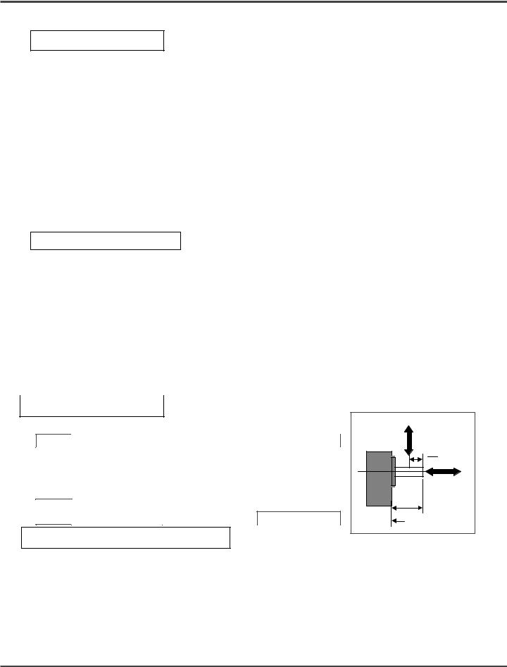
Use the permissible shaft load within the load shown below: |
|
Overhang load |
|||||
|
Model name |
Permissible overhang (w) Permissible thrust (F) |
Motor and |
|
(W) |
||
|
gear head |
|
|
||||
|
MBMC3A□ASA |
100N |
|
10N |
|
L |
|
|
|
|
|
||||
Motor |
MBMC5A□ASA |
100N |
|
10N |
|
|
2 |
|
|
|
|
||||
alone |
MBMC9A□ASA |
150N |
|
20N |
|
|
Thrust load |
|
MBMC1E2ASA |
150N |
|
20N |
|
|
|
|
|
|
L |
(F) |
|||
Gear |
MX8G type |
294N |
|
49N |
|
||
|
|
|
|
||||
head |
MZ9G type |
588N |
|
147N |
|
Mounting surface |
|
Permissible load inertia moment |
Set the acceleration/deceleration time 0.3 seconds or longer. |
||||||
Apply permissible load inertia moment within the value shown below:
(Acceptable value on round shaft applies when stopping operation in free-run stop. In speed reduction stop, the value is 1/4 of indication below only on round shaft due to regeneration. Set a longer speed reduction time if the inertia is not to be lessened. )
Unit: ×10 kg-4 m2
Model |
Reduction |
3 |
3.6 |
5 |
6 |
7.5 |
9 |
10 |
12.5 |
15 |
18 |
20 |
25 |
30 |
36 |
50 |
60 |
75 |
90 |
100 |
120 |
150 |
180 |
200 |
Round |
name |
ratio |
shaft |
|||||||||||||||||||||||
MBMC3A□AXA |
1.25 |
1.79 |
3.42 |
4.90 |
7.72 |
11.2 |
13.8 |
21.6 |
30.6 |
45.2 |
55.8 |
86.9 |
127 |
183 |
342 |
342 |
342 |
342 |
342 |
342 |
342 |
342 |
|
2.5 |
|
MBMC5A□AXA |
|
||||||||||||||||||||||||
MX8G□B |
|
|
|
|
|
|
|
|
|
|
|
|
|
|
|
|
|
|
|
|
|
|
|
|
|
MBMC9A□AZA |
5.93 |
8.47 |
16.4 |
23.6 |
37.3 |
53.4 |
67.6 |
98.3 |
142 |
211 |
257 |
423 |
589 |
847 |
1684 |
1684 |
1684 |
1684 |
1684 |
1684 |
1684 |
1684 |
1684 |
5.6 |
|
MBMC1E□AZA |
|||||||||||||||||||||||||
MZ9G□B |
|
|
|
|
|
|
|
|
|
|
|
|
|
|
|
|
|
|
|
|
|
|
|
|
|
Maintenance and inspections/Assembling of Gear Head
Assembling of Gear Head
●Preparation before assembling
(1)Compatible gear head described on this instruction manual is MX8G□B (for 30, 50W) and MZ9G□B (for 90, 130W). Never combine anything other than compatible gear head in use. Failure to observe this direction may result in malfunction. (□ represents speed reduction ratio.)
(2)Make sure that the O-ring is attached to the bottom of motor flange.
If the gear head is assembled with O-ring floating, it may result in grease leakage.
(3)When grease adheres to the end surface of gear head, wipe off sufficiently.
If the gear head is assembled with grease adhered, it may cause grease to exude.
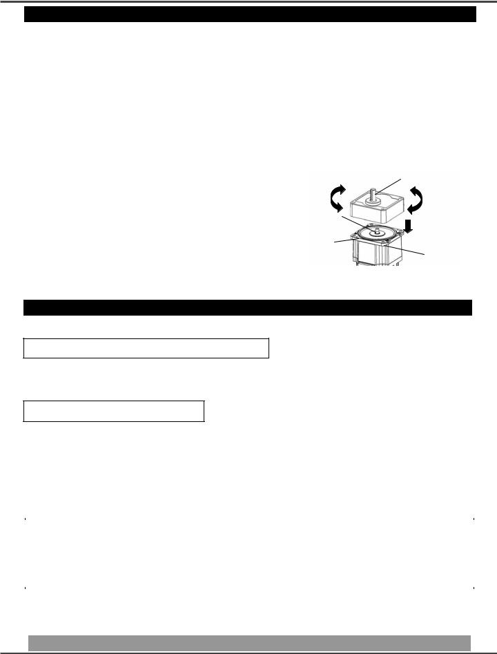
●Assembling
(1)Direct the motor pinion upward, and make sure that the relation between direction of motor lead wire and output shaft matches with the equipment.
(2)Turn the motor pinion finely clockwise and counterclockwise for assembling, ensuring that the tip of motor pinion does not hit the tooth of gear head.
(3)In installing the motor and gear head to the mating equipment, use "mounting screws" attached to the
gear head, tighten them sufficiently to eliminate clearance between the motor flange surface and gear head end surface while paying attention to bite of O-ring. Recommended tightening torque is shown below:
Mounting |
Type of |
Screw |
Tightening torque |
Mounting |
Angle |
gear head |
size |
pitch |
|
dimension |
|
diameter |
||
□80 |
MX8G |
M5 |
2.45N m |
94mm |
|
|
|
|
|
□90 |
MZ9G |
M6 |
2.94N m |
104mm |
|
|
|
|
|
Motor pinion 
O-ring
Output shaft
 Gear head
Flange
Note) Excessive force to assemble the motor and gear, or damage to the tip of motor pinion or tooth of gear head may generate abnormal noise or reduce the life.
Maintenance and inspection
Routine maintenance and inspection are essential for proper and satisfactory operation of the motor.
Notes to Maintenance/Inspection Personnel
●Power-on/off operations should be done by the operators themselves for ensuring safety in checking.
●Do not touch the motor while power on.
●In performing the measuring insulation resistance, remove all connections. Measuring insulation resistance with connection can cause motor failure.
Maintenance/ Inspection item
Maintenance/ |
Inspection |
Condition |
|
Check item |
procedure |
||
|
|||
Input voltage |
Voltmeter |
Must be within ±10% of rating. |
|
|
|
|
|
Input current |
Ammeter |
Must be within rated input current described on nameplate. |
|
|
Insulation |
|
|
Insulation |
Measure the insulation resistance of motor with 500V Megger. It must be above 1Mohm. |
||
resistance |
|||
resistance |
Measuring position: Between power input line (L1, L2) and grounding wire |
||
tester |
|||
|
|
||
|
|
|
|
Noise |
Hearing |
Noise level must not be different from the usual level. In addition, abnormal noise |
|
such as rumbling noise must not be heard. |
|||
|
|
||
|
|
|
|
Vibration |
By hand |
Free from abnormal vibration. |
|
|
|
|
|
Grease |
By sight |
Check that periphery of motor or gear head is not wet by grease or oil. Protect them with |
|
leakage |
a cover etc. in application which is deteriorated by grease leakage. |
||
|
|||
|
|
|
|
Installation |
Torque wrench |
Check for loosening of bolt, and tighten additionally as necessary. |
|
bolt |
|||
|
Check the ambient temperature and humidity, and make sure that dirt, dust, or foreign |
||
Use |
By sight |
||
substance is not found. |
|||
environment |
|||
|
Make sure that the opening of brushless inverter is free from lint. |
||
|
|
Be sure to contact our service division or sales agent for disassembling and repairing of the motor.

Protective functions/How to clear trip
Protective functions
■When the protection function is activated, motor stops and trip signal output turns on. Description of trip can be displayed only when the Digital key pad (option) is connected.
Protection function works even when the Digital key pad is not connected, but it is not displayed.
Protective item |
|
|
|
|
|
Description |
Measure |
Display on |
|
|
|
|
|
|
Digital key pad |
||||
|
|
|
|
|
|
|
|
||
|
When the internal DC voltage is below specified value, |
|
|
||||||
|
operation is stopped; when voltage is recovered, operation |
|
|
||||||
Undervoltage warning |
is started again. (This is not trip, and no trip output is |
|
L |
||||||
(default) |
made.) |
|
|
||||||
|
■Trip can be set by parameter 50. |
Investigate the condition of wiring and circumstances of |
|
||||||
|
100V product: Approx DC100V, |
|
|||||||
|
power supply. |
|
|||||||
|
200V product: Approx DC200V |
|
|||||||
|
|
|
|||||||
|
The motor trips when internal DC voltage is below |
|
|
||||||
Undervoltage error |
specified value only if trip is set by parameter 50. |
|
E-LV |
||||||
100V product: Approx DC100V, |
|
||||||||
|
200V product: Approx DC200V |
|
|
||||||
|
When load factor exceeds specified value, the electronic |
|
|
||||||
Overload warning |
thermal relay operates and monitor display flashes. |
Reduce the load. |
5-digit LED |
||||||
It is a warning for electronic thermal trip. |
|||||||||
(Electronic thermal) |
Check the load factor in monitor mode. |
flashes. |
|||||||
|
|
30-90W: 100% |
|||||||
|
|
|
|
|
|||||
|
|
130W |
: 80% |
Investigate the cause of overload, and reduce the load, |
|
||||
Overload error |
The motor trips when motor torque is output continuously |
|
|||||||
above specified value. |
change the operating pattern by making acceleration |
THr |
|||||||
(Electronic thermal |
|||||||||
|
30-90W: 115% |
and deceleration time longer, or apply design to increase |
|||||||
relay) |
|
130W |
: 105% |
the capacity of motor. |
|
||||
|
|
|
|||||||
|
|
|
|
|
|
|
Excessive acceleration/deceleration setting or gain |
|
|
|
The motor trips when the motor current exceeds specified |
setting is possible. Set the longer |
E-OC |
||||||
Overcurrent error |
acceleration/deceleration time and the smaller gain. |
||||||||
current. |
|
||||||||
|
If this trip should occur as soon as the unit is started, |
||||||||
|
|
|
|
|
|
|
|
||
|
|
|
|
|
|
|
failure is possible. |
|
|
|
|
|
|
|
|
||||
|
The motor trips when internal DC voltage (voltage of |
If the motor should trip in running, too short deceleration |
|
||||||
|
smoothing function of power supply) rises and exceeds |
|
|||||||
|
time is one of the causes. Adjust deceleration time. No |
E-OV |
|||||||
Overvoltage error |
specified value. |
||||||||
measure can be taken in continuous regenerative |
|||||||||
|
Product of 100V: Approx DC200V, |
operation such as lowering. |
|
||||||
|
Product of 200V: Approx DC400V |
|
|||||||
|
|
|
|||||||
User |
Parameter data saved in EEPROM is abnormal. |
Check all parameters again and set them again. If this |
E-UPr |
||||||
parameter error |
protection works frequently, failure is possible |
||||||||
System |
Internal |
parameter data saved in EEPROM is abnormal. |
Failure is possible. |
E-SPr |
|||||
parameter error |
|||||||||
System error |
The motor trips when trouble of control microcomputer is |
Malfunction due to external noise is possible. |
Err |
||||||
detected. |
|||||||||
|
|
|
|
|
|
|
Investigate for noise source in the vicinity and |
|
|
|
|
The motor trips when trouble of CS sensor signal is |
eliminate such source. |
E-CS |
|||||
Sensor error |
|
Internal circuit may be in failure. |
|||||||
|
detected. |
||||||||
|
|
||||||||
|
|
|
|
|
|
||||
|
The motor trips when rotation speed (actual speed) |
Ensure that the actual speed does not exceed rated |
E-OS |
||||||
Overspeed error |
exceeds specified value. |
rotation speed, such as overshooting by unmatching |
|||||||
|
Approx 4500r /min |
between load and gain. |
|
||||||
|
The motor trips when the temperature in control section |
Check the ambient temperature and cooling condition of motor. |
E-OH |
||||||
Overheat error |
rises above specified value. |
Check the load factor. |
|||||||
If the ambient temperature is low enough, and the protection |
|||||||||
|
Approx 105 |
occurs soon after power-on, failure is possible. |
|
||||||
Setting change |
The motor trips when any important parameter such as |
This is not abnormal. Trip reset in order to make change |
CAU |
||||||
warning |
" |
30 |
Run command selection" is changed |
effective. |
|||||
|
|
|
|
|
|
|
|
|
|
How to clear trip
If the motor should trip, eliminate the cause and use any of the procedures [1] – [3] below for clear.
[1] |
Turn off power, and when power LED has gone out, turn on power again. |
||||
[2] |
Press the switch |
>> |
and |
>> |
of the Digital key pad simultaneously for one second or more with present trip |
|
state displayed. |
|
|
|
|
[3] Input the trip reset signal.
(When F-r or r-F is chosen in " 33 I1/I2 function selection", enter "I1" and "I2" at the same time; when F-rST or r-rST is chosen, enter "I2" for trip reset.
Trip reset signal, when continued to be input, is designed to become ineffective in order to prevent inadvertent restarting. Enter trip reset signal only when necessary.)
Note: As for overcurrent error E-OC , sensor error E-CS , System error Err , and user parameter error E-Upr , reset them by turning off power as shown in [1] above. No other procedure is effective.
(Caution) In clear trip, be sure to find and remove the trip factor before clear.
 Loading...