


Live Switcher
Model No. AW-SW350E
ITALIANO FRANÇAIS DEUTSCH ENGLISH
|
|
|
|
|
|
|
|
Live Switcher AW-SW350 |
|
POWER |
|
|
WIPE PATTERN |
|
TRANSITION TIME |
|
|||
|
ON |
|
|
|
|
|
|
|
|
|
|
|
WH1 |
WH2 |
|
WH3 |
AUTO TAKE |
KEY AUTO |
A |
|
OFF |
|
|
|
|
||||
|
|
SF0 |
SF1 |
|
SF2 |
|
|
|
|
|
|
|
YLW |
CYN |
|
GRN |
KEY |
|
|
|
INCOM |
MWR |
INT |
|
FRZ |
|
|
||
|
|
|
|
|
|||||
|
|
|
|
|
|
|
GAIN |
CLIP |
|
|
|
|
MGT |
RED |
|
BLE |
|
|
|
|
LEVEL |
|
|
|
INV |
|
|
|
|
GEN-LOCK PHASE |
|
|
|
|
SOURCE |
KEY AUTO |
|
||
|
SETTING |
COLOR |
|
IN5 |
|
|
|||
H |
SC |
SC FINE |
N |
|
|
|
|||
|
|
|
|
|
|||||
|
|
|
|
|
|
N / R |
FMEM |
|
|
|
|
|
|
|
|
R |
|
|
|
|
|
|
|
|
|
|
|
|
|
|
|
|
|
A |
|
FRZ |
MIX |
|
|
|
|
|
|
|
|
|
|||
|
|
|
|
|
|
|
|
|
|
|
|
|
|
|
|
|
WIPE |
|
|
1 |
|
2 |
3 |
|
4 |
5 |
BLACK |
|
|
|
|
FMEM |
COLOR |
|
|
||||
|
|
|
|
|
|
BAR |
|
|
|
|
|
|
|
|
|
|
AUTO |
TAKE |
B |
|
|
|
|
|
|
|
|
|
|
B
ESPAÑOL
Before attempting to connect, operate or adjust this product, please read these instructions completely.

$ DO NOT REMOVE PANEL COVER BY UNSCREWING.
To reduce the risk of electric shock, do not remove cover. No user serviceable parts inside.
Refer servicing to qualified service personnel.
WARNING:
TO REDUCE THE RISK OF FIRE OR SHOCK HAZARD, KEEP THIS EQUIPMENT AWAY FROM ALL LIQUIDS-USE AND STORE ONLY IN LOCATIONS WHICH ARE NOT EXPOSED TO THE RISK OF DRIPPING OR SPLASHING LIQUIDS, AND DO NOT PLACE ANY LIQUID CONTAINERS ON TOP OF THE EQUIPMENT.
CAUTION:
TO REDUCE THE RISK OF FIRE OR SHOCK HAZARD AND ANNOYING INTERFERENCE, USE THE RECOMMENDED ACCESSORIES ONLY.
CAUTION:
TO REDUCE THE RISK OF FIRE OR SHOCK HAZARD, REFER CHANGE OF SWITCH SETTING INSIDE THE UNIT TO QUALIFIED SERVICE PERSONNEL.
Note:
The rating plate (serial number plate) is on the bottom of the unit.
indicates safety information.
The information marking of this product may be found on the bottom of the unit. The serial number of this product may be found on the bottom of the unit.
You should note the serial number of this unit in the space provided and retain this book as a permanent record of your purchase to aid identification in the event of theft.
Model No.
Serial No.
2 (E)

CONTENTS
WARNING/CAUTION FOR SAFETY ..................................................................................... |
4 |
PREFACE .............................................................................................................................. |
5 |
FEATURES ........................................................................................................................... |
6 |
PRECAUTIONS ..................................................................................................................... |
7 |
MAJOR OPERATING CONTROLS AND THEIR FUNCTIONS ............................................ |
8 |
■TOP (CONTROL PANEL) ........................................................................................ |
8 |
■REAR PANEL ........................................................................................................ |
15 |
IMAGE TRANSFER FUNCTION ......................................................................................... |
20 |
■FUNCTIONS .......................................................................................................... |
20 |
■SPECIFICATIONS ................................................................................................. |
21 |
■INSTALLING THE DEVICE DRIVER ..................................................................... |
22 |
■INSTALLING THE APPLICATION PROGRAMME ................................................ |
25 |
■OPERATION METHOD ......................................................................................... |
27 |
CONNECTIONS .................................................................................................................. |
32 |
■CONNECTION WITHOUT EXTERNAL SYNCHRONIZATION ............................. |
32 |
■CONNECTION FOR EXTERNAL SYNCHRONIZATION ...................................... |
33 |
■CONNECTION TO PERSONAL COMPUTER ...................................................... |
34 |
■EXAMPLE FOR THE CONNECTION |
|
WITH PAN/TILT HEADS AND CONTROL PANEL ............. |
36 |
RACK MOUNTING .............................................................................................................. |
38 |
■RACK MOUNTING ................................................................................................ |
38 |
INFORMATION RELATED TO SYSTEM UPGRADES ...................................................... |
39 |
SPECIFICATIONS/STANDARD ACCESSORIES .............................................................. |
40 |
■SPECIFICATIONS ................................................................................................. |
40 |
■STANDARD ACCESSORIES ................................................................................ |
41 |
ENGLISH
3 (E)

WARNING/CAUTION FOR SAFETY
 WARNING
•Refer all servicing to qualified personnel
To reduce the risk of electric shock, don't remove cover or back, unless you are a qualified personnel. Refer all mountings, connections, servicing to qualified service personnel.
•No water or moisture inside
Do not let water or moisture into the product, or expose it to moisture, to prevent a fire and electric shock.
•If you see smoke or smell an odor from the product, if water or other foreign matter gets inside, if it is damaged by dropping, or if you find anything wrong with it, immediately stop using it.
•Do not disassemble or modify the product to prevent a fire and electric shock.
 CAUTION
•Do not drop the product, do not expose it to strong shock, or do not step on it, to prevent a fire and injuries.
•Do not install the product at a place full of moisture and dust, which may cause a fire and electric shock.
•Do not mount the Live Switcher on a closed rack or bookshelf. (Otherwise, heat will build up inside and may cause a fire.)
•Keep the ventilation port open to secure good flow of air.
PREFACE
The AW-SW350 has five video inputs, wipe, mix and key synthesis functions despite its compact dimensions. Since it has a built-in frame synchronizer, it accepts the input of asynchronous signals. Moreover, it enables systems to be configured using the black burst signals which it outputs, and it supports external synchronization (or genlock) to external sync signals as well. Its image transfer function enables the images and text created using a personal computer to be captured in the switcher through its USB port. The switcher can be used in the field because it operates on an external power supply (12 V DC) while its tally outputs and intercom inputs/outputs permit easy system configuration.
ENGLISH
4 (E) |
5 (E) |

FEATURES
•Five Inputs Despite Compactness
The switcher has five composite video signal inputs. (Automatic termination. Loopthrough output provided) It also has an S-terminal (4-pin), and can thus handle YC signals. Input 5 can be switched to the internal frame memory or vice versa by means of a switch. Internal black or colour signal (9 patterns) can be selected.
•Three Programme Outputs, Preview Outputs Available
Effect outputs including two composite video outputs (BNC connectors) and one YC signal output (S-terminal, 4-pin) are available, so it is easy to build a system with monitors, VTRs, etc. The AW-SW350 also features the Preview output to confirm the next operation. (Look Ahead Preview)
•Frame Synchronizer System and Genlock System Supported
The switcher contains a high-performance 10-bit frame synchronizer: this means that asynchronous signals can be directly input to the input camera or other such device without having to initiate genlock. Its inputs are equipped with a frame synchronizer function so that its images are do not freeze even when the frames are switched. Alternatively, the frame synchronizer can be turned off, genlock can be applied to a camera or other such device, and the unit can be used as a wideband switcher with minimal deterioration in image quality (resolution of 800 lines).
•Genlock
The switcher enables genlocking to the reference sync signal of an external device. Furthermore, by using its BB output, the system can be upgraded using the synchronization of the switcher as a reference.
•Image Transfer, Soft Keys and Linear Keys
Inside the switcher AW-SW350 has a 1-frame frame memory so that the images created using a personal computer can be captured in this memory through the USB port. There are nine different patterns for wipe, and one of three softness levels can be set. Text can also be synthesized smoothly by performing linear key operations.
•External Power Supply
The switcher can be used both indoors and outdoors because it operates on an external power supply of 12 V DC.
(However, it is not built rainproof or dripproof. Do not expose the switcher to rains or moisture.)
•Tally and Intercom Provided
Five tally outputs and five intercom inputs and outputs are available so that the switcher can be directly apply to conventional systems. (The switcher has its own intercom on the panel.)
PRECAUTIONS |
|
ENGLISH |
||
• |
Handle with Care. |
|||
|
||||
|
Do not drop the switcher, or expose it to strong shock or vibration. This is important to |
|
||
|
|
|||
|
prevent trouble and accidents. |
|
||
• |
Operating temperature range 0˚C to 40˚C |
|
||
|
Avoid using it in a cold place below 0˚C or a hot place above 40˚C because low or high |
|
||
|
temperature will adversely affect the parts inside. |
|
||
• |
Switch power off before cables connection or disconnection. |
|
||
|
Be sure to switch power off before connecting or disconnecting the cables. |
|
||
• |
Use at a Place Not Humid, Not Dusty. |
|
||
|
Avoid using the switcher at a humid, dusty place because the internal parts are subject to |
|
||
|
damage by moisture and dust. |
|
||
• |
Care |
|
||
|
Switch power off and wipe the switcher with a dry cloth. If it is difficult to remove the dirt, |
|
||
|
dip a cloth into a diluted solution of kitchen detergent, squeeze it hard, and wipe the |
|
||
|
product carefully. |
|
||
Note
•Do not use benzine, paint thinner, or other volatile liquids.
•When using a chemical duster, carefully read the caution notes on its use.
6 (E) |
7 (E) |
MAJOR OPERATING CONTROLS AND THEIR FUNCTIONS
■TOP (CONTROL PANEL)
|
|
|
|
|
Live Switcher AW-SW350 |
|
POWER |
|
WIPE PATTERN |
|
TRANSITION TIME |
|
|
ON |
|
|
|
|
|
|
|
WH1 |
WH2 |
WH3 |
AUTO TAKE |
KEY AUTO |
A |
OFF |
|
|
||||
S F 0 |
S F 1 |
S F 2 |
|
|
|
|
|
|
|
|
|||
|
YLW |
CYN |
GRN |
KEY |
|
|
INCOM MWR |
I N T |
F R Z |
|
|
||
|
|
|
||||
GAIN CLIP
|
|
MGT |
RED |
BLE |
|
|
|
|
LEVEL |
|
I N V |
|
|
|
|
GEN-LOCK PHASE |
|
|
SOURCE |
KEY AUTO |
|
||
SETTING |
COLOR |
IN5 |
|
|
|||
H |
SC |
SC FINE |
|
|
|
||
|
N |
|
|
|
|||
|
|
|
|
|
|
|
|
|
|
|
|
N / R |
FMEM |
|
|
|
|
|
|
R |
|
|
|
|
|
|
|
|
|
|
|
|
|
|
A |
FRZ |
MIX |
|
|
|
|
|
|
|
|||
|
|
|
|
|
|
|
|
|
|
|
|
|
WIPE |
|
|
1 |
2 |
3 |
4 |
5 |
BLACK |
|
|
FMEM |
COLOR |
|
|
||||
|
|
|
|
BAR |
|
|
|
|
|
|
|
|
AUTO |
TAKE |
B |
|
|
|
|
|
|
|
|
|
|
|
B |
|
|
|
|
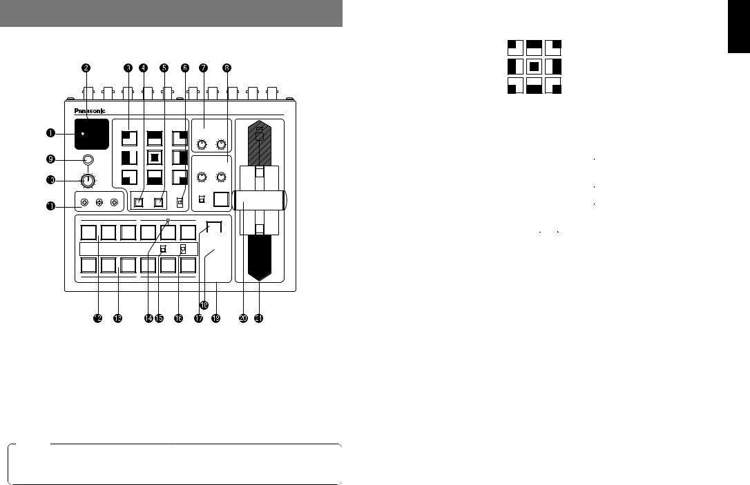
QPower Indicator [POWER]
Lights (green) when power is supplied to DC Power Input Terminal L and Power Switch W set to the ON position, and goes out when Power Switch W is set to the OFF position.
WPower Switch [POWER ON/OFF]
Power is switched on and Power Indicator Q lights when this switch is set to the ON position, provided that power is supplied to DC Power Input Terminal L. Power is switched off and Power Indicator Q goes out when the switch is set to the OFF position.
Caution
Even when the Power Switch is at the OFF position, some of the power supply circuits are still operating. To turn off the power completely, set the external power adaptor to OFF.
EWipe Pattern Selection Switches [WIPE PATTERN]
To select a wipe pattern after pressing Wipe Switch y. One of the nine patterns can be selected. The selected switch lights.
ENGLISH
RSetting Switch [SETTING]
This functions as the shift key for the wipe patterns. While it is held down, the Wipe Pattern Selection Switches can select the functions described below. The functions are indicated with blue characters.
SF0 |
|
|
SF1 |
|
|
|
SF2 |
|
|
|
|
|
|
|
|
||||
|
|
|
|
|
|
|
|
||
MWR |
|
|
INT |
|
|
|
FRZ |
|
|
|
|
|
|
|
|
|
|||
|
|
|
|
|
|
||||
|
|
|
|
|
|
|
INV |
|
|
|
|
|
|
|
|
|
|
|
|
|
|
|
|
|
|
|
|
|
|
SF0, SF1, SF2: These are used to set the three wipe softness levels.
The minimum softness level is set by SF0 (a hard key), and the maximum softness level is set by SF2.
MWR: |
This makes it possible for the user to set the initial statuses of the panel |
|
when the power is turned on. |
|
First, set the statuses of the panel to be recorded. Once the setting has |
|
been performed, keep pressing MWR while holding down the SETTING |
|
switch until the nine switches go off. The recorded statuses will be |
|
reproduced when the power is next turned on. |
INT: |
This is used to restore the initial settings which were established at the |
|
factory. |
|
Keep pressing INT while holding down the SETTING switch until the nine |
|
switches go off. The same statuses as the factory setting statuses will be |
|
established when the power is next turned on. |
FRZ: |
This is used to set the freezing of the Video Input 5 signal to ON or OFF. |
|
When FRZ is pressed while holding down the SETTING switch, the Video |
|
Input 5 signal is frozen. While the signal is frozen, the FRZ w LED lights. |
|
This signal can be used as the source of the VIDEO IN 5 signal. |
|
If the freeze function is used while the FS switch is in the OFF position, |
|
only the Video Input 5 signal will be set to the FS ON status. |
8 (E) |
9 (E) |

INV: |
This is used to invert the polarity of the key signal. |
|
Use the inversion mode when the input is black text on a white base. |
|
When the INV function is used with VIDEO IN 5 selected for the key |
|
source and with the FS switch in the OFF position, only the Video Input 5 |
|
signal will be set to the FS ON status. |
TColour Background Colour Selector Switch [COLOR]
This functions as the shift key of the Wipe Pattern Selection Switches. While it is pressed, the Wipe Pattern Selection Switches can select the colour to be used for the colour background, as shown below. The functions are indicated with red characters.
WH1 |
|
|
WH2 |
|
|
|
WH3 |
|
|
YLW |
|
|
CYN |
|
|
|
GRN |
|
|
|
|
|
|
|
|
|
|||
|
|
|
|
|
|
|
|||
|
|
|
|
|
|
||||
MGT |
|
|
RED |
|
|
|
BLE |
|
|
|
|
|
|
|
|
|
|||
|
|
|
|
|
|
|
|||
|
|
|
|
|
|
|
|||
|
|
|
|
|
|
|
|
|
|
|
|
|
|
|
|
|
|
|
|
WH1: |
White 100% |
WH2: |
White 90% |
WH3: |
White 80% |
YLW: |
Yellow |
CYN: |
Cyan |
GRN: |
Green |
MGT: |
Magenta |
RED: |
Red |
BLE: |
Blue |
YWipe Direction Selection Switch [N/ N/R/ R]
To select one of the three directions in which to change the signals from A to B or vice versa on the screen by moving Fader Lever i.
N (Normal):
When Fader Lever i is moved from A to B, the image is switched from the selected A-bus signal to the selected B-bus signal in the direction of the black to white pattern shown on Wipe Pattern Selection Switch. Similarly, when Fader Lever i is moved from B to A, the image on the screen is switched from the selected B-bus signal to the selected A-bus signal.
R (Reverse):
When Fader Lever i is moved from A to B, the image is switched from the selected A-bus signal to the selected B-bus signal in the direction of the white to black pattern shown on Wipe Pattern Selection Switch. Similarly, when Fader Lever i is moved from B to A, the image on the screen is switched from the selected B-bus signal to the selected A-bus signal.
N/R (Normal/Reverse):
When Fader Lever i is moved from A to B, the image is switched from the selected A-bus signal to the selected B-bus signal in the direction of the black to white pattern shown on Wipe Pattern Selection Switch. When Fader Lever i is moved from B to A, the image on the screen is switched from the selected B-bus signal to the selected A-bus signal.
[Example] Selected wipe pattern
Fader lever |
Normal (N) |
Reverse (R) |
Normal/Reverse (N/R) |
ENGLISH |
||||||||||||||||||||||
|
||||||||||||||||||||||||||
A |
|
|
|
|
|
|
|
|
|
|
|
|
|
|
|
|
|
|
|
|
|
|
|
|||
|
|
|
|
|
|
|
|
|
|
|
|
|
|
|
|
|
|
|
|
|
|
|
||||
|
|
|
|
|
A |
B |
|
|
B |
|
A |
|
|
A |
|
B |
|
|
||||||||
|
|
|
|
|
|
|
|
|
|
|
|
|
||||||||||||||
|
|
|
|
|
|
|
|
|
|
|
|
|
||||||||||||||
|
|
|
|
|
|
|
|
|
|
|
|
|
|
|
|
|
|
|
|
|
|
|
|
|
|
|
B |
|
|
|
|
|
|
|
|
|
|
|
|
|
|
|
|
|
|
|
|
|
|
|
|||
A |
|
|
|
|
|
|
|
|
|
|
|
|
|
|
|
|
|
|
|
|
|
|
|
|||
|
|
|
|
|
|
|
|
|
|
|
|
|
|
|
|
|
|
|
|
|
|
|
|
|
|
|
|
|
|
|
|
B |
A |
|
|
A |
|
B |
|
|
A |
|
B |
|
|
||||||||
|
|
|
|
|
|
|
|
|
|
|
|
|
||||||||||||||
|
|
|
|
|
|
|
|
|
|
|
|
|
||||||||||||||
B |
|
|
|
|
|
|
|
|
|
|
|
|
|
|
|
|
|
|
|
|
|
|
|
|||
|
|
|
|
|
|
|
|
|
|
|
|
|
|
|
|
|
|
|
|
|
|
|
||||
UTransition Time Setting Controls [TRANSITION TIME]
These controls are used to set the transition time during auto fader operations. AUTO TAKE: This is used to set the transition time of MIX or WIPE when the AUTO
TAKE u Switch has been pressed. Any transition time from 0 to about 10 seconds can be set.
KEY AUTO: This is used to set the transition time when the KEY AUTO I Switch has been pressed. Any transition time from 0 to about 5 seconds can be set.
Turning either control knob counterclockwise reduces the transition time; conversely, turning them clockwise increases the transition time. When either control knob is turned counterclockwise as far as it will go, the transition time is set to 0 seconds, and the cut operation results. Even when external takes are performed using external switches, the settings of these controls remain in force. (When a switch has been connected to EXT TAKE H)
Caution
Before proceeding with auto fader operations, set the transition times in advance using these controls.
IKey Synthesis Setting Controls [KEY]
These are used to perform the settings relating to key synthesis.
GAIN, CLIP: The AW-SW350 features a linear key system for key synthesis to ensure smooth synthesis, and these two controls are used to set the synthesis levels when text and other data are to be synthesized with the key signals. The CLIP control is for setting the reference level at which the key signals are to be created, and signals above this level are synthesized. If noise is present in the background images, set the CLIP level on the high side. The GAIN control is for raising or lowering the level of the key signals. Adjust it in such a way that the text, etc. can be synthesized cleanly and clearly.
[Example of adjustment]
Turn the CLIP control counterclockwise as far as it will go and, while viewing the screen, adjust the GAIN control to achieve clean and clear images. Next, adjust the CLIP and GAIN controls alternately to set to the optimum state.
10 (E) |
11 (E) |

KEY AUTO: |
This switch is used to set the key synthesis to ON or OFF. |
|
When it is pressed, it lights, and key synthesis is performed for the text, |
|
etc. KEY AUTO U is used to set the transition time for the key synthesis. |
|
When the switch is pressed again, it goes off, and the input signals used |
|
for the key synthesis will be synthesized as they are with the base image |
|
but, depending on the level of the input signals, it may not be possible to |
|
achieve clean and clear images. |
SOURCE: |
This selects whether to use the VIDEO IN 5 signal or image in the frame |
|
memory as the source material for the key synthesis. In terms of the key |
|
signals, use black base level signals, and provide a source with white |
|
characters. |
|
A source with colour characters can also be synthesized with a black base |
|
but, depending on the level of the character signals, it may not be possible |
|
to achieve clean and clear images. |
|
(By inverting the polarity of the key signals, images with a white base level |
|
can also be synthesized. For details on key reversal, refer to SETTING R.) |
Note
Follow the procedure below to keep the key synthesis on the PVW screen at the OFF setting at all times.
1.Press both the SETTING Button R and COLOR Button T at the same time.
2.With the two buttons in step 1 held down, press the KEY AUTO Button. The KEY AUTO Button lamp now lights.
To turn the key synthesis on the PVW screen back to the ON setting, repeat the same steps. The KEY AUTO Button lamp will then go off.
OIntercom Jack [INCOM]
Connect an intercom headset to this terminal. Use the recommended headset (made by Ashida Onkyo MT-12MFB-03).
PIntercom Volume [INCOM LEVEL]
To adjust the volume of the headset speaker connected to Intercom Jack O. Turning it counterclockwise decreases the volume, and turning it clockwise increases it.
{Genlock Phase Controls [GEN-LOCK PHASE]
Connect a signal generator or other such instrument to GLIN/BBOUT D, and use these
controls to adjust the phase when genlock is to be initiated. These controls need not be adjusted when genlock is not going to be initiated.
H:This is used to adjust the horizontal sync phase.
SC: This is used to adjust the subcarrier phase coarsely.
SC FINE: This is used to adjust the subcarrier phase finely.
Adjusting the horizontal phase:
Monitor the waveforms of the genlock signal (black burst signal) and video signal output using a dual-trace oscilloscope (or waveform monitor), and adjust the H Control in such a way that the horizontal phase is aligned.
Adjusting the subcarrier phase:
Select the colour bars of the switcher. Using the signal generator as a reference, adjust the SC Control and SC FINE Control to align the colour phase. A more accurate adjustment can be achieved using a vectorscope.
}A-Bus Input Selection Switches
To select A-bus video signals. When a switch is pressed, it lights and indicates that the corresponding signal is selected.
qB-Bus Input Selection Switches
These are used to select the B-bus video signals. When a switch is pressed, it lights to indicate that the corresponding signal is selected.
Depending on the operation mode, the switches may light with full or half brightness. Full brightness: When the selected input is being output to PGM OUT.
Half brightness: When the switch is selected but the selected input is not being output to PGM OUT.
[Example] When the Fader Lever is at the A-bus side, the A-bus signals are output so that the A-Bus Input Selection Switches will light with full brightness, but the B- bus signals are not output so that B-Bus Input Selection Switches will light with half brightness.
wFreeze indicator [FRZ]
This LED lights to indicates that the VIDEO IN 5 signal is frozen. Bear in mind that since the image remains frozen while it is lit, the switcher output will not change even when the input signal has changed.
eInput 5/FMEM Selector Switch [FMEM]
This is used to select the signal which has been input to VIDEO IN 5 or the internal frame memory. When the switcher is used for the first time and the frame memory has been selected, the factory setting screen is output. By transferring image data from a personal computer to the frame memory, the images and text created by the user can be output. For details, refer to the page on which image transfer is described.
rBLACK/COLOR/BAR Selector Switch [BLACK/COLOR/BAR]
This is used to select BLACK (black level signal), COLOR (colour background) or BAR (colour bar). When COLOR is selected, one of nine colours can be selected. For details on how to select the colour, refer to the section on “T Colour Background Colour Selector Switch [COLOR]”.
A 100% white signal is output at the factory setting.
ENGLISH
12 (E) |
13 (E) |
tMix Switch [MIX]
Press it to switch the signal selected with A-Bus Input Selection Switch } to the signal selected with B-Bus Input Selection Switch q or vice versa by the mix effect. The switch lights when MIX is selected.
yWipe Switch [WIPE]
Press it to switch the signal selected with A-Bus Input Selection Switch } to the signal selected with B-Bus Input Selection Switch q or vice versa by the wipe effect. The switch lights when WIPE is selected.
uAuto Take Switch [AUTO TAKE]
This switch is used for automatically wiping or mixing instead of performing these operations manually using the Fader Lever i. This switch becomes operational when the Fader Lever i is set all the way toward the A or B side, and when it is pressed once, the wipe or mix operation is performed automatically. The transition time for switching the signals can be adjusted using the AUTO TAKE U control. While the signals are being switched, the AUTO TAKE switch lights, and it goes off when the signals are switched completely. During an auto take operation, no manual operations will be performed even if the Fader Lever i is moved.
Caution
In using the Auto Take function, be sure to move Fader Lever i all the way to A or B. Auto Take will not work unless the lever is fully moved to A or B.
iFader Lever [A/B]
This lever is used to switch the signal selected with A-Bus Input Selection Switch } to the signal selected with B-Bus Input Selection Switch q or vice versa by the wipe or mix effect. When the lever is moved from A to B, the video signal is also switched from A to B accordingly. Similarly, when the lever is moved from B to A, the video signal is switched from B to A.
oBus Tally Indicators [A], [B]
These indicate the output statuses of the A-bus and B-bus. The [A] or [B] LED lights to indicate that A-bus or B-bus signals are being output.
[Examples] • [A] lights when the Fader Lever is at the A side since only the A-bus signals are output.
•Both [A] and [B] light when the Fader Lever is between the A and B sides since both A-bus and B-bus signals are output.
Note
Bus control based on the flip-flop system is enabled by changing the setting of the bus selector switch [BUS A/B /F.F.]R which is one of the Setup Switches K. Under the flipflop system, the signals selected by the A-Bus Input Selection Switches } are always selected as the programme (PGM) video signals, and the signals selected by the B-Bus Input Selection Switches q are always selected as the preview (PVW) video signals. Furthermore, the PGM signals can be replaced with the PVW signals or vice versa by means of bus switching using the AUTO TAKE Switch u and Fader Lever i.
■REAR PANEL
ENGLISH
BBOUT |
GLIN |
|
|
|
PVW |
|
PGM OUT |
|
|
VIDEO |
|
|
|
/BBOUT |
|
|
|
OUT |
2 |
1 |
5 |
4 |
3 |
2 |
1 |
|
|
|
|
|
|
|
|
|
|
|
|
IN |
|
|
TALLY & INCOM |
|
|
|
|
|
|
75Ω |
|||
5 |
4 |
|
|
|
3 |
|
2 |
1 |
|
|
|
AUTO |
|
|
|
|
|
|
|
|
|||||
|
|
|
|
|
|
|
|
|
|
|
|
OUT |
|
|
|
|
|
|
|
|
PGM |
|
Y / C IN |
|
|
|
DC 12V IN |
|
|
|
|
|
EXT |
|
|
|
|
|
|
|
|
|
USB |
|
Y / C |
|
|
|
|
||
|
SET UP |
|
TAKE |
OUT |
|
|
|
|
||||
|
1 |
2 |
3 |
4 |
|
|
|
|
|
|
|
|
|
|
|
|
|
|
|
|
5 |
4 |
3 |
2 |
1 |
GND
pVideo Signal Input Jacks 1 to 5 [VIDEO IN 1, 2, 3, 4, 5]
These jacks are to input composite video signals. (1 Vp-p, 75-ohm auto-terminated) There are 5 input jacks corresponding to A-Bus Input Selection Switches } and B-Bus Input Selection Switches q.
Caution
If a BNC coaxial cable is connected to Video Signal Loopthrough Output Jack [, the 75-ohm termination is automatically released. Do not connect a BNC coaxial cable to any of these jacks in case of connecting YC signals to Y/C Signal Input Jack ]. Use either composite signals or YC signals as video input signals.
Furthermore, when unstable video signals from a VHS format VTR, DVD player or other device have been input, the frame synchronizer may malfunction.
[Video Signal Loopthrough Output Jacks [VIDEO OUT 1, 2, 3, 4, 5]
These loopthrough output jacks are for the composite video signals input to Video Signal Input Jacks p.
14 (E) |
15 (E) |
]Y/C Signal Input Jacks [Y/C IN 1, 2, 3, 4, 5]
Connect YC signals to these jacks in using them as video input signals.
Caution
Do not connect a BNC coaxial cable to Video Signal Input Jack p in case of connecting YC signals to Y/C Signal Input Jack ]. Use either composite signals or YC signals as video input signals.
4 |
3 |
Pin No. |
Signal |
|
1 |
Y GND |
|||
2 |
1 |
|||
2 |
C GND |
|||
|
|
|||
|
|
3 |
Y |
|
|
|
4 |
C |
AVideo Output Connectors [PGM OUT 1, 2]
Two sets of composite signals (BNC) consisting of the switcher's main output together with the wipe, mix, key or other effects added are output from these output jacks.
SPreview Output Connector [PVW OUT]
When the switcher is used for live applications, this connector enables the next operation to be previewed. (LOOK AHEAD PREVIEW)
•While the Fader Lever is at the A-bus side and A-bus signals are output, the B-bus signals are output to the PVW OUT Connector, and the images can be previewed.
•When the PGM OUT Connectors are in the key OFF status, the PVW OUT Connector is set to the key ON status and the key synthesis status can be previewed.
The table below shows the correlation between the programme output and preview output statuses.
|
Bus selection |
Key ON/OFF |
||
PGM OUT |
A-bus selected |
B-bus selected |
Key ON |
Key OFF |
PVW OUT |
B-bus output |
A-bus output |
Key OFF |
Key ON |
DGenlock Input/BB Output Connector [GLIN/BBOUT] |
ENGLISH |
|
Genlock input: To apply genlock to the switcher, connect this signal to the signal |
||
In compliance with the setting of the SETUP switch K, either the genlock input or BB |
|
|
output is selected. |
|
|
|
generator or other device. |
|
BB output: |
At this position, the BB sync signal is output to apply genlock to a camera |
|
|
or other input device by synchronizing it to the switcher. In this case, the |
|
|
same signal as BBOUT F is output. |
|
FBlack Burst Signal Output Connector [BBOUT]
Used to externally synchronize a input device connected to the Live Switcher. When externally synchronizing two or more devices, distribute the black burst output to them using a video distributor (VDA).
GY/C Video Output Connector [PGM Y/C OUT]
This connector delivers the Y/C signal video output which has the same function as the video output signal A.
Caution
Due to what is involved in the signal processing, the Y/C video output G has a phase which is delayed by 1 line compared with the composite video output A.
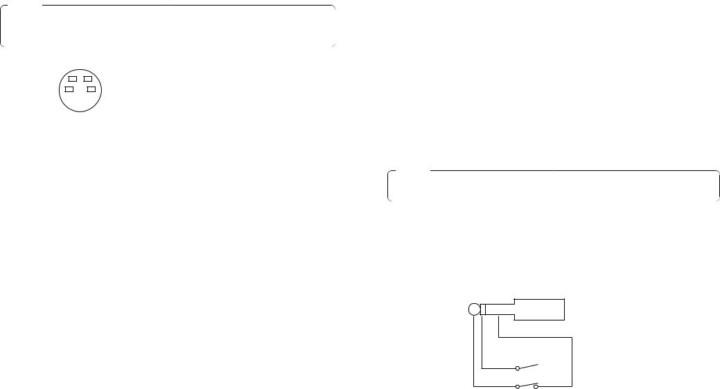
HAuto Take External Input Jack [EXT TAKE]
Use it for external auto take by applying a contact input. The operation is the same as when using Auto Take Switch u and Key Auto Switch I.
Use an M3.5 stereo single head plug for connection with this unit.
Connect the switches as shown below.

 AUTO TAKE
KEY AUTO
16 (E) |
17 (E) |
JUSB port [USB]
Connect one end of the USB cable to this port and the other end to the personal computer to transfer the image data created by the personal computer to this switcher. For details, refer to the page on which image transfer is described.
KSetup switches
These are used to perform the following four settings.
ON |
BBOUT |
3-wire |
A/B |
|||||||||
type |
||||||||||||
|
|
|
|
|
|
|
|
|
|
|
|
|
|
|
|
|
|
|
|
|
|
|
|
|
|
|
|
|
|
|
|
|
|
|
|
|
|
|
OFF |
GLIN |
4-wire |
F.F. |
|||||||||
type |
||||||||||||
|
|
|
|
|
|
|
|
|
||||
|
|
|
|
|
|
|
|
|
|
|
|
|
FS |
GLIN |
INCOM |
BUS |
|||||||||
|
|
|
/BBOUT |
|
|
|
|
|
|
|||
QFrame Sync Switch [FS ON/OFF]
This sets the frame synchronizer to ON or OFF.
ON: The asynchronous 5 input signal can be connected. A delay of up to one frame is generated in the switcher output. Due to what is involved in the signal processing, the signal band is narrower than at the OFF position.
OFF: The input signal source must be synchronized with the system. Use the switcher's black burst signal output to apply genlock to the camera or other device. In this case, perform the phase (horizontal phase, colour phase) adjustments for the genlock at the connected device. In this mode, analogue processing is performed internally, and there is virtually no deterioration in the image quality.
WGenlock input/Black burst output setting [GLIN/BBOUT]
This sets the input or output for the GLIN/BBOUT Connector D.
GLIN: Set here when genlocking the switcher with an external sync signal. GLIN/BBOUT D now serves as an input connector, and an external sync signal can be connected.
BBOUT: Set here when configuring a system based on the synchronization to the switcher. GLIN/BBOUT D now serves as an output connector, and a black burst signal is output. In this case, the output is the same as the BBOUT F signal.
EIntercom Switch [INCOM 3/4]
The 3-wire or 4-wire type can be selected by setting the switch to the position appropriate to your system.
(Set the switch to the 3-wire position if you are using the WV-RC700A or WV-RC550.)
RBus Selector Switch [BUS A/B /F.F.] |
ENGLISH |
||
F.F.: Set here when undertaking bus operations using the flip-flop system. |
|||
This selects the bus switching system. |
|
||
A/B: Set here when undertaking bus operations using the A/B bus system. |
|
||
LDC Power Input Terminal [DC 12V IN] |
|
||
|
|||
Apply 12-V DC power. (Use the AC adaptor AW-PS505.) |
|
||
The AW-CA4T1 cable (sold separately) is required. |
|
||
|
|
|
|
|
Caution |
|
|
If you are using other power supply, make sure that it outputs 12 V DC, 2.5 A or more. |
|
||
The plug has GND on the inside and +12 V outside. (Be careful of the positive and |
|
||
negative polarities.) |
|
||
Positive (+)
Negative (–)
:Tally/Intercom Connectors [TALLY & INCOM 1, 2, 3, 4, 5]
Use these jacks to connect the Live Switcher to the tally/intercom connectors on a camera control unit, for example, WV-RC700A or WV-RC550, for tally control and intercom communication. Tally control is based on open collector output. These connectors are compatible with either the 3-wire or 4-wire type of intercoms, selectable with Setup
Switch K.
6 |
5 |
|
Pin No. |
Signal |
|
1 |
MIC+ |
||
4 |
|
3 |
||
|
2 |
MIC–/COMMON |
||
|
|
|
||
2 |
1 |
|
3 |
PHONE+ |
|
|
|
4 |
PHONE–/COMMON |
|
|
|
5 |
TALLY |
|
|
|
6 |
GND |
aCord Clamp
Used to clamp the cable connected to the DC power input terminal to prevent its disconnection. Once remove the screw, pass the cable, and retighten the screw till the cable is securely clamped.
sGround Terminal [GND]
Connect this to the system frame ground.
18 (E) |
19 (E) |

IMAGE TRANSFER FUNCTION
The AW-SW350 Live Switcher comes with a function for transferring images from the host computer using the USB (Universal Serial Bus). The image data transferred from the host computer can be used as the key input signals or main input signals of the AW-SW350.
When the image transfer function is to be used for the first time, the dedicated device driver and application programme must be installed in the host computer. They can be installed from the CD-ROM that is supplied with the AW-SW350. For details on how to install them, refer to “Installing the Device Driver” and “Installing the Application Programme”.
■FUNCTIONS
The USB image transfer programme used with the AW-SW350 contains the following functions.
•Frame memory image transfer function (RAM)
•Flash memory image transfer function (ROM)
•Image cutout position designation function
•Image start position designation function
For more details on how to use these functions, refer to “Operation Method”.
■SPECIFICATIONS
In order for the host computer to run the USB image transfer programme used with the |
ENGLISH |
||
|
|||
AW-SW350, it must satisfy the following system requirements. |
|
||
|
|
|
|
|
Processor |
Pentium III, 1 GHz or up recommended |
|
|
|
|
|
|
RAM |
128 MB or more |
|
|
|
|
|
|
Free hard drive memory |
50 MB or more |
|
|
|
|
|
|
Operating system |
Windows 98 Second Edition (SE), Windows Me, |
|
|
|
Windows 2000, Windows XP |
|
|
|
|
|
|
USB port |
USB Version 1.1 or up |
|
|
|
|
|
|
CD-ROM drive |
Essential |
|
|
|
|
|
Image files in two formats, the bitmap format (bmp) and JPEG format (jpg, jpeg), can be used with the USB image transfer programme for the AW-SW350. Also required separately when using the image transfer function is the A-B type USB cable for connecting the host computer with the AW-SW350.
Caution
More time is required to transfer the images if the performance of the personal computer is low-level. The function will not work with versions of Windows that are not recommended (Windows 3.1, Windows 95, Windows 98, Windows NT4.0).
Pentium is a registered trademark of Intel Corporation.
Windows, Windows 98, Windows Me, Windows 2000 and Windows XP are registered trademarks of Microsoft Corporation.
20 (E) |
21 (E) |

■INSTALLING THE DEVICE DRIVER
This section describes how to install the device driver used with the USB image transfer programme for the AW-SW350. In the example of the procedure given below, Windows XP is used as the operating system.
1 Insert the CD-ROM supplied with the AW-SW350 in the CD-ROM drive of the host computer. (In this example, E: is the drive used.)
2 Set the AW-SW350's Power Switch to ON, check that the Power Indicator has lit, and connect one end of the A-B type USB cable to the USB port on the rear panel of the AW-SW350 and the other end to the USB port on the host computer. (Fig.1)
BBOUT |
GLIN |
|
|
|
PVW |
|
PGM OUT |
|
|
VIDEO |
|
|
|
|
/BBOUT |
|
|
|
OUT |
2 |
1 |
5 |
4 |
3 |
2 |
1 |
|
|
|
|
|
|
|
|
|
|
|
|
|
IN |
Windows PC |
|
|
TALLY & INCOM |
|
|
|
|
|
|
AUTO |
||||
|
|
|
|
|
|
|
|
|
|
|
|
75Ω |
|
5 |
4 |
|
|
|
3 |
|
2 |
1 |
|
|
|
|
|
|
|
|
|
|
|
|
|
|
|
|
|
OUT |
|
|
|
|
|
|
|
|
|
PGM |
|
Y / C IN |
|
|
|
|
DC 12V IN |
|
|
|
|
|
EXT |
|
|
|
|
|
|
|
|
|
|
USB |
|
Y / C |
|
|
|
|
|
||
|
SET UP |
|
TAKE |
OUT |
|
|
|
|
|
||||
|
1 |
2 |
3 |
4 |
|
|
|
|
|
|
|
|
|
|
|
|
|
|
|
|
|
5 |
4 |
3 |
2 |
1 |
|
GND
AW-SW350 Rear
USB cable
Fig.1 Connections
3 When the host computer recognizes the AW-SW350, as shown in Fig.2, the Found New Hardware Wizard automatically starts up.
Fig.2 Found New Hardware Wizard start screen
4 When the screen for specifying the driver loading directory appears as shown in Fig.3, specify the \DRIVER folder of the drive where the CD-ROM supplied with the AW-SW350 was inserted, and load the driver. (In this example, E: is the drive used.)
Fig.3 Driver specification screen
5 When the device driver has been loaded, a screen similar to the one shown in Fig.4 appears. This completes the installation of the device driver.
Fig.4 Driver loading completion screen
ENGLISH
22 (E) |
23 (E) |

6 In order to confirm that the device driver has been installed successfully, it is recommended that you open the Device manager as shown in Fig.5, and check that “AW-SW USB Device:AW-SW350” is displayed.
Fig.5 Device manager screen
■INSTALLING THE APPLICATION PROGRAMME
This section describes how to install the application programme used with the USB image transfer programme for the AW-SW350. In the example of the procedure given below, Windows XP is used as the operating system.
1 Insert the CD-ROM supplied with the AW-SW350 in the CD-ROM drive of the host computer. (In this example, E: is the drive used.)
2 Run the “Microsoft .Net Framework” setup file (E:\JPN\DOTNETFX.EXE).
3 The installer programme shown in Fig.6 now starts. Proceed with the installation by following the installer instructions.
Fig.6 Microsoft .Net Framework installer start screen
4 Run the setup programme (E:\JPN\SETUP.EXE).
ENGLISH
24 (E) |
25 (E) |
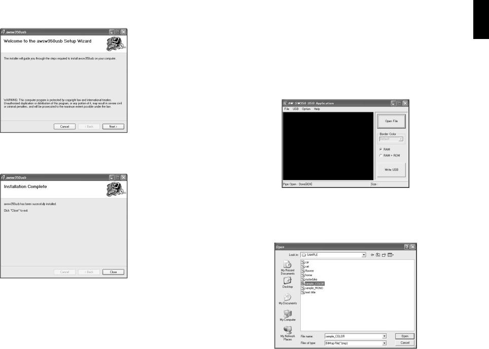
5 The installer programme shown in Fig.7 now starts. Proceed with the installation by following the installer instructions.
Fig.7 Application programme installer start screen
6 This completes the installation of the application programme.
Fig.8 Application programme installation completion screen
■OPERATION METHOD
This section describes how to operate the application programme used with the USB image transfer programme for the AW-SW350.
1 Connect the host computer to the AW-SW350. (Check that the AW-SW350's power is on.)
2 The main screen shown in Fig.9 appears when the application programme used with the USB image transfer programme for the AW-SW350 is started up.
Fig.9 Application programme main screen
3 When the “Open File” button is clicked, the file selection dialogue box shown in Fig.10 appears. Select the image file (BMP, JPG or JPEG) to be transferred, and click “OK”.
Fig.10 File selection dialogue box
ENGLISH
26 (E) |
27 (E) |
4 When the target image appears in the image display area, specify the start or cutout position of the image. Which position is to be specified is determined by the number of pixels in the image file.
•No. of pixels that can be displayed: 720 (H) x 487 (V)
•When the file is smaller than the number of pixels that can be displayed:
The spaces around the image are displayed in black. Move the image to the position where it is to be displayed.
•When the file is larger than the number of pixels that can be displayed:
The frame outlining what can be displayed appears. Move the frame to the position where the image to be displayed is framed.
<When the image is smaller than the number of pixels that can be displayed>
Drag the image displayed in the screen display area and drop it to change its position. (Fig.11)
specify the start position of the image
AW-SW350 programme output
Fig.11 Specifying the image start position
<When the image is larger than the number of pixels that can be displayed>
Drag the frame displayed in the screen display area and drop it to change the cutout position. (Fig.12)
specify the cutout position of the image
AW-SW350 programme output
Fig.12 Specifying the image cutout position
ENGLISH
28 (E) |
29 (E) |

5 Click the “RAM” radio button or “RAM+ROM” radio button to select the type of memory in which the data will be saved. (Fig.13) If “RAM” is selected, the image data is saved only in the frame memory and so it cannot be used after the AW-SW350 power has been turned off and back on again. If “RAM+ROM” is selected, the image data is saved in the flash memory and so it can be used after the AW-SW350 power has been turned off and back on again. However, the actual transfer takes longer than when “RAM” is selected.
|
Status after power has been turned off and back on again |
Transfer time |
|
|
|
RAM |
Transferred image data cannot be used |
Approx. 10 sec. |
|
|
|
RAM+ROM |
Transferred image data can be used |
Approx. 60 sec. |
|
|
|
The transfer times given in the above table are approximations only. The actual time taken will depend on the performance of the host computer.
Fig.13 Memory selection
6 Click the “Write USB” button to start transferring the image data. After the completion of the transfer, monitor the AW-SW350's PGM output and check that the image data has been transferred. (Fig.14)
AW-SW350 programme output
Click the
button
Fig.14 PGM check
— When images could not be transferred —
If an error resulted or images could not be transferred because a cable was connected or disconnected, turn off the switcher's power and exit the application programme. Then turn the switcher's power back on again and start up the application again.
ENGLISH
30 (E) |
31 (E) |

CONNECTIONS
●For installation and connection, be sure to ask the store where you purchased the product. ●Before making any connection, switch off all the components of the system.
●Carefully read the manuals for the individual devices connected to the Live Switcher. ●Use coaxial cable to connect video and genlock signals.
■CONNECTION WITHOUT EXTERNAL SYNCHRONIZATION
(Frame Synchronizer ON)
Caution
When unstable video signals, such as those from a VTR, are being used for the input signals, the internal frame synchronizer may not operate correctly.
■CONNECTION FOR EXTERNAL SYNCHRONIZATION
(Frame Synchronizer OFF)
●Adjust the horizontal and colour phases of the cameras. (Read the manual for the camera.)
Camera
|
VIDEO OUT |
Convertible Camera AW —E600 |
G/L IN |
Convertible Camera AW —E600 |
|
Camera |
|
VIDEO OUT |
|
VIDEO OUT |
Convertible Camera AW —E600 |
G/L IN |
Colour monitors |
|
|
||
Convertible Camera AW —E600 |
|
|
PVW OUT PGM OUT |
|
Camera or character |
|
|
Convertible Camera AW —E600 |
generator for key |
|
|
|
synthesis |
|
|
|
|
|
|
|
VIDEO OUT |
|
|
|
|
|
|
|
|
|
|
|
|
|
|
|
|
|
Convertible Camera AW —E600 |
G/L IN |
|
|
|
|
|
|
|
|
|
|
|
|
|
|
VIDEO OUT |
|
|
|
|
BBOUT |
GLIN |
|
|
|
PVW |
|
PGM OUT |
|
|
VIDEO |
|
|
|
|
|
|
|
|
|
|
|
2 |
|
|
|
|
|
||||
|
|
|
|
OUTPUT |
|
|
/BBOUT |
|
|
|
OUT |
1 |
5 |
4 |
3 |
2 |
1 |
|
|
Colour monitors |
|
|
|
|
|
|
|
|
|
|
|
|
|
|
|
IN |
|
Convertible Camera AW —E600 |
|
|
|
|
|
|
|
|
|
|
|
|
|
|
|
|
|
|
|
|
|
|
|
|
|
|
|
|
|
|
|
|
|
|
|
75Ω |
|
|
PVW OUT PGM OUT |
|
|
|
|
|
|
TALLY & INCOM |
|
|
|
|
|
|
||||
|
|
|
|
|
5 |
4 |
|
|
|
3 |
|
2 |
1 |
|
|
|
AUTO |
|
|
|
|
|
|
|
|
|
|
|
|
|
|
||||||
|
|
INPUT |
|
|
|
|
|
|
|
|
|
|
||||||
|
|
|
|
|
|
|
|
|
|
|
|
|
|
|
|
OUT |
||
|
|
|
|
|
|
|
|
|
|
|
|
|
|
PGM |
|
Y / C IN |
|
|
|
|
INPUT |
OUTPUT A |
OUTPUT B |
|
|
DC 12V IN |
|
|
|
|
|
EXT |
Y / C |
|
|
|
|
|
|
A |
1 |
1 |
|
|
SET UP |
USB |
|
TAKE |
OUT |
|
|
|
|
|||
Camera or character |
|
|
|
|
|
|
1 |
2 |
3 |
4 |
|
|
|
|
|
|
|
|
|
THR SEP |
2 |
2 |
AC adaptor |
|
|
|
|
|
|
|
|
|
|
|
|
|
|
generator for key |
|
75Ω HI-Z |
|
|
GND |
|
|
|
|
|
|
|
5 |
4 |
3 |
2 |
1 |
|
|
B |
3 |
3 |
AW-PS505 |
|
|
|
|
|
|
|
|
|
|
|
|
|
|
synthesis |
|
|
|
|
|
|
|
|
|
|
|
|
|
|
||||
VIDEO OUT |
|
|
|
|
|
|
|
|
|
|
|
|
|
|
|
AW-SW350 |
||
|
|
|
|
|
|
|
|
|
|
|
|
|
|
|
|
|||
|
|
|
|
|
|
|
|
|
|
|
|
|
Video distributor |
|
|
Convertible Camera AW —E600 |
|
|
|
|
|
|
|
|
|
|
|
|
WJ-300C |
VTR, etc. |
QFS switch [OFF] |
|
|
|
|
|
|
|
|
|
|
|
|
|
|
WGLIN/BBOUT switch [BBOUT] |
|
|
|
BBOUT |
GLIN |
|
|
|
PVW |
PGM OUT |
|
|
VIDEO |
|
|
|
|
|
|
|
/BBOUT |
|
|
|
OUT |
2 1 |
5 |
4 |
3 |
2 |
1 |
|
|
|
|
|
|
|
|
|
|
|
|
|
|
|
IN |
|
|
Signal |
|
|
|
TALLY & INCOM |
|
|
|
|
|
AUTO |
|
|
|||
|
|
|
|
|
|
|
|
|
75Ω |
|
|
||||
generator |
|
5 |
4 |
|
|
|
3 |
2 |
1 |
|
|
|
|
|
|
|
|
|
|
|
|
|
|
|
|
|
|
OUT |
|
|
|
|
|
|
|
|
|
|
|
|
|
|
|
|
|
|
|
When a signal |
|
|
DC 12V IN |
|
|
|
|
EXT |
PGM |
|
Y / C IN |
|
|
|
|
generator is used to |
|
|
|
|
|
USB |
Y / C |
|
|
|
|
|
|
||
|
|
SET UP |
TAKE |
OUT |
|
|
|
|
|
|
|||||
generate the |
|
|
1 |
2 |
3 |
4 |
|
|
|
|
|
|
|
|
|
AC adaptor |
|
|
|
|
|
|
|
|
|
|
|
|
|
|
|
reference signals for |
GND |
|
|
|
|
|
|
5 |
4 |
3 |
2 |
1 |
|
|
|
the system |
AW-PS505 |
|
|
|
|
|
|
|
|
|
|
|
|
|
|
|
|
|
|
|
|
|
|
|
|
|
AW-SW350 |
|
|
||
|
|
|
|
|
|
|
|
|
|
|
|
|
|
||
|
VTR, etc. |
|
QFS switch [ON] |
|
|
|
|
|
|
||||||
|
|
|
WGLIN/BBOUT switch [GLIN] |
|
|
|
|||||||||
ENGLISH
32 (E) |
33 (E) |

■CONNECTION TO PERSONAL COMPUTER
Camera
VIDEO OUT
Convertible Camera AW —E600
Convertible Camera AW —E600
VIDEO OUT
Convertible Camera AW —E600 |
Colour monitors |
OUT
Camera or character generator for key synthesis
VIDEO OUT |
|
|
|
|
|
|
|
|
|
|
|
|
Convertible Camera AW —E600 |
|
|
|
|
|
|
|
|
|
|
|
|
|
BBOUT |
GLIN |
|
|
|
PVW |
PGM OUT |
|
|
VIDEO |
|
|
|
|
|
|
|
|
|
|
|
||||
|
|
/BBOUT |
|
|
|
OUT |
2 1 |
5 |
4 |
3 |
2 |
1 |
|
|
|
|
|
|
|
|
|
|
|
|
IN |
|
|
|
TALLY & INCOM |
|
|
|
|
|
75Ω |
|||
|
5 |
4 |
|
|
|
3 |
2 |
1 |
|
|
|
AUTO |
|
|
|
|
|
|
|
|
|||||
|
|
|
|
|
|
|
|
|
|
|
|
OUT |
|
|
|
|
|
|
|
|
PGM |
|
Y / C IN |
|
|
|
|
DC 12V IN |
|
|
|
USB |
EXT |
Y / C |
|
|
|
|
|
|
SET UP |
TAKE |
OUT |
|
|
|
|
||||
|
|
1 |
2 |
3 |
4 |
|
|
|
|
|
|
|
AC adaptor |
GND |
|
|
|
|
|
|
5 |
4 |
3 |
2 |
1 |
|
|
|
|
|
|
|
|
|
|
|
||
AW-PS505 |
|
|
|
|
|
|
|
|
|
|
AW-SW350 |
|
|
|
|
|
|
|
|
|
|
|
|
||
VTR, etc. |
|
These switches operate whether the FS |
||||||||||
|
|
|||||||||||
|
|
switch is in the ON or OFF position. |
|
|||||||||
ENGLISH
Windows PC
Connected with
USB cable
34 (E) |
35 (E) |
■EXAMPLE FOR THE CONNECTION WITH PAN/TILT HEADS
AND CONTROL PANEL
●The cameras can be locally controlled by using the pan/tilt head AW-PH300A, multi-hybrid control panel AW-RP505, and multi-port hub AW-HB505.
Pan/tilt head cameras 1 to 4
Convertible Camera AW —E600
Convertible Camera AW —E600
|
|
Colour monitors |
|
|
|||||
Convertible Camera AW —E600 |
|
|
|
|
|
|
|
|
|
|
|
PVW OUT PGM OUT |
|||||||
Camera or character |
|
|
|
|
|
|
|
|
|
generator for key |
|
|
|
|
|
|
|
|
|
synthesis |
VIDEO OUT |
|
|
|
|
|
|
|
|
|
|
|
|
|
|
|
|
|
|
Convertible Camera AW —E600 |
G/L IN |
|
|
|
|
|
|
|
|
|
|
BBOUT |
GLIN |
|
|
|
PVW |
PGM OUT |
|
|
|
|
/BBOUT |
|
|
|
OUT 2 |
1 |
5 |
|
|
|
|
TALLY & INCOM |
|
|
|||
|
|
5 |
4 |
|
|
|
3 |
2 |
1 |
|
|
|
DC 12V IN |
|
|
|
|
EXT |
PGM |
|
|
|
|
|
|
USB |
Y / C |
||
|
|
|
SET UP |
TAKE |
OUT |
||||
|
|
|
1 |
2 |
3 |
4 |
|
|
|
|
AC adaptor |
GND |
|
|
|
|
|
|
5 |
AW-PS505
VIDEO IN 1-4
VIDEO
4 |
3 |
2 |
1 |
|
|
|
IN |
|
|
|
75Ω |
|
|
|
AUTO |
|
|
|
OUT |
|
Y / C IN |
|
|
4 |
3 |
2 |
1 |
AW-SW350
VTR, etc.
To pan/tilt head AW-PH300A,
Camera AW-E300/E600/E800A
|
|
|
|
Multi-port hub |
||
|
|
|
|
AW-HB505 |
||
|
|
T O C A M E R A PA M / T I LT H E A D |
|
|
T O C O N T R O L PA N E L |
|
|
|
|
|
|
PREVIEW OUT |
|
VIDEO |
VIDEO |
VIDEO |
VIDEO |
VIDEO |
|
|
IN |
IN |
IN |
IN |
IN |
|
|
PAM/TILT |
PAM/TILT |
PAM/TILT |
PAM/TILT |
PAM/TILT |
PAM/TILT |
|
CONTROL OUT |
CONTROL OUT |
CONTROL OUT |
CONTROL OUT |
CONTROL OUT |
CONTROL IN |
|
G/L S-VIDEO OUT |
G/L S-VIDEO OUT |
G/L S-VIDEO OUT |
G/L S-VIDEO OUT |
G/L S-VIDEO OUT |
G/L |
|
OUT |
OUT |
OUT |
OUT |
OUT |
IN |
|
VIDEO OUT |
VIDEO OUT |
VIDEO OUT |
VIDEO OUT |
VIDEO OUT |
|
|
CAMERA |
CAMERA |
CAMERA |
CAMERA |
C A M E R A |
CAMERA |
|
CONTROL OUT |
CONTROL OUT |
CONTROL OUT |
CONTROL OUT |
CONTROL OUT |
CONTROL IN |
|
5 |
4 |
3 |
2 |
1 |
D C 1 2 V I N |
|
S E E M A N U A L |
||||||
|
|
|
|
|
||
VIDEO OUT 1-4 |
Preview monitor |
AC adaptor |
||||
|
|
|||||
AW-PS505
G/L OUT
G/L IN |
G / L |
I N |
PREVIEW MONITOR OUT |
|
|
|
D C 1 |
2 V |
I N |
|
|
|
|
|
|
|
|
|
|
|
|
T D |
M U L T I P O R T H U B |
AUX CONTROL IN |
|
|
|
|
|
|
|
|
|
|
|
T A L L Y |
|
||
|
P A N / T I L T |
C A M E R A |
|
4 |
3 |
2 |
|
1 |
|
|
C O N T R O L O U T C O N T R O L O U T G / L O U T P R E V I E W I N |
5 |
|
||||||
Multi-hybrid control panel
AW-RP505
AC adaptor
AW-PS301
The FS switch may be in either the ON or OFF position.
If high picture quality is desired, set the FS switch to OFF and adjust each camera for horizontal and colour phases.
(Refer to the instruction manual for the camera.)
ENGLISH
36 (E) |
37 (E) |
RACK MOUNTING
■RACK MOUNTING
●Do not mount the Live Switcher on a closed rack or bookshelf. (Otherwise, heat will build up inside and may cause a fire.)
●Keep the ventilation port open to secure good flow of air.
|
POWER |
|
|
WIPE |
PATTERN |
INCOM |
|
GEN- |
LEVEL |
TRANS |
|
LOCK |
|
|
|
|
PHASE |
ITION |
TIME |
|
|
2 |
|
Rack mounting parts |
1 |
|
|
|
A |
|
|
3 |
|
|
4 |
|
|
B |
|
|
|
B |
Connecting
plate Mounting screw
Mounting screw
Holes for connecting plate (Bottom)
INFORMATION RELATED TO SYSTEM UPGRADES |
|
ENGLISH |
||
(1) Switcher phases |
|
|
||
|
|
|
||
1) Video signal output phase (frame synchronizer is OFF) |
|
|
|
|
|
|
|
||
Video signal input phase |
|
|
|
|
Video signal output phase |
|
Approx. 50nS |
||
|
||||
BBphase
2)Video signal input phase (frame synchronizer is ON)
Input phase range
max. of 1 frame
BB phase
3) Genlock adjustment range
|
|
Approx. |
Approx. 3µS |
|
1µS |
|
|
|
BB phase
(2) TALLY & INCOM connectors
Use a Mini DIN type 6-pin connector for tally and intercom connections. (e.g.) TCP8060-01-520 manufactured by Hosiden Corporation
38 (E) |
39 (E) |

SPECIFICATIONS/STANDARD ACCESSORIES
■SPECIFICATIONS
|
|
|
|
|
|
|
|
|
Power supply: |
|
12 V DC (+10.8 ~ 16.0V) |
|
|||
|
Power consumption: |
|
16 W |
|
|
||
|
|
|
|
|
|
||
|
|
|
|
|
|
|
|
|
|
|
indicates safety information. |
|
|
||
|
|
|
|
|
|||
|
|
|
|
|
|
|
|
Video Inputs |
|
|
|
|
|||
|
Composite video signal: |
VBS: 1.0 V[p-p]/75 Ω!5 (BNC connector, automatic |
|||||
|
|
|
|
|
termination) |
||
|
Y/C: |
Y: |
1.0 V[p-p]/75 Ω |
||||
|
|
|
|
C: 0.3 V[p-p]/75 Ω!5 (S connector) |
|||
Video Outputs |
|
|
|
|
|||
|
Composite video output: |
VBS: 1.0 V[p-p]/75 Ω!2 (BNC connector) |
|||||
|
Y/C: |
Y: |
1.0 V[p-p]/75 Ω!1 |
||||
|
|
|
|
C: 0.3 V[p-p]/75 Ω!1 (S connector) |
|||
|
Preview output: |
VBS: 1.0 V[p-p]/75 Ω!1 (BNC connector) |
|||||
|
Black burst signal: |
BBS: Sync: 0.3 V[p-p], C: 0.3 V[p-p] burst level/ |
|||||
|
|
|
|
|
75 Ω!1 (BNC connector) |
||
|
Signal loopthrough output: |
1 each (BNC connector) |
|||||
Functions and Performance |
|
|
|
|
|||
|
Frame synchronizer: |
10 bit quantization, 13.5MHz sampling |
|||||
|
|
|
|
Mounted to each channel of VIDEO IN 1 to 5. |
|||
|
Wipe patterns: |
9 patterns |
|
|
|||
|
Wipe directions: |
3 directions (normal, reverse, normal/reverse) |
|||||
|
Mix: |
Cross fader |
|||||
|
Auto take: |
Wipe, Mix (time adjustable) |
|||||
|
Key synthesis: |
Self Key, Linear Key |
|||||
|
Intercom: |
1 to 5 (6-pin connector, 3/4 wire selectable), |
|||||
|
|
|
|
Intercom jack (M6 jack) |
|||
|
Tally control: |
1 to 5 (open collector output) |
|||||
|
Colour bar: |
Internal (EBU, Black/Colour selectable) |
|||||
|
White and black signals: |
Internal |
|
|
|||
|
Frequency response: |
FS ON: |
6.0MHz +1 dB, –3dB |
||||
|
|
|
|
FS OFF: |
10.0MHz +1 dB, –3dB |
||
|
S/N: |
FS ON: |
More than 58 dB |
||||
|
|
|
|
FS OFF: |
More than 65 dB |
||
|
DG/DP: |
FS ON: |
±2°, ±2% |
|
|||
|
|
|
|
FS OFF: |
±1.5°, ±1.5% |
|
|
Operating temperature range: |
0˚C to 40˚C |
ENGLISH |
|
Humidity: |
30% to 90% |
||
|
|||
Dimensions (W!H!D): |
210!86!176 mm |
|
|
Weight: |
Approx. 2.2 kg |
|
|
Finish: |
AV ivory painting (Munsell 7.9Y6.8/0.8 or close to it) |
|
Weight and dimensions indicated are approximate.
Specifications are subject to change without notice.
■STANDARD ACCESSORIES
Tally/intercom connector ............................................................................................. |
5 pcs. |
Rack mounting parts ................................................................................................... |
2 pcs. |
Connecting plate ........................................................................................................... |
1 pc. |
Mounting screws ........................................................................................................... |
1 set |
Image transfer programme setup CD ............................................................................ |
1 pc. |
40 (E) |
41 (E) |

$ Öffnen Sie nicht das Gerät durch Abschrauben von Gehäuseteilen.
Zur Vermeidung von elektrischem Schlag darf das Gehäuse nicht geöffnet werden. Im Geräteinneren befinden sich keine Teile, die vom Benutzer gewartet werden können.
Wartungsund Reparaturarbeiten grundsätzlich autorisiertem Kundendienstpersonal überlassen.
WARNUNG:
UM BRANDODER STROMSCHLAGGEFAHR ZU REDUZIEREN, MUSS DIESES GERÄT VON ALLEN FLÜSSIGKEITEN FERNGEHALTEN WERDEN. VERMEIDEN SIE GEBRAUCH UND LAGERUNG DES GERÄTES AN ORTEN, AN DENEN DIE GEFAHR BESTEHT, DASS ES MIT FLÜSSIGKEITEN BETROPFT ODER BESPRITZT WIRD, UND STELLEN SIE KEINE FLÜSSIGKEITSBEHÄLTER AUF DAS GERÄT.
VORSICHT:
Nur das empfohlene Zubehör verwenden, um die Gefahr von Feuer und elektrischem Schlag sowie Störungen auszuschalten.
VORSICHT:
UM DIE GEFAHR VON FEUER UND ELEKTRISCHEM SCHLAG AUSZUSCHALTEN, SIND ÄNDERUNGEN VON SCHALTEREINSTELLUNGEN IM GERÄTEINNEREN AUSSCHLIESSLICH AUTORISIERTEM KUNDENDIENST-PERSONAL ZU ÜBERLASSEN.
Hinweis:
Das Typenschild (Seriennummernschild) befindet sich an der Unterseite des Geräts.
ist die Sicherheitsinformation.
Die Informationsmarkierung dieses Produkts befindet sich an der Unterseite des Geräts. Die Seriennummer dieses Produkts befindet sich an der Unterseite des Geräts.
Bitte tragen Sie die Seriennummer dieses Geräts als Kaufnachweis in das dafür vorgesehene Feld ein, um die Identifizierung im Falle eines Diebstahls zu erleichtern.
Modell-Nr.
Serien-Nr.
INHALT
WARNUND VORSICHTSHINWEISE ZUR SICHERHEIT .................................................................... |
4 |
|
|
DEUTSCH |
|||
MERKMALE .......................................................................................................................................... |
6 |
||
VORWORT ............................................................................................................................................ |
5 |
|
|
VORSICHTSMASSNAHMEN |
7 |
|
|
|
|||
WICHTIGE BEDIENUNGSELEMENTE UND IHRE FUNKTIONEN ...................................................... |
8 |
|
|
■OBERSEITE (STEUERPULT) ................................................................................................ |
8 |
|
|
■RÜCKWAND ......................................................................................................................... |
15 |
|
|
BILDÜBERTRAGUNGSFUNKTION ................................................................................................... |
20 |
|
|
■FUNKTIONEN ....................................................................................................................... |
20 |
|
|
■TECHNISCHE DATEN ......................................................................................................... |
21 |
|
|
■INSTALLIEREN DES GERÄTETREIBERS .......................................................................... |
22 |
|
|
■INSTALLIEREN DES ANWENDUNGSPROGRAMMS ......................................................... |
25 |
|
|
■BEDIENUNGSVERFAHREN ................................................................................................ |
27 |
|
|
ANSCHLÜSSE .................................................................................................................................... |
32 |
|
|
■ANSCHLUSS OHNE EXTERNE SYNCHRONISIERUNG .................................................... |
32 |
|
|
■ANSCHLUSS FÜR EXTERNE SYNCHRONISIERUNG ....................................................... |
33 |
|
|
■ANSCHLUSS AN EINEN PC ................................................................................................ |
34 |
|
|
■ANSCHLUSSBEISPIEL MIT SCHWENK- |
|
|
|
/NEIGEKÖPFEN UND STEUERPULT ................................... |
36 |
|
|
EINBAU IN EIN RACK ........................................................................................................................ |
38 |
|
|
■EINBAU IN EIN RACK .......................................................................................................... |
38 |
|
|
INFORMATIONEN ZU SYSTEM-UPGRADES ................................................................... |
39 |
|
|
TECHNISCHE DATEN/STANDARDZUBEHÖR ................................................................................. |
40 |
|
|
■TECHNISCHE DATEN ......................................................................................................... |
40 |
|
|
■STANDARDZUBEHÖR ......................................................................................................... |
41 |
|
2 (G) |
3 (G) |

WARNUND VORSICHTSHINWEISE ZUR SICHERHEIT
 WARNUNG
•Alle Wartungsarbeiten qualifiziertem Personal überlassen
Um die Gefahr von elektrischen Schlägen zu reduzieren, sollte die Deckplatte oder die Rückwand nur von qualifiziertem Personal entfernt werden. Überlassen Sie alle Montage-, Anschlussund Wartungsarbeiten qualifiziertem Personal.
•Eindringen von Wasser oder Feuchtigkeit verhüten
Achten Sie darauf, dass weder Wasser noch Feuchtigkeit in das Produkt eindringt, und dass es keiner Feuchtigkeit ausgesetzt wird, um Brand und elektrischen Schlag zu verhüten.
•Falls das Produkt Rauch oder einen Geruch abgibt, falls Wasser oder ein Fremdkörper in das Innere eindringt, falls es durch Fallenlassen beschädigt wird, oder falls ein Fehler festgestellt wird, stellen Sie sofort den Betrieb ein.
•Unterlassen Sie das Zerlegen oder Modifizieren des Produkts, um einen Brand oder elektrischen Schlag zu verhüten.
 VORSICHT
•Lassen Sie das Produkt nicht fallen, setzen Sie es keinen starken Erschütterungen aus, und stellen Sie sich auch nicht darauf, um einen Brand und Verletzungen zu verhüten.
•Installieren Sie das Produkt nicht an einem Ort, der Feuchtigkeit und Staub ausgesetzt ist, weil es sonst zu einem Brand oder elektrischen Schlag kommen kann.
•Installieren Sie den Live Switcher nicht in einem geschlossenen Rack oder Regal. (Anderenfalls kommt es zu einem internen Wärmestau, der einen Brand verursachen kann.)
•Halten Sie die Ventilationsöffnung frei, um gute Luftzirkulation zu gewährleisten.
VORWORT
Der AW-SW350 besitzt trotz seiner kompakten Abmessungen fünf Videoeingänge sowie Wipe-, Mixund Key-Synthesefunktionen. Da er einen eingebauten Frame Synchronizer besitzt, akzeptiert er die Eingabe von asynchronen Signalen. Darüber hinaus ermöglicht er die Konfiguration von Systemen mit Hilfe der von ihm ausgegebenen Black-Burst-Signale, und er unterstützt auch externe Synchronisierung (oder Genlock) durch externe Synchronsignale. Seine Bildübertragungsfunktion ermöglicht es, die mit Hilfe eines Personal Computers erzeugten Bilder und Texte über den USB-Anschluss im Bildmischpult aufzunehmen. Das Bildmischpult kann am Aufnahmeort verwendet werden, weil es mit externer Stromversorgung (12 V DC) arbeitet, während seine Rotlichtausgänge und Intercom-Ein-/Ausgänge eine einfache Systemkonfiguration gestatten.
DEUTSCH
4 (G) |
5 (G) |

MERKMALE
•Fünf Eingänge trotz kompakter Abmessungen
Das Bildmischpult verfügt über fünf FBAS-Signaleingänge. (Automatische Terminierung. Durchschleifausgang vorhanden.) Da das Gerät eine S-Buchse (4-polig) besitzt, kann es auch YC-Signale verarbeiten. Mit Hilfe eines Schalters ist eine Umschaltung zwischen Eingang 5 und dem internen Vollbildspeicher möglich. Das interne Schwarzoder Farbsignal (9 Muster) kann gewählt werden.
•Drei Programmund Vorschauausgänge vorhanden
Effektausgänge mit zwei FBAS-Videoausgängen (BNC-Buchsen) und einem YC-Signalausgang (S-Buchse, 4-polig) sind vorhanden, so dass sich ein System mit Monitoren, Videorecordern usw. leicht aufbauen lässt. Der AW-SW350 besitzt auch einen Vorschauausgang, um die nächste Operation zu überprüfen. (Look Ahead-Vorschau)
•Frame Synchronizer-System und Genlock-System werden unterstützt
Das Bildmischpult enthält einen Hochleistungs-10-Bit-Frame-Synchronizer: Das bedeutet, dass asynchrone Signale direkt in die angeschlossene Kamera oder ein anderes entsprechendes Gerät eingegeben werden können, ohne den Genlock zu aktivieren. Seine Eingänge sind mit einer Frame Synchronizer-Funktion ausgestattet, so dass seine Bilder nicht einfrieren, selbst wenn die Vollbilder umgeschaltet werden. Wahlweise kann der Frame Synchronizer auch abgeschaltet werden, der Genlock kann auf eine Kamera oder ein anderes entsprechendes Gerät angewandt werden, und das Gerät kann auch als Breitbandmischer mit minimaler Verschlechterung der Bildqualität (Auflösung von 800 Linien) eingesetzt werden.
•Genlock
Das Bildmischpult ermöglicht Taktsynchronisierung auf das Referenz-Synchronsignal eines externen Geräts. Durch Benutzung des BB-Ausgangs kann außerdem das System unter Verwendung der Synchronisierung des Bildmischpults als Referenz aktualisiert werden.
•Bildübertragung, Soft Keys und Linear Keys
Da das Bildmischpult AW-SW350 einen internen Vollbild-Speicher besitzt, können mit einem PC erzeugte Bilder über den USB-Anschluss in diesen Speicher aufgenommen werden. Es sind neun verschiedene Muster für Wipe vorhanden, und drei Weichheitsstufen stehen zur Auswahl. Mit Hilfe von Linear Key-Operationen kann Text ebenfalls reibungslos synthetisiert werden.
•Externe Stromversorgung
Das Bildmischpult kann sowohl drinnen als auch draußen verwendet werden, da es mit einer externen Stromversorgung von 12 V DC arbeitet.
(Es ist jedoch nicht regendicht oder tropfwassergeschützt. Setzen Sie das Bildmischpult weder Regen noch Feuchtigkeit aus.)
•Rotlichtund Intercom-Ausgänge vorhanden
Je fünf Rotlichtausgänge und Intercom-Ein- und -Ausgänge sind vorhanden, so dass das Bildmischpult direkt mit herkömmlichen Systemen eingesetzt werden kann. (Das Bildmischpult besitzt seine eigene Intercom auf dem Pult.)
VORSICHTSMASSNAHMEN
• Sorgfältig behandeln. |
|
|
Lassen Sie das Bildmischpult nicht fallen, und setzen Sie es auch keinen starken Erschütterungen |
|
|
oder Vibrationen aus. Dies ist wichtig, um Störungen und Unfälle zu verhüten. |
|
|
DEUTSCH |
||
• Betriebstemperaturbereich von 0 bis 40 °C |
||
|
||
Vermeiden Sie den Gebrauch an kalten oder heißen Orten (unter 0 °C bzw. über 40 °C), weil tiefe |
|
|
oder hohe Temperaturen sich negativ auf die Innenteile auswirken. |
|
|
|
|
• Vor dem Anschließen oder Abtrennen von Kabeln den Strom ausschalten.
Schalten Sie unbedingt die Stromversorgung aus, bevor Sie die Kabel anschließen oder abtrennen.
• Feuchte und staubige Orte vermeiden.
Vermeiden Sie den Gebrauch des Bildmischpults an feuchten und staubigen Orten, weil sonst die Innenteile beschädigt werden können.
• Pflege
Wischen Sie das Bildmischpult mit einem trockenen Tuch ab, nachdem Sie es ausgeschaltet haben. Um hartnäckigen Schmutz zu entfernen, feuchten Sie ein Tuch mit verdünnter Haushaltsreinigerlösung an, wringen Sie es gut aus, und wischen Sie das Gerät vorsichtig ab.
Hinweis
•Verwenden Sie keine leichtflüchtigen Lösungsmittel, wie Benzin oder Lackverdünner.
•Wenn Sie ein chemisch behandeltes Reinigungstuch verwenden, lesen Sie vor Gebrauch die Vorsichtshinweise sorgfältig durch.
6 (G) |
7 (G) |
WICHTIGE BEDIENUNGSELEMENTE UND IHRE FUNKTIONEN
■OBERSEITE (STEUERPULT)
|
|
|
|
|
Live Switcher AW-SW350 |
|
POWER |
|
WIPE PATTERN |
|
TRANSITION TIME |
|
|
ON |
|
|
|
|
|
|
|
WH1 |
WH2 |
WH3 |
AUTO TAKE |
KEY AUTO |
A |
OFF |
|
|
||||
S F 0 |
S F 1 |
S F 2 |
|
|
|
|
|
|
|
|
|||
|
YLW |
CYN |
GRN |
KEY |
|
|
INCOM MWR |
I N T |
F R Z |
|
|
||
|
|
|
||||
GAIN CLIP
|
|
MGT |
RED |
BLE |
|
|
|
|
LEVEL |
|
I N V |
|
|
|
|
GEN-LOCK PHASE |
|
|
SOURCE |
KEY AUTO |
|
||
SETTING |
COLOR |
IN5 |
|
|
|||
H |
SC |
SC FINE |
|
|
|
||
|
N |
|
|
|
|||
|
|
|
|
|
|
|
|
|
|
|
|
N / R |
FMEM |
|
|
|
|
|
|
R |
|
|
|
|
|
|
|
|
|
|
|
|
|
|
A |
FRZ |
MIX |
|
|
|
|
|
|
|
|||
|
|
|
|
|
|
|
|
|
|
|
|
|
WIPE |
|
|
1 |
2 |
3 |
4 |
5 |
BLACK |
|
|
FMEM |
COLOR |
|
|
||||
|
|
|
|
BAR |
|
|
|
|
|
|
|
|
AUTO |
TAKE |
B |
|
|
|
|
|
|
|
|
|
|
|
B |
|
|
|
|
QBetriebslampe [POWER]
Leuchtet auf (grün), wenn Strom der Gleichstrom-Eingangsbuchse L zugeführt und der Ein-Aus- Schalter W auf ON gestellt wird, und erlischt, wenn der Ein-Aus-Schalter W auf OFF gestellt wird.
WEin-Aus-Schalter [POWER ON/OFF]
Wird dieser Schalter auf ON gestellt, wird das Gerät eingeschaltet, und die Betriebslampe Q leuchtet auf, vorausgesetzt, dass der Gleichstrom-Eingangsbuchse L Strom zugeführt wird. Wird der Schalter auf OFF gestellt, wird das Gerät ausgeschaltet, und die Betriebslampe Q erlischt.
Vorsicht
Selbst in der Stellung OFF des Ein-Aus-Schalters arbeiten einige der Stromversorgungsschaltungen noch. Um die Stromversorgung vollständig auszuschalten, muss das externe Netzgerät ausgeschaltet werden.
EWipe-Muster-Wahltasten [WIPE PATTERN]
Diese Tasten dienen zur Wahl eines Wipe-Musters, nachdem die Taste WIPE y gedrückt wurde. Neun Muster stehen zur Auswahl. Die gewählte Taste leuchtet auf.
DEUTSCH
RUmschalttaste [SETTING]
Diese Taste fungiert als Umschalttaste für die Wipe-Muster. Während sie gedrückt gehalten wird, können die unten beschriebenen Funktionen mit den Wipe-Muster-Wahltasten gewählt werden. Die Funktionen werden in blauer Schrift angezeigt.
SF0 |
|
|
SF1 |
|
|
|
SF2 |
|
|
|
|
|
|
|
|
||||
|
|
|
|
|
|
|
|
||
MWR |
|
|
INT |
|
|
|
FRZ |
|
|
|
|
|
|
|
|
|
|||
|
|
|
|
|
|
||||
|
|
|
|
|
|
|
|
|
|
|
|
|
|
|
|
|
|
|
|
INV
SF0, SF1, SF2: Diese Tasten werden verwendet, um die drei Wipe-Weichheitsstufen einzustellen. Die minimale Weichheitsstufe erhält man mit SF0 (Hard Key), und die maximale Weichheitsstufe erhält man mit SF2.
MWR: |
Mit dieser Taste kann der Benutzer die Anfangszustände der Tafel einstellen, wenn |
|
die Stromversorgung eingeschaltet wird. |
|
Stellen Sie zuerst die Zustände der Tafel ein, die aufgezeichnet werden sollen. |
|
Nachdem die Einstellung durchgeführt worden ist, drücken Sie MWR bei gedrückt |
|
gehaltener Taste SETTING, bis die neun Tasten ausgeschaltet werden. Die |
|
aufgezeichneten Zustände werden beim nächsten Einschalten der |
|
Stromversorgung wiederhergestellt. |
INT: |
Diese Taste dient zur Wiederherstellung der werksseitigen Anfangseinstellungen. |
|
Drücken Sie INT, während Sie die Taste SETTING gedrückt halten, bis die neun |
|
Tasten ausgeschaltet werden. Beim nächsten Einschalten des Geräts werden dann |
|
die Werkseinstellungszustände wiederhergestellt. |
FRZ: |
Diese Taste wird verwendet, um das Einfrieren des Signals von Videoeingang 5 auf |
|
ON oder OFF zu setzen. Wird FRZ bei gedrückt gehaltener Taste SETTING |
|
gedrückt, wird das Signal von Videoeingang 5 eingefroren. Während das Signal |
|
eingefroren ist, leuchtet die LED FRZ w auf. Dieses Signal kann als Quelle des |
|
Signals VIDEO IN 5 verwendet werden. |
|
Wenn die Einfrierfunktion verwendet wird, während sich der Schalter FS in der |
|
Stellung OFF befindet, wird nur das Signal des Videoeingangs 5 auf den Zustand |
|
FS ON gesetzt. |
8 (G) |
9 (G) |
INV: |
Diese Taste wird verwendet, um die Polarität des Key-Signals umzukehren. |
|
Verwenden Sie den Umkehrmodus, wenn die Eingabe aus schwarzem Text auf |
|
weißem Grund besteht. |
|
Wenn die Funktion INV verwendet wird, während VIDEO IN 5 als Key-Quelle |
|
gewählt ist und der Schalter FS auf OFF steht, wird nur das Signal von |
|
Videoeingang 5 in den Zustand FS ON versetzt. |
THintergrundfarben-Wahltaste [COLOR]
Diese Taste fungiert als Umschalttaste für die Wipe-Muster-Wahltasten. Während Sie gedrückt gehalten wird, kann mit den Wipe-Muster-Wahltasten die für den Farbhintergrund zu verwendende Farbe gewählt werden, wie unten gezeigt. Die Funktionen werden in roter Schrift angezeigt.
WH1 |
|
|
WH2 |
|
|
|
WH3 |
|
|
YLW |
|
|
CYN |
|
|
|
GRN |
|
|
|
|
|
|
|
|
|
|||
|
|
|
|
|
|
|
|||
|
|
|
|
|
|
||||
MGT |
|
|
RED |
|
|
|
BLE |
|
|
|
|
|
|
|
|
|
|||
|
|
|
|
|
|
|
|||
|
|
|
|
|
|
|
|||
|
|
|
|
|
|
|
|
|
|
|
|
|
|
|
|
|
|
|
|
WH1: |
Weiß 100% |
WH2: |
Weiß 90% |
WH3: |
Weiß 80% |
YLW: |
Gelb |
CYN: |
Cyan |
GRN: |
Grün |
MGT: |
Magenta |
RED: |
Rot |
BLE: |
Blau |
YWipe-Richtungs-Wahlschalter [N/ N/R/ R]
Dient zur Wahl einer von drei Richtungen, in der die Signale durch Verschieben des Überblendhebels i von A nach B oder umgekehrt auf dem Bildschirm übergeblendet werden.
N (Normal):
Wenn der Überblendhebel i von A nach B geschoben wird, wird das Bild vom gewählten A-Bus- Signal in der Richtung des auf der Wipe-Muster-Wahltaste dargestellten schwarz/weißen Musters zum gewählten B-Bus-Signal übergeblendet. Ebenso, wenn der Überblendhebel i von B nach A geschoben wird, wird das Bild auf dem Bildschirm vom gewählten B-Bus-Signal zum gewählten A-Bus-Signal übergeblendet.
R (Reverse):
Wenn der Überblendhebel i von A nach B geschoben wird, wird das Bild vom gewählten A-Bus- Signal in der Richtung des auf der Wipe-Muster-Wahltaste dargestellten weiß/schwarzen Musters zum gewählten B-Bus-Signal übergeblendet. Ebenso, wenn der Überblendhebel i von B nach A geschoben wird, wird das Bild auf dem Bildschirm vom gewählten B-Bus-Signal zum gewählten A-Bus-Signal übergeblendet.
N/R (Normal/Reverse):
Wenn der Überblendhebel i von A nach B geschoben wird, wird das Bild vom gewählten A-Bus- Signal in der Richtung des auf der Wipe-Muster-Wahltaste dargestellten schwarz/weißen Musters zum gewählten B-Bus-Signal übergeblendet. Wenn der Überblendhebel i von B nach A geschoben wird, wird das Bild auf dem Bildschirm vom gewählten B-Bus-Signal zum gewählten A-Bus-Signal übergeblendet.
[Beispiel] Gewähltes Wipe-Muster
Überblendhebel |
Normal (N) |
Reverse (R) |
Normal/Reverse (N/R) |
|
||||||||||||||||||||||
A |
|
|
|
|
|
|
|
|
|
|
|
|
|
|
|
|
|
|
|
|
|
|
|
|
||
|
|
|
|
|
|
|
|
|
|
|
|
|
|
|
|
|
|
|
|
|
|
|
|
|||
|
|
|
|
|
A |
B |
|
|
B |
|
A |
|
|
A |
|
B |
|
|
||||||||
|
|
|
|
|
|
|
|
|
|
|
|
|
||||||||||||||
|
|
|
|
|
|
|
|
|
|
|
|
|
||||||||||||||
|
|
|
|
|
|
|
|
|
|
|
|
|
|
|
|
|
|
|
|
|
|
|
|
|
|
|
B |
|
|
|
|
|
|
|
|
|
|
|
|
|
|
|
|
|
|
|
|
|
|
|
|
||
A |
|
|
|
|
|
|
|
|
|
|
|
|
|
|
|
|
|
|
|
|
|
|
|
DEUTSCH |
||
|
|
|
|
|
|
|
|
|
|
|
|
|
|
|
|
|
|
|
|
|
|
|
|
|
|
|
|
|
|
|
|
B |
A |
|
|
A |
|
B |
|
|
A |
|
B |
|
|||||||||
|
|
|
|
|
|
|
|
|
|
|
|
|||||||||||||||
|
|
|
|
|
|
|
|
|
|
|
|
|
||||||||||||||
B |
|
|
|
|
|
|
|
|
|
|
|
|
|
|
|
|
|
|
|
|
|
|
|
|
||
|
|
|
|
|
|
|
|
|
|
|
|
|
|
|
|
|
|
|
|
|
|
|
|
|||
UÜbergangszeitregler [TRANSITION TIME] |
|
|
|
|
|
|
|
|
|
|
|
|
|
|
|
|
|
|||||||||
|
|
|
|
|
|
|
|
|
|
|
|
|
|
|
|
|
||||||||||
Diese Regler dienen zur Einstellung der Übergangszeit bei Auto-Fader-Operationen. |
|
|||||||||||||||||||||||||
AUTO TAKE: |
Dieser Regler dient zur Einstellung der Übergangszeit von MIX oder WIPE, wenn |
|
||||||||||||||||||||||||
|
|
|
die Taste AUTO TAKE u gedrückt worden ist. Eine beliebige Übergangszeit von 0 |
|
||||||||||||||||||||||
|
|
|
bis etwa 10 Sekunden kann eingestellt werden. |
|
|
|
|
|
|
|
|
|
||||||||||||||
KEY AUTO: |
Dieser Regler dient zur Einstellung der Übergangszeit, wenn die Taste KEY AUTO |
|
||||||||||||||||||||||||
|
|
|
I gedrückt worden ist. Eine beliebige Übergangszeit von 0 bis etwa 5 Sekunden |
|
||||||||||||||||||||||
|
|
|
kann eingestellt werden. |
|
|
|
|
|
|
|
|
|
|
|
|
|
|
|
|
|
||||||
Durch Drehen der Regler entgegen dem Uhrzeigersinn wird die Übergangszeit verkürzt, während sie durch Drehen im Uhrzeigersinn verlängert wird. Werden die Regler bis zum Anschlag entgegen dem Uhrzeigersinn gedreht, wird die Übergangszeit auf 0 Sekunden eingestellt, woraus eine Schnittoperation resultiert. Selbst wenn externe Takes mit Hilfe externer Schalter durchgeführt werden, bleiben die Einstellungen dieser Regler in Kraft. (Wenn ein Schalter an EXT TAKE H angeschlossen ist)
Vorsicht
Stellen Sie die Übergangszeiten mit diesen Reglern im Voraus ein, bevor Sie mit Auto-Fader- Operationen beginnen.
IKey-Synthese-Regler [KEY]
Diese Regler werden zur Durchführung der auf Key-Synthese bezogenen Einstellungen verwendet. GAIN, CLIP: Das AW-SW350 besitzt ein Linear-Key-System für Key-Synthese, um eine
reibungslose Synthese zu gewährleisten, und diese beiden Regler dienen zum Einstellen der Synthesepegel, wenn Text und andere Daten mit den Key-Signalen synthetisiert werden sollen. Der Regler CLIP dient zur Einstellung des Referenzpegels, bei dem die Key-Signale erzeugt werden sollen, und Signale oberhalb dieses Pegels werden synthetisiert. Falls Rauschen in den Hintergrundbildern vorhanden ist, stellen Sie den CLIP-Pegel höher ein. Der Regler GAIN dient zum Anheben oder Absenken des Pegels der Key-Signale. Stellen Sie den Pegel so ein, dass der Text usw. sauber und klar synthetisiert werden kann.
[Einstellungsbeispiel]
Drehen Sie den Regler CLIP bis zum Anschlag entgegen dem Uhrzeigersinn, und während Sie den Bildschirm beobachten, stellen Sie den Regler GAIN ein, um saubere und klare Bilder zu erhalten. Justieren Sie anschließend die Regler CLIP und GAIN abwechselnd, um den optimalen Zustand zu erzielen.
10 (G) |
11 (G) |

KEY AUTO: |
Mit dieser Taste wird die Key-Synthese auf ON oder OFF gestellt. |
|
Wird die Taste gedrückt, leuchtet sie auf, und Key-Synthese wird für den Text usw. |
|
durchgeführt. Die Übergangszeit für die Key-Synthese wird mit dem Regler KEY |
|
AUTO U eingestellt. Wenn die Taste erneut gedrückt wird, erlischt ihre Lampe, |
|
und die für die Key-Synthese verwendeten Eingangssignale werden unverändert |
|
mit dem Basisbild synthetisiert, aber je nach dem Pegel der Eingangssignale |
|
können eventuell keine sauberen und klaren Bilder erzielt werden. |
SOURCE: |
Mit diesem Schalter wählen Sie, ob das Signal von VIDEO IN 5 oder das Bild im |
|
Vollbildspeicher als Quellmaterial für die Key-Synthese verwendet wird. |
|
Verwenden Sie für die Key-Signale schwarze Basispegelsignale, und stellen Sie |
|
eine Quelle mit weißen Schriftzeichen bereit. |
|
Eine Quelle mit farbigen Schriftzeichen kann auch mit einer schwarzen Basis |
|
synthetisiert werden, aber je nach dem Pegel der Schriftzeichensignale können |
|
eventuell keine sauberen und klaren Bilder erzielt werden. |
|
(Durch Umkehren der Polarität der Key-Signale können auch Bilder mit einem |
|
weißen Basispegel synthetisiert werden. Einzelheiten über die Key-Umkehr finden |
|
Sie unter SETTING R.) |
Hinweis
Gehen Sie folgendermaßen vor, um die Key-Synthese auf dem PVW-Bildschirm immer abgeschaltet zu halten.
1.Drücken Sie die Tasten SETTING R und COLOR T gleichzeitig.
2.Während Sie die zwei Tasten in Schritt 1 gedrückt halten, drücken Sie die Taste KEY AUTO. Die Lampe der Taste KEY AUTO leuchtet nun auf.
Um die Key-Synthese auf dem PVW-Bildschirm wieder einzuschalten, wiederholen Sie den gleichen Vorgang. Die Lampe der Taste KEY AUTO erlischt dann.
OIntercom-Buchse [INCOM]
Schließen Sie eine Intercom-Kopfgarnitur an diese Buchse an. Verwenden Sie die empfohlene Kopfgarnitur (von Ashida Onkyo MT-12MFB-03).
PIntercom-Lautstärkeregler [INCOM LEVEL]
Dient zum Einstellen der Lautstärke der an die Intercom-Buchse O angeschlossenen Kopfgarnitur. Durch Drehen entgegen dem Uhrzeigersinn wird die Lautstärke verringert, während sie durch Drehen im Uhrzeigersinn erhöht wird.
{Genlock-Phasenregler [GEN-LOCK PHASE]
Schließen Sie einen Signalgenerator oder ein anderes derartiges Instrument an die Buchse GLIN/BBOUT D an, und verwenden Sie diese Regler zum Einstellen der Phase, wenn Genlock aktiviert werden soll. Eine Einstellung dieser Regler erübrigt sich, wenn der Genlock nicht aktiviert werden soll.
H:Dient zum Einstellen der horizontalen Synchronphase.
SC: |
Dient zur Grobeinstellung der Hilfsträgerphase. |
SC FINE: |
Dient zur Feineinstellung der Hilfsträgerphase. |
Einstellen der horizontalen Phase:
Überwachen Sie die Oszillogramme des Genlocksignals (Black-Burst-Signal) und des ausgegebenen Videosignals mit einem Zweistrahloszilloskop (oder KurvenformMonitor), und stellen Sie den Regler H so ein, dass die horizontale Phase angeglichen ist.
Einstellen der Hilfsträgerphase:
Wählen Sie die Farbbalken des Bildmischpults. Stellen Sie die Regler SC und SC FINE unter Verwendung des Signalgenerators als Referenz ein, um die Farbphase anzugleichen. Mit Hilfe eines Vektorskops kann eine genauere Einstellung erzielt werden.
DEUTSCH
}A-Bus-Eingangswahltasten
Diese Tasten dienen zur Wahl von A-Bus-Videosignalen. Wenn eine Taste gedrückt wird, leuchtet sie auf, wodurch angezeigt wird, dass das entsprechende Signal angewählt ist.
qB-Bus-Eingangswahltasten
Diese Tasten dienen zur Wahl der B-Bus-Videosignale. Wenn eine Taste gedrückt wird, leuchtet sie auf, um anzuzeigen, dass das entsprechende Signal angewählt ist.
Je nach der Betriebsart leuchten die Tasten entweder mit voller oder halber Helligkeit.
Volle Helligkeit: |
Wenn der gewählte Eingang an PGM OUT ausgegeben wird. |
Halbe Helligkeit: |
Wenn die Taste gedrückt wurde, aber der angewählte Eingang nicht |
|
an PGM OUT ausgegeben wird. |
[Beispiel] |
Wenn sich der Überblendhebel auf der A-Bus-Seite befindet, werden die A-Bus-Signale |
|
ausgegeben, so dass die A-Bus-Eingangswahltasten mit voller Helligkeit leuchten, aber |
|
die B-Bus-Signale werden nicht ausgegeben, so dass die B-Bus-Eingangswahltasten |
|
mit halber Helligkeit leuchten. |
wEinfrieranzeige [FRZ]
Diese LED leuchtet auf, um anzuzeigen, dass das Signal von VIDEO IN 5 eingefroren ist. Beachten Sie, dass sich die Bildmischpultausgabe nicht ändert, selbst wenn das Eingangssignal gewechselt worden ist, da das Bild eingefroren bleibt, während diese Anzeige leuchtet.
eEingang 5/Vollbildspeicher-Wahlschalter [FMEM]
Mit diesem Schalter wird entweder das in VIDEO IN 5 oder den internen Vollbildspeicher eingegebene Signal gewählt. Wenn bei erstmaliger Benutzung des Bildmischpults der Vollbildspeicher gewählt worden ist, wird der werksseitig vorgegebene Bildschirm ausgegeben. Wenn Bilddaten von einem PC zum Vollbildspeicher übertragen werden, können die vom Benutzer erzeugten Bilder und Texte ausgegeben werden. Einzelheiten dazu finden Sie auf der Seite, auf der die Bildübertragung beschrieben wird.
rSchwarzpegelsignal/Farbhintergrund/Farbbalken-Wahlschalter [BLACK/COLOR/BAR]
Dieser Schalter dient zur Wahl von BLACK (Schwarzpegelsignal), COLOR (Farbhintergrund) oder BAR (Farbbalken). Wenn COLOR gewählt wird, stehen neuen Farben zur Auswahl. Einzelheiten zur Auswahl der Farbe finden Sie in der Beschreibung “T Hintergrundfarben-Wahltaste [COLOR]”.
Bei der Werkseinstellung wird ein 100 % weißes Signal ausgegeben.
12 (G) |
13 (G) |

tMischtaste [MIX]
Drücken Sie diese Taste, um das mit den A-Bus-Eingangswahltasten } gewählte Signal mit dem Mix-Effekt in das mit den B-Bus-Eingangswahltasten q gewählte Signal überzublenden, oder umgekehrt. Die Taste leuchtet auf, wenn MIX gewählt wird.
yWipe-Taste [WIPE]
Drücken Sie diese Taste, um das mit den A-Bus-Eingangswahltasten } gewählte Signal mit dem Wipe-Effekt in das mit den B-Bus-Eingangswahltasten q gewählte Signal überzublenden, oder umgekehrt. Die Taste leuchtet auf, wenn WIPE gewählt wird.
uAuto-Take-Taste [AUTO TAKE]
Diese Taste wird verwendet, um die Wipeoder Mix-Vorgänge automatisch auszuführen, anstatt diese Operationen mit Hilfe des Überblendhebels i manuell durchzuführen. Diese Taste wird funktionsfähig, wenn der Überblendhebel i bis zum Anschlag auf die Seite A oder B geschoben wird, und durch Antippen wird die Wipeoder Mix-Operation automatisch ausgeführt. Die Übergangszeit für die Überblendung der Signale kann mit dem Regler AUTO TAKE U eingestellt werden. Während der Überblendung der Signale leuchtet die Taste AUTO TAKE, und wenn der Überblendvorgang beendet ist, erlischt sie. Während einer Auto-Take-Operation werden keine manuellen Operationen ausgeführt, selbst wenn der Überblendhebel i bewegt wird.
Vorsicht
Wenn Sie die Auto-Take-Funktion verwenden wollen, müssen Sie den Überblendhebel i bis zum Anschlag nach A oder B schieben. Auto-Take funktioniert nur, wenn der Hebel vollständig nach A oder B geschoben wird.
iÜberblendhebel [A/B]
Dieser Hebel wird verwendet, um das mit den A-Bus-Eingangswahltasten } gewählte Signal mit dem Wipeoder Mix-Effekt in das mit den B-Bus-Eingangswahltasten q gewählte Signal überzublenden, oder umgekehrt. Wenn der Hebel von A nach B geschoben wird, wird das Videosignal entsprechend von A nach B umgeschaltet. Wenn der Hebel von B nach A geschoben wird, wird das Videosignal von B nach A umgeschaltet.
oBus-Kontrolllampen [A], [B]
Diese Lampen zeigen den Ausgangsstatus der Busse A und B an. Die LED [A] oder [B] leuchtet auf, um anzuzeigen, dass die Signale des A-Busses oder des B-Busses ausgegeben werden. [Beispiele] • [A] leuchtet auf, wenn sich der Überblendhebel auf der A-Seite befindet, da nur die
A-Bus-Signale ausgegeben werden.
•[A] und [B] leuchten beide auf, wenn sich der Überblendhebel zwischen den Seiten A und B befindet, da sowohl A-Bus- als auch B-Bus-Signale ausgegeben werden.
Hinweis
Sie können die Bus-Steuerung auf der Basis des Flip-Flop-Systems aktivieren, indem Sie die Einstellung des Buswahlschalters [BUS A/B /F.F.]R (einer der Setup-Schalter K) ändern. Unter dem Flip-Flop-System werden die mit den A-Bus-Eingangswahltasten } gewählten Signale immer als die Programm-(PGM)-Videosignale gewählt, während die mit den B-Bus- Eingangswahltasten q gewählten Signale immer als die Vorschau-(PVW)-Videosignale gewählt werden. Darüber hinaus können die PGM-Signale durch Busumschaltung mit Hilfe der Taste AUTO TAKE u und dem Fader-Hebel i durch die PVW-Signale ersetzt werden, und umgekehrt.
■RÜCKWAND
BBOUT |
GLIN |
|
|
|
PVW |
|
PGM OUT |
|
|
VIDEO |
|
|
|
DEUTSCH |
|
|
|
|
|
|
|
|
|
|
|
||||
|
/BBOUT |
|
|
|
OUT |
2 |
1 |
5 |
4 |
3 |
2 |
1 |
|
|
|
|
|
|
|
|
|
|
|
|
|
|
|
IN |
|
|
|
TALLY & INCOM |
|
|
|
|
|
|
|
75Ω |
|
|||
5 |
4 |
|
|
|
3 |
|
2 |
1 |
|
|
|
|
AUTO |
|
|
|
|
|
|
|
|
|
|
|
|||||
|
|
|
|
|
|
|
|
|
|
|
|
|
OUT |
|
|
|
|
|
|
|
|
|
PGM |
|
Y / C IN |
|
|
|
|
|
DC 12V IN |
|
|
|
|
|
EXT |
|
|
|
|
|
|
|
|
|
|
|
USB |
|
Y / C |
|
|
|
|
|
|
||
|
SET UP |
|
TAKE |
OUT |
|
|
|
|
|
|
||||
|
1 |
2 |
3 |
4 |
|
|
|
|
|
|
|
|
|
|
|
|
|
|
|
|
|
|
5 |
4 |
3 |
2 |
1 |
|
|
GND
pVideosignal-Eingangsbuchsen 1 bis 5 [VIDEO IN 1, 2, 3, 4, 5]
In diese Buchsen werden FBAS-Signale eingegeben. (1 Vs-s, automatische 75-Ohm-Terminierung) Es sind je 5 Eingangsbuchsen für die A-Bus-Eingangswahltasten } und die B-Bus- Eingangswahltasten q vorhanden.
Vorsicht
Wenn ein BNC-Koaxialkabel an die Videosignal-Durchschleif-Ausgangsbuchse [ angeschlossen wird, wird die 75-Ohm-Terminierung automatisch aufgehoben. Schließen Sie kein BNC-Koaxialkabel an eine dieser Buchsen an, falls Sie YC-Signale der Y/C-Signal- Eingangsbuchse ] zuführen. Verwenden Sie entweder FBAS-Signale oder YC-Signale als Video-Eingangssignale.
Wenn instabile Videosignale von einem VHS-Videorecorder, einem DVD-Player oder einem anderen Gerät eingegeben worden sind, kann außerdem der Frame Synchronizer versagen.
[Videosignal-Durchschleif-Ausgangsbuchsen [VIDEO OUT 1, 2, 3, 4, 5]
Diese Durchschleif-Ausgangsbuchsen werden für die in die Videosignal-Eingangsbuchsen p eingegebenen FBAS-Signale verwendet.
14 (G) |
15 (G) |
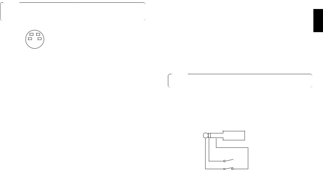
]Y/C-Signal-Eingangsbuchsen [Y/C IN 1, 2, 3, 4, 5]
Führen Sie diesen Buchsen YC-Signale zu, wenn diese als Video-Eingangssignale verwendet werden.
Vorsicht
Schließen Sie kein BNC-Koaxialkabel an die Videosignal-Eingangsbuchsen p an, falls Sie den Y/C-Signal-Eingangsbuchsen ] YC-Signale zuführen. Verwenden Sie entweder FBAS-Signale oder YC-Signale als Video-Eingangssignale.
4 |
3 |
Stift-Nr. |
Signal |
|
1 |
Y GND |
|||
2 |
1 |
|||
2 |
C GND |
|||
|
|
|||
|
|
3 |
Y |
|
|
|
4 |
C |
AVideo-Ausgangsbuchsen [PGM OUT 1, 2]
Zwei Sätze von FBAS-Signalen (BNC), die aus dem Hauptausgangssignal des Bildmischpults und den Wipe-, Mix-, Keyoder anderen hinzugefügten Effekten bestehen, werden von diesen Buchsen ausgegeben.
SVorschau-Ausgangsbuchse [PVW OUT]
Wenn das Bildmischpult für Live-Anwendungen eingesetzt wird, ermöglicht diese Buchse die Vorschau der nächsten Operation. (LOOK AHEAD PREVIEW)
•Während sich der Überblendhebel auf der A-Bus-Seite befindet und A-Bus-Signale ausgegeben werden, werden die B-Bus-Signale an die Buchse PVW OUT ausgegeben, so dass eine Vorschau der Bilder möglich ist.
•Wenn sich die Buchsen PGM OUT im Zustand Key OFF befinden, wird die Buchse PVW OUT in den Zustand Key ON versetzt, so dass eine Vorschau des Key-Synthese-Zustands möglich ist.
Die nachstehende Tabelle zeigt die Beziehung zwischen dem Programmausgang und den Vorschau-Ausgangs-Zuständen.
|
Bus-Auswahl |
Key ON/OFF |
||
PGM OUT |
A-Bus gewählt |
B-Bus gewählt |
Key ON |
Key OFF |
PVW OUT |
B-Bus-Ausgang |
A-Bus-Ausgang |
Key OFF |
Key ON |
DGenlock-Eingangs-/BB-Ausgangsbuchse [GLIN/BBOUT] |
|
|
In Übereinstimmung mit der Einstellung der Schalter SETUP K wird entweder der Genlock-Eingang |
|
|
oder der BB-Ausgang gewählt. |
|
|
Genlock-Eingang: Um Genlock auf das Bildmischpult anzuwenden, ist diese Buchse mit dem |
|
|
|
Signalgenerator oder einem anderen Gerät zu verbinden. |
|
BB-Ausgang: |
In dieser Position wird das BB-Synchronsignal ausgegeben, um Genlock auf eine |
|
|
Kamera oder ein anderes Eingabegerät anzuwenden, indem es mit dem |
DEUTSCH |
|
Bildmischpult synchronisiert wird. In diesem Fall wird das gleiche Signal wie das |
|
|
|
|
von BBOUT F ausgegeben.
FBlack-Burst-Signal-Ausgangsbuchse [BBOUT]
Diese Buchse wird verwendet, um ein an den Live Switcher angeschlossenes Eingabegerät extern zu synchronisieren. Wenn zwei oder mehr Geräte extern synchronisiert werden, verteilen Sie das an sie ausgegebene Black-Burst-Signal mit einem Videoverteiler (VDA).
GY/C-Video-Ausgangsbuchse [PGM Y/C OUT]
Diese Buchse stellt den Y/C-Signalausgang dar, der die gleiche Funktion wie der VideoSignalausgang A hat.
Vorsicht
Aufgrund der bei der Signalverarbeitung ablaufenden Vorgänge weist der Y/C-Videoausgang G eine Phase auf, die gegenüber dem FBAS-Videoausgang A um 1 Zeile verzögert ist.
HEingangsbuchse für externen Auto-Take [EXT TAKE]
Verwenden Sie diese Buchse für externen Auto-Take durch Anlegen einer Kontakteingabe. Die Funktion ist die gleiche wie bei Verwendung der Taste AUTO TAKE u und der Taste KEY AUTO I.Verwenden Sie einen M3.5-Stereo-Einfachkopf-Stecker für den Anschluss an dieses Gerät.
Schließen Sie die Schalter gemäß dem nachstehenden Diagramm an.

 AUTO TAKE
KEY AUTO
16 (G) |
17 (G) |
 Loading...