


Operating Instructions
Excerpted Version
Installation Instructions provided
Model No.
Model No.
HD Integrated Camera
AW-HR140PJ AW-HR140EJ
ENGLISH
Excerpted Version
FRANÇAIS
ESPAÑOL
DEUTSCH
ITALIANO
PУССКИЙ
Before using this product, be sure to read “Read this first!” (pages 4, 18, 19).
This manual contains information excerpted from the Operating Instructions and the Installation Instructions.
For more information, please visit the Panasonic website (http://pro-av.panasonic.net/en/manual/index.html), and refer to the Operating Instruction (PDF).
Avant d’utiliser cet appareil, assurez-vous de lire la section « Lire ces informations en premier ! » (pages 4, 20, 21).
Pour de plus amples informations, visiter le site Web de Panasonic (http://pro-av.panasonic.net/en/manual/index. html) et consulter le mode d’emploi (PDF).
Antes de usar este producto, asegúrese de leer “Lea este documento en primer lugar!” (páginas 4, 22, 23).
Si desea obtener más información, visite el sitio web de Panasonic (http://pro-av.panasonic.net/en/manual/index. html) y consulte las instrucciones de funcionamiento (PDF).
Bitte lesen Sie sorgfältig die „Bitte lesen Sie zuerst diesen Hinweis!“ vor der Nutzung dieses Produkts. (Seiten 5, 24). Weitere Informationen finden Sie auf der Panasonic-Webseite (http://pro-av.panasonic.net/en/manual/index.html) und in der Bedienungsanleitung (PDF).
Prima di utilizzare il prodotto, assicurarsi di leggere “Leggere prima quanto segue!” (pagine 5, 25).
Per maggiori informazioni, per favore visitare il sito web Panasonic (http://pro-av.panasonic.net/en/manual/index. html), e fare riferimento alle istruzioni per l’uso (PDF).
Перед использованием данного прибора ознакомьтесь с информацией в разделе «Прочитайте нижеследующее до начала эксплуатации!» (стр. 5, 26).
Для получения дополнительной информации посетите веб-сайт Panasonic (http://pro-av.panasonic.net/en/ manual/index.html), а также обратитесь кинструкции по эксплуатации (PDF).
Before operating this product, please read the instructions carefully and save this manual for future use.
SS0417TY0 -FJ |
ENGLISH |
|
Printed in Japan DVQX1270ZA
български
Hrvatski
Čeština
Dansk
Nederlands
Eesti
Suomi
Ελληνικά
Magyar
Посетете следния уебсайт относно информация за безопасността и важни уведомления за продукта.
Za sigurnosne informacije i važne obavijesti o proizvodu posjetite sljedeću internetsku stranicu.
Na následujícím webu najdete bezpečnostní informace a důležité poznámky k tomuto produktu.
Besøg følgende webside for sikkerhedsinformation og vigtige bemærkninger vedrørende produktet.
Ga naar de volgende website voor veiligheidsinformatie en belangrijke meldingen over het product.
Toodet puudutava ohutusteabe ja oluliste märkuste saamiseks külastage järgmist veebilehte.
Käy seuraavalla verkkosivulla saadaksesi turvallisuustietoja ja tärkeitä tietoja liittyen laitteeseen.
Για πληροφορίες σχετικά με θέματα ασφάλειας και σημαντικές ειδοποιήσεις που αφορούν το προϊόν σας, επισκεφτείτε τον ιστότοπο που ακολουθεί.
A termékkel kapcsolatos biztonsági információkért és fontos értesítésekért látogasson el az alábbi weboldalra.
Latviešu
Lietuvių
Polski
Português
Română
Slovensky
Slovenščina
Svenska
Lai iegūtu informāciju par drošību un skatītu svarīgus paziņojumus par šo produktu, apmeklējiet tālāk norādīto tīmekļa vietni.
Jei reikia saugos informacijos ir svarbių pranešimų apie gaminį, apsilankykite toliau nurodytoje svetainėje.
Informacje o bezpieczeństwie i ważne informacje o produkcie znajdują się w poniższej witrynie internetowej.
Consulte o seguinte website para as informações de segurança e importantes notificações sobre o produto.
Vizitați următoarea pagină web pentru informaţii de securitate și notificări importante cu privire la produs.
Pre bezpečnostné informácie a dôležité oznámenia súvisiace s produktom navštívte túto webovú stránku.
Za varnostne informacije in pomembna obvestila v zvezi z izdelkom obiščite naslednje spletno mesto.
Besök följande webbplats för säkerhetsinformation och viktiga meddelanden om produkten.
http://pro-av.panasonic.net/en/manual/index.html
Trademarks and registered trademarks
•Microsoft®, Windows®, Windows® 7, Windows® 8, Windows® 8.1,
Windows® 10, Internet Explorer®, ActiveX® and DirectX® are either registered trademarks or trademarks of Microsoft Corporation in the United States and other countries.
•Apple, Mac, OS X, iPhone, iPod Touch, iPad, and Safari are registered trademarks of Apple Inc., in the United States and other countries.
•Android™ is a trademark of Google Inc.
•Intel® and Intel® CoreTM are trademarks or registered trademarks of Intel Corporation in the United States and other countries.
•Adobe® and Reader® are either registered trademarks or trademarks of Adobe Systems Incorporated in the United States and/or other countries.
•Other names of companies and products contained in these
Operating Instructions may be trademarks or registered trademarks of their respective owners.
About copyright and licence
Distributing, copying, disassembling, reverse compiling, reverse engineering, and also exporting in violation of export laws of the software provided with this unit are expressly prohibited.
Abbreviations
The following abbreviations are used in this manual.
•Microsoft® Windows® 7 Professional SP1 32/64-bit is abbreviated to “Windows 7”.
•Microsoft® Windows® 8 Pro 32/64-bit is abbreviated to “Windows 8”.
•Microsoft® Windows® 8.1 Pro 32/64-bit is abbreviated to “Windows 8.1”.
•Microsoft® Windows® 10 Pro 32/64-bit is abbreviated to “Windows 10”.
•Windows® Internet Explorer® 8.0, Windows® Internet Explorer® 9.0, Windows® Internet Explorer® 10.0 and Windows® Internet Explorer® 11.0 are abbreviated to “Internet Explorer”.
For the purposes of this manual, the model numbers of the units are given as listed in the table below.
Model number of unit |
Model number given in |
|
manual |
||
|
||
AW-HR140PJ |
AW-HR140 |
|
AW-HR140EJ |
||
|
||
AW HS50N |
AW HS50 |
|
AW HS50E |
||
|
||
AW RP50N |
AW RP50 |
|
AW RP50E |
||
|
||
AW-RP120G |
AW-RP120 |
|
AK-HRP200G |
AK-HRP200 |
Illustrations and screen displays featured in the manual
•What is shown in the manual’s illustrations and screen displays may differ from how it is actually appears.
•Functions which can be used by Windows only are indicated using the 

 mark.
mark.
•The screenshots are used in accordance with the guidelines of
Microsoft Corporation.
2

Contents
Installation Instructions |
|
Read this first!........................................................................................ |
4 |
Lire ces informations en premier!........................................................ |
4 |
Lea esto primero!................................................................................... |
4 |
Bitte lesen Sie zuerst diesen Hinweis!................................................. |
5 |
Leggere prima quanto segue!............................................................... |
5 |
Прочитайте нижеследующее до начала эксплуатации!................ |
5 |
Installation precautions......................................................................... |
6 |
Before installation.................................................................................. |
8 |
MODE switch settings.......................................................................... |
8 |
How to install and connect the unit...................................................... |
8 |
Performing the installation surface work............................................... |
8 |
Mounting the camera to the installation surface................................... |
8 |
Example of attaching the washer nozzle.............................................. |
9 |
Fixing the drop-prevention wire............................................................ |
9 |
Attaching the cable cover................................................................... |
10 |
Suspended installation....................................................................... |
10 |
Changing the rotation range (suspended installation)........................ |
10 |
Connections......................................................................................... |
12 |
Connections with an HD monitor........................................................ |
12 |
Connections with a controller |
|
(AW-RP50/AW-RP120/AK-HRP200)............................................. |
12 |
System example 1 (Serial control)...................................................... |
13 |
System example 2 (IP control)........................................................... |
14 |
System example 3 (IP image transmission, PoE++).......................... |
15 |
System example 4 |
|
(connection with commercially available controller)....................... |
16 |
System example 5 |
|
(optical fiber system/audio connection using PoE++).................... |
16 |
Appearance........................................................................................... |
17 |
Operating Instructions |
|
Read this first! (For AW-HR140PJ)..................................................... |
18 |
Read this first! (For AW-HR140EJ)..................................................... |
19 |
Lire ces informations en premier ! (Pour AW-HR140PJ).................. |
20 |
Lire ces informations en premier ! (Pour AW-HR140EJ).................. |
21 |
Lea esto primero! (Para AW-HR140PJ).............................................. |
22 |
Lea esto primero! (Para AW-HR140EJ).............................................. |
23 |
Bitte lesen Sie zuerst diesen Hinweis! (Für AW-HR140EJ).............. |
24 |
Leggere prima quanto segue! (Per AW-HR140EJ)............................ |
25 |
Прочитайте нижеследующее до начала эксплуатации! |
|
(Для AW-HR140EJ).......................................................................... |
26 |
Note on grounding.............................................................................. |
27 |
Before use............................................................................................. |
28 |
Overview............................................................................................. |
28 |
Computer requirements...................................................................... |
28 |
Disclaimer of warranty........................................................................ |
29 |
Network security................................................................................. |
29 |
Features................................................................................................ |
|
30 |
Controller supported........................................................................... |
|
31 |
Accessories.......................................................................................... |
|
32 |
Operating precautions......................................................................... |
|
33 |
Parts and their functions..................................................................... |
|
35 |
AW-RP50 (not supplied)...................................................................... |
|
37 |
Network settings.................................................................................. |
|
42 |
Use the Easy IP Setup Software to establish the unit’s settings........ |
42 |
|
Installing the plug-in viewer software.................................................. |
|
43 |
Enable the user authentication function............................................. |
|
43 |
Troubleshooting................................................................................... |
|
44 |
Specifications....................................................................................... |
|
53 |
Index....................................................................................... |
Back cover |
|
3
|
Installation Instructions |
|
|
|
|
|
|
|||
Read this first! |
|
|
|
|||||||
|
|
ENGLISH |
||||||||
|
|
|
|
|
|
|
|
|
|
|
|
|
|
|
|
|
|
|
|
|
|
|
|
|
|
|
|
|
|
|
|
|
|
|
WARNING: |
|
WARNING: |
|
|
||||
|
|
To prevent injury, this apparatus must be securely attached to |
|
Installation should only be performed by qualified installation |
|
|
||||
|
|
the floor/wall in accordance with the installation instructions. |
|
personnel. |
|
|
||||
|
|
|
|
|
|
|
Improper installation may result in the entire apparatus falling |
|
|
|
|
|
|
|
|
|
|
||||
|
|
|
|
|
|
|
down and causing injury. |
|
|
|
|
|
|
|
|
|
|
|
|
|
|
|
|
|
|
|
|
|
|
|
|
|
|
|
|
|
|
|
|
|
|
|
|
|
|
|
|
indicates safety information. |
|
|
|
|
|
|
|
|
|
|
|
|
|
|
|
||
|
|
|
|
|
|
|
|
|
|
|
Lire ces informations en premier! |
|
|
|
|||||||
|
|
FRANÇAIS |
||||||||
|
|
|
|
|
|
|
|
|
|
|
|
|
|
|
|
|
|||||
|
|
|
|
|
|
|
||||
|
|
AVERTISSEMENT: |
|
AVERTISSEMENT: |
|
|
||||
|
|
Pour éviter tout risque de blessures, l’appareil doit être |
|
L’installation ne doit être effectuée que par du personnel |
|
|
||||
|
|
solidement fixé au plancher/mur conformément aux instructions |
|
d’installation qualifié. |
|
|
||||
|
|
d’installation. |
|
Une mauvaise installation peut avoir pour conséquence la chute |
|
|
||||
|
|
|
|
|
|
|
de l’appareil et provoquer des blessures. |
|
|
|
|
|
|
|
|
|
|
|
|||
|
|
|
|
|
|
|
|
|
|
|
|
|
|
|
|
|
|
|
|
|
|
|
|
|
|
|
|
|
|
|
|
|
|
|
|
|
Informations concernant la sécurité. |
|
|
|
|
|
|
|
|
|
|
|
|
|
|
|
||
|
|
|
|
|
|
|
|
|
|
|
Lea esto primero! |
|
|
|
|||||||
|
|
ESPAÑOL |
||||||||
|
|
|
|
|
|
|
|
|
|
|
ADVERTENCIA:
Para evitar heridas, este aparato debe estar firmemente instalado al piso/pared de acuerdo con las instrucciones de instalación.
ADVERTENCIA:
La instalación solamente debe llevarla a cabo personal cualificado.
Una instalación incorrecta podría provocar la caída del dispositivo y causar lesiones.


 indica información de seguridad.
4

Bitte lesen Sie zuerst diesen Hinweis!
Installation Instructions
DEUTSCH
|
|
|
|
|
|
|
|
|
|
|
|
|
|
|
|
|
|
|
|
WARNUNG: |
|
WARNUNG: |
|
|
||
|
|
Um Verletzungen zu verhüten, muss dieser Apparat gemäß |
|
Die Installation darf nur durch qualifiziertes Personal ausgeführt |
|
|
||
|
|
der Installationsanleitung sicher am Boden bzw. an der Wand |
|
werden. |
|
|
||
|
|
befestigt werden. |
|
Fehlerhafte Installation kann zum Herunterfallen des Gerätes |
|
|
||
|
|
|
|
|
|
und zu Verletzungen führen. |
|
|
|
|
|
|
|
|
|||
|
|
|
|
|
|
|
|
|
|
|
|
|
|
|
|
|
|
|
|
|
|
|
|
|
|
|
|
|
|
|
ist die Sicherheitsinformation. |
|
|
|
|
|
|
|
|
|
|
|
|
|
|
|
|
|
|
|
|
|
|
Leggere prima quanto segue! |
|
|
|
||||||
|
|
ITALIANO |
|||||||
|
|
|
|
|
|
|
|
|
|
|
|
|
|
|
|
|
|
|
|
|
|
|
|
|
|
|
|
|
|
|
|
AVVISO: |
|
AVVISO: |
|
|
|
||
|
|
Per prevenire ferite, questo apparecchio deve essere montato |
|
L’installazione deve essere realizzata unicamente da tecnici |
|
|
|||
|
|
saldamente al pavimento/muro in conformità alle istruzioni di |
|
qualificati. |
|
|
|
||
|
|
installazione. |
|
Un’installazione incorretta può risultare nella caduta |
|
|
|
||
|
|
|
|
|
|
dell’apparecchio con conseguenti danni alle persone. |
|
|
|
|
|
|
|
|
|
|
|
||
|
|
|
|
|
|
|
|
|
|
|
|
|
|
|
|
|
|
|
|
|
|
|
|
|
|
|
|
|
|
|
|
|
|
sono le informazioni sulla sicurezza. |
|
|
|
|
|
|
|
|
|
|
|
|
|
|
|
|
|
|
|
|
|
|
|
|
|
Прочитайте нижеследующее до начала эксплуатации! |
|
||||||||
РУССКИЙ |
|||||||||
|
|
|
|
|
|
|
|
|
|
|
|
|
|
|
|
|
|
||
|
|
|
|
|
|
|
|
||
|
|
ОСТОРОЖНО: |
|
ОСТОРОЖНО: |
|
|
|
||
|
|
Во избежание повреждения данный прибор должен |
|
Установка должна выполняться только квалифицированным |
|
|
|||
|
|
быть надежно закреплен на полу/стене в соответствии с |
|
специалистом по установке. |
|
|
|
||
|
|
инструкцией по установке. |
|
Ненадлежащая установка может привести к падению всего |
|
|
|||
|
|
|
|
|
|
аппарата и получению травмы. |
|
|
|
|
|
|
|
|
|
|
|
|
|
|
|
|
|
|
|
|
|
|
|
|
|
|
|
|
|
|
|
|
|
|
|
|
|
|
|
|
|
|
|


 Данный знак обозначает информацию, относящуюся к технике безопасности.
5
Installation Instructions
Installation precautions
Panasonic does not accept any responsibility for accident or damage during installation if procedure in this manual is not followed.
To installation personnel
Read the “Installation Instructions” thoroughly and then perform the operation correctly and safely.
Also, always read the “Read this first!” (→ page 4) of this manual as they contain important information.
After the installation, give the “Installation Instructions” to the customer to save for future use.
Ensure that the installation work complies with the technical standards governing electrical equipment.
This unit is a stand-alone (desktop) device that supports installation outdoors.
This unit is not designed to be used in vehicles.
If the unit will be subjected to extreme vibration, take measures to reduce the vibration before use.
Use the unit with an installation where the unit is suspended from an overhead surface or with a stand alone installation.
Do not use the unit on its side or tilted at an angle.
<NOTE>
•Be absolutely sure to use the supplied mounting bolts (M8) for the unit.
Do not use wood screws, nails, etc.
In the case of a concrete ceiling, secure the unit using anchor bolts
(for M8) or AY plug bolts (for M8).
Recommended clamping torque M8: 11.76 N·m {120 kgf·cm}
•The withdrawal strength of the mounting location for each screw must be at least 1764 N {180 kgf}.
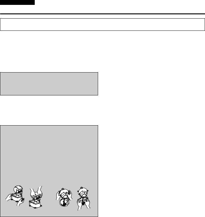
•Do not hold the camera head while undertaking the installation work. Doing so may cause malfunctioning.
OK NG |
OK NG |
Desktop installation |
Hanging installation |
Do not install or use the unit in the following kinds of locations.
•Locations where a chemical agent is used such as a swimming pool
•Locations subject to moisture or oil smoke such as a kitchen
•Locations that have a specific environment that is subject to an inflammable atmosphere or solvents
•Locations where radiation, X-ray, intense radio wave, or strong magnetism is produced
•Locations where seawater will directly splash on the unit and locations where corrosive gas is generated such as volcanic regions and spa areas
•Locations where the temperature is not within the specified range
(→ page 53)
•Locations subject to vibrations, such as on vehicles or above product lines (This unit is not designed to be used in vehicles.)
•Locations subject to sudden changes in temperature, such as near the outdoor unit of an air conditioner (The inside of the front glass may steam up or condensation may form on it.)
Concerning installation in a seashore area
•Salt damage prevention is applied to this unit. However, it is not completely anti-corrosive.
Therefore, consider a place for installation where direct splash of seawater can be avoided.
•Especially when installing this unit in a seashore area or a place where a snow-melting agent is applied, and also where rainwater is avoided, it is recommended to regularly clean and rinse off salt with water.
•In case of installing this unit in a seashore area or a place where a snow-melting agent is applied, regularly check the status of equipment. (Replace the parts as required.)
•Provide a basic structure, pole, etc. for installing the unit that are highly resistant to salt.
Concerning sulfidation caused by rubber products
Do not install the unit near any rubber products (such as gaskets or rubber feet) that contain sulfur. Sulfur components in the rubber product may cause the sulfidation corrosion of parts such as electrical components and terminals, leading to malfunction.
Concerning the installation location
Consult the dealer about the installation area and then select a strong ceiling, floor, or other area for the installation area.
•Mount the unit to a ceiling or floor that is strong enough (one made of concrete).
•Mount the camera unit to a part of the main structure of the building or a part that is sufficiently strong.
•Do not mount the unit on a plaster board or a wooden section because they are too weak. If the unit is unavoidably mounted on such a section, the section shall be sufficiently reinforced.
Concerning waterproofing and dustproofing
When installed correctly, the unit complies with IP65 waterproof and dustproof performance standards.
Be sure to perform wiring and other installation procedures according to the instructions in this document.
Concerning the tightening of anchor bolts and screws
•The anchor bolts and screws must be tightened with an appropriate tightening torque according to the material and strength of the installation area.
•Do not use an impact driver.
Use of an impact driver may damage the screws.
•When tightening an anchor bolt or screw, ensure it is straight. After tightening the screws or anchor bolts, perform checks to ensure that the tightening is sufficient enough so that there is no movement or looseness.
What to avoid to ensure that the unit will perform stably over a prolonged period
•Using the unit for a prolonged period in a location with high temperature and humidity levels will cause its parts to deteriorate and shorten its service life.
•Ensure that a cooling unit or heating unit will not blow any air directly toward the installation location.
6

Installation Instructions
Installation precautions (continued)
Be absolutely sure to use the supplied bolts to install the camera.
•Do not mount the unit by employing any methods other than those specified.
•Do not remodel the mounting screws provided with the unit.
Power switch
This unit does not have a power switch.
When power is supplied, the pan, tilt, zoom, and focus test operations are performed. Do not touch the unit during this time.
Before proceeding with maintenance, be absolutely sure to disconnect the power plug from the power outlet.
Concerning humidity
Install the unit when humidity is low.
If the unit is installed when it is raining or humidity is high, moisture will accumulate inside the unit and the inside of the front glass may steam up.
Heater and defroster
The lower temperature limit for which operation of the unit is guaranteed is –15 °C (5 °F).
The unit is equipped with an internal heater and defroster to enable use in cold environments.
The heater and defroster automatically activate when the approximate internal temperature of the unit reaches 0 °C (32 °F) or below.
However, in harsh temperature environments of –15 °C (5 °F) or below, thawing of snow or frost that forms on the front glass or moving parts may not be possible.
When using the unit in especially cold environments, beware of the ambient temperature and the camera’s internal temperature. When using the unit in temperature environments of –15 °C (5 °F) or below, normal image capture may not be possible immediately after startup.
In such cases, wait for the unit’s heater to warm the inside of the camera (at least 1 hour at –15 °C (5 °F) or below), and then turn the unit off and then on again.
Protection from lightning
When cables are used outdoors, there is a chance that they may be affected by lightning.
In this case, install a lightning arrester close to the unit to prevent it from being affected by lightning, and keep the length of the network cable between the lightning arrester and the unit as short as possible.
Before installation, always disconnect the DC connector
When installing, always use the supplied components. Do not disassemble or modify the wall mount adaptor.
Tightening up the mounting screws
•Tighten up the screws and bolts securely to the degree that is appropriate for each of the materials used in the mounting location and structures.
•After tightening up the screws and bolts, check that there is no unsteadiness and that the parts have been tightened securely.
•Use the specified tools and tighten the screws firmly.
•Tighten up the screws using the specified torque driver. Do not use electrical drivers or impact drivers.
Grounding
Before operating the unit, check that SIGNAL GND has been securely grounded.
If there is a possibility of noise interference
Either wire the cables so that the power cable (ceiling light cord) of AC 100 V*1 (AC 220 V*2 ) or more, and the signal cable are placed at least 1 meter (3.3 ft) apart.
Alternatively run each cable through its own metal conduit. (The metal conduits must be grounded.)
*1 For AW-HR140PJ
*2 For AW-HR140EJ
Radio signal interference
If the unit is positioned near a TV or radio transmitting antenna or a strong electrical field or magnetic field (such as that generated by a motor, transformer or power lines), its images may be distorted and/ or the images may be affected by noise.
When connecting the cables, ensure that the connector areas will not be subject to any load.
Doing so may cause malfunctioning.
Allowing the generated heat to escape
This unit allows the heat generated inside to escape from its surfaces.
Do not install the unit in a location where it will be surrounded by walls or other surfaces and where heat will be trapped.
In addition, the heat is dissipated to the bottom panel which will warm up over time: This is normal and not indicative of any trouble.
PoE++ power supplies
Use a PoE++ (IEEE802.3bt Draft ver.2.0 standard) compatible hub or power supply device.
Make sure installed screws do not touch any wiring inside the ceiling.
Preventing injuries and interference during operation
Take measures to prevent unauthorized persons from touching or approaching the unit to prevent injuries and interference during operation.
When the unit is no longer going to be used, do not leave it lying around, but be absolutely sure to dispose of it properly.
When installing, transferring or disposing of the unit, be absolutely sure to hold it by its pedestal area.
Problems may result if the camera head is held or rotated.
Do not attach a filter, extender or other parts to the unit.
7
Installation Instructions
Before installation
Be sure to configure the switches on the connector panel and bottom of the unit before installing it. Configuring the switches after the unit is installed may prove difficult.
MODE switch settings
The MODE switches are located on the connector panel of the unit.
|
10BASE-T/ |
POWER/ |
|
SDI OUT |
|
RS-422 |
STANDBY |
G/L IN |
2 |
||
100BASE-TX |
|
1/PM |
|||
|
|
|
|
|
MODE |
|
|
12V IN |
|
|
|
|
ACT LINK |
|
|
|
EXT |
|
|
|
|
|
|
|
|
|
|
SIGNAL GND |
|
|
|
|
PUSH |
|
|
|
|
|
AUDIO IN(1/2) |
|
|
MODE switch
Switch |
Function |
|||||||
positions |
||||||||
|
||||||||
1 |
|
|
|
|
|
|
AW series protocol setting (Factory settings) |
|
|
|
|
|
|
|
|||
|
|
|
|
|
|
|
|
|
|
|
|
|
|
|
|
|
|
|
|
|
|
|
|
|
|
|
2 |
|
|
|
|
|
|
Standard protocol setting (baud rate 38400 bps) |
|
|
|
|
|
|
|
|||
|
|
|
|
|
|
|
|
|
|
|
|
|
|
|
|
|
|
|
|
|
|
|
|
|
|
|
3 |
|
|
|
|
|
|
Standard protocol setting (baud rate 9600 bps) |
|
|
|
|
|
|
|
|||
|
|
|
|
|
|
|
|
|
|
|
|
|
|
|
|
|
|
|
|
|
|
|
|
|
|
|
4 |
|
|
|
|
|
|
These are the positions for maintenance. |
|
|
|
|
|
|
|
Do not use the unit while the switches are in these |
||
|
|
|
|
|
|
|
positions. |
|
|
|
|
|
|
|
|
||
|
|
|
|
|
|
|
||
How to install and connect the unit
Be absolutely sure to read through the “Read this first!” (→ pages 4 to 5) and “Installation precautions” (→ pages 6 to 7).
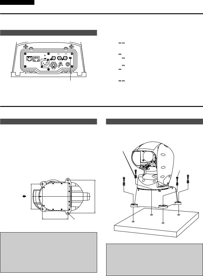
Performing the installation surface work
Perform the work to weld bolts to or drive anchors into the installation surface.
This section describes the case of driving in anchors and fixing with screws.
The dimensions of the installation parts (positions and hole diameter) are shown below.
When fixing the camera directly to the installation surface
Unit: mm (inch)
Mounting the camera to the installation surface When fixing directly to the installation surface
Spring washer and flat washer, x4 of each (supplied accessory)
Unit mounting bolt x4 (supplied accessory)
Camera front |
(6-15/16) |
(9-1/16) |
|
|
|
|
176 |
230 |
|
|
179.7 (7-1/16) |
|
|
4 - ø 8.5 (ø 11/32) |
Image of AW-HR140 viewed from the bottom
<IMPORTANT>
•Check that the mounting installation surface is level.
•When welding anchor bolts to the installation surface, the length of the cut threaded section should be 40 mm (1-9/16 inches) at maximum and 30 mm (1-3/16 inches) at minimum.
Minimum withdrawal strength: 1764 N {180 kgf} per bolt
•Give sufficient consideration to corrosion and similar problems by, for example, using screws with corrosion-resistant coating or performing corking for the mounting screws between the camera or mount bracket and body.
<IMPORTANT>
•Pass the cables through the bottom wiring hole or side wiring hole before putting the camera down on the installation surface.
Recommended clamping torque for mounting unit: 11.76 N·m {120 kgf·cm}
Minimum withdrawal strength of unit mounting bolts or mount bracket mounting screws:
1764 N {180 kgf} per bolt
<NOTE>
•When a washer nozzle will be used, attach it to the washer nozzle mount bracket (supplied accessory) in advance and then fix the washer nozzle mount bracket in place when securing the camera in the preceding “Mounting the camera to the installation surface” (→ page 8).
8

Installation Instructions
How to install and connect the unit (continued)
Example of attaching the washer nozzle
Diameter of nozzle that can be attached: ø 16 mm (ø 5/8 inches)
Washer nozzle mount bracket (supplied accessory)
Fixing the washer nozzle mount bracket
Washer nozzle
Camera front
Fixing the drop-prevention wire
Fix the drop-prevention wire to a part of the main structure of the building or a part that is sufficiently strong (minimum withdrawal strength of 1764 N {180 kgf} or more).
Separately procure M6 mounting bolts suitable for the material of the installation location.
Drop-prevention wire mounting screw (with hexagonal socket, for unit) (supplied accessory)
Drop-prevention wire mounting bolt (M6) (procure separately)
Drop-prevention wire (supplied accessory)
<IMPORTANT>
•Attach the drop-prevention wire so the unit will not hit anybody nearby in the event that it becomes detached.
Unit mounting |
Washer hose |
|
screw x4 (procure |
||
(procure separately) |
||
separately) |
||
Washer nozzle mount bracket |
||
|
||
|
(supplied accessory) |
<NOTE>
•Attach the washer nozzle mount bracket to the side of the camera.
•Perform an installation operation check and then adjust the orientation of the washer nozzle and check that water flows onto the front glass.
•To control the washer, connect pin number 2 and pin number 3 of the EXT connector (→ page 36) to the washer unit and then perform control from the camera menu or controller.
•The washer fluid is not sprayed until the washer hose is filled with washer fluid.
•If the limiter is set more inward than the position to be washed with the washer fluid, the washer will not operate.
•To use the washer function, set [Washer] to [Yes] in the OSD or web screen.
The camera head will move to the position of the washer nozzle, washer fluid will be sprayed for a specific duration, and the camera head will return to the original position.
The wiper also operates momentarily during cleaning.
•The washer position changes depending on whether the installation method is stand-alone or suspended.
Before installing the unit, verify that the camera head moves to the washer nozzle position and confirm that the washer function operates properly.
For details, consult your dealer.
9

Installation Instructions
How to install and connect the unit (continued)
Attaching the cable cover |
Suspended installation |
Pass each of the cables (control cable, optional washer cable, etc.) to be connected to the unit through the supplied cable cover.
Connect each of the cables to the respective connector at the rear of the unit. (Refer to “Connections” (→ pages 12 to 16))
Connect the cable cover to the connector section at the rear of the unit and fix it in place with the four screws.
<IMPORTANT>
•Securely tighten the four screws for attaching the cable cover to the specified torque.
Otherwise, water entering inside will cause the unit to fail or fall.
Separately sold flexible conduit
Cables
Cable cover
Wrap self-adhesive tape around
When installing the unit in an environment in which the cables need to be protected, provide a separately sold flexible conduit.
Select the following recommended flexible conduit or a flexible conduit suitable for the outer diameter (ø 51 mm (ø 2 inches)) of the cable cover back side and protect and waterproof the connections by wrapping selfadhesive tape around.
Separately sold flexible conduit (recommended product)
Manufacturer:
Eco Solutions Company, Panasonic Corporation Part no.:
Panasonic PV flexible conduit, nominal diameter
DMW128N (Panasonic PV flexible conduit)
<NOTE>
•Use weatherproof cables for outdoor wiring.
•If a cable protection tube will not be used, after passing the cables through the cable cover opening, fill the opening with sealing putty and then wrap self-adhesive tape around.
Cables
Cable cover |
|
Sealing putty |
Wrap self-adhesive tape around |
|
When installing the unit suspended by pole installation or other means outdoors, provide a mount bracket of ø 350 mm (ø 13-25/32 inches) or more that matches the dimensions in four places as a shelter against rain and to prevent damage from birds.
For the structure of the mounting part, refer to “Performing the installation surface work” (→ page 8).
Changing the rotation range (suspended installation)
When the unit is installed suspended, the mechanism structure needs to be switched over to enable rotation within the range of 175 degrees left and right.
1. Rotate the |
the figure. |
Camera head
Reinforcement arm cover
Front of body
<NOTE>
•Make sure the reinforcement arm cover is oriented toward the front of the body.
If the work is performed when it is at another position, a load will be applied to the cables inside the unit, leading to a failure.
2.Loosen screw A and remove the reinforcement arm cover from the body.
Reinforcement arm cover
Screw A (M4 with hexagon socket head)
10
Installation Instructions
How to install and connect the unit (continued)
3. Remove the two pin fixing screws and remove the pins at the mechanism endpoint.
Positions of pins for stand-alone installation
Pins at mechanism end point
Pin fixing screws (M2 with hexagon socket heads)
4. Switch over the pins at the mechanism end point between the left and right and then reattach the pin fixing screws.
Positions of pins for suspended installation
Pins at mechanism end point
Pin fixing screws (M2 with hexagon socket heads)
5. Rotate the camera head 180 degrees in the direction of the arrow so that the top and bottom of the camera head are reversed and then attach the reinforcement arm cover to the body.
6. Install the unit suspended.
For the installation procedure, refer to the preceding “Performing the installation surface work” (→ page 8) to “Suspended installation” (→ page 10).
•The rotation range is now switched to 180 degrees so rotation 175 degrees left and right is possible when the unit is in a suspended installation state.
•To return to the stand-alone installation state, perform the work with the procedure in reverse to switch over the pins at the mechanism end point between the left and right.
<NOTE>
•Configurations are set for stand-alone installation under the factory settings.
Be sure to perform the following when using the suspended installation method.
1)Change the pins at mechanism end point
2)Set [Install Position] to [Hanging] in the camera menu (→ PDF page 48 and page 80)
3)Restart the unit (disconnect the power supply to the unit before
connecting it again)
Perform operations similar to the above for stand-alone installation when switching back from a suspended installation to a stand-alone installation.
•Selecting the wrong setting for [Install Position] may result in contact at the edges of the movement range and malfunction.
Camera head
Reinforcement arm cover
11
Installation Instructions
Connections
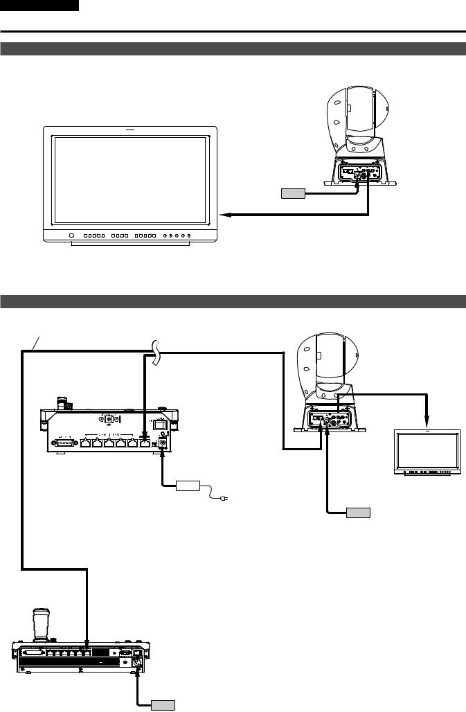
Connections with an HD monitor
HD Integrated Camera
AW-HR140
External DC power supply
HD-SDI signal
HD monitor
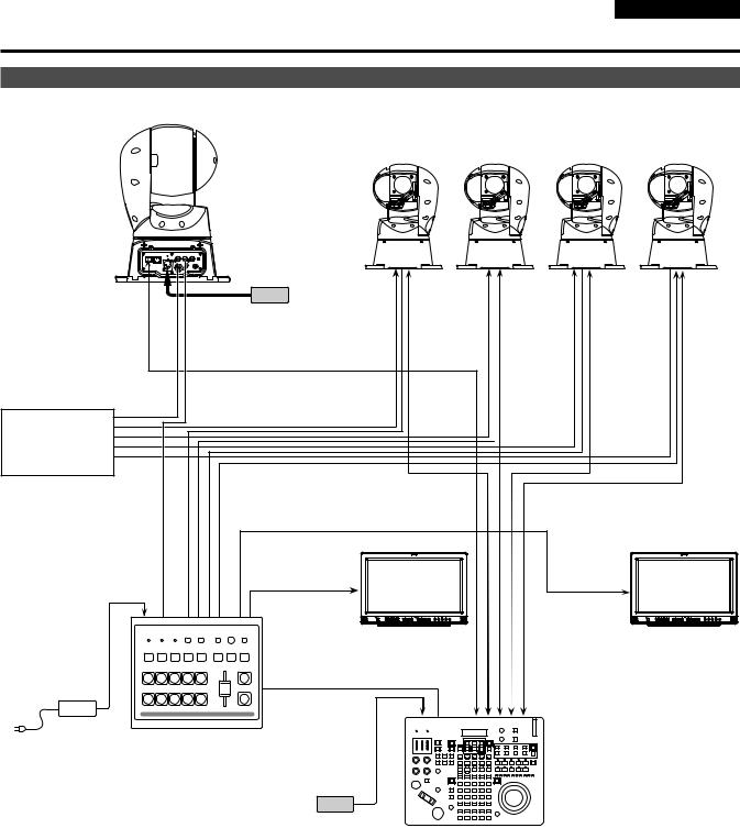
Connections with a controller (AW-RP50/AW-RP120/AK-HRP200)
|
HD Integrated Camera |
|
LAN cable (crossover cable) |
AW-HR140 |
|
Pan-tilt head/ |
||
|
||
|
camera control signals |
|
Remote Camera Controller |
SDI signal |
|
AW-RP50 |
||
|
Monitor
Accessory
AC adaptor
External DC power supply
Remote Camera Controller AW-RP120
External DC power supply
12
Installation Instructions
Connections (continued)
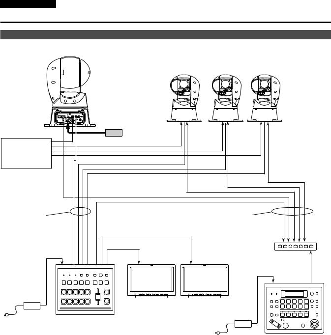
System example 1 (Serial control)
HD Integrated Camera
AW-HR140
HD Integrated Camera AW-HR140
External DC
power supply
RS-422 connector
Genlock signal generator
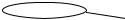 Pan-tilt head and camera control signal (LAN straight cable)
SDI video signal 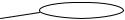
Monitor 1
Monitor 2
Monitor |
Monitor |
System TALLY
Accessory |
Compact Live Switcher |
AC adaptor |
AW HS50 |
External DC |
|
power supply |
Remote Camera Controller |
|
AW-RP120 |
13
Installation Instructions
Connections (continued)
System example 2 (IP control)
HD Integrated Camera
AW-HR140
HD Integrated Camera
AW-HR140
|
External DC |
|
|
|
power supply |
|
|
LAN connector |
|
|
|
Genlock signal |
|
|
|
generator |
|
|
|
SDI video signal |
|
LAN cable |
|
|
|
(straight cable) |
|
|
|
Monitor 2 |
|
|
|
Switching hub |
|
|
Monitor 1 |
|
LAN cable |
|
|
|
|
|
|
|
(straight cable) |
|
Monitor |
Monitor |
|
Accessory |
Compact Live Switcher |
|
|
AC adaptor |
AW HS50 |
|
|
|
|
Accessory |
Remote Camera Controller |
|
|
AC adaptor |
AW RP50 |
14
Installation Instructions
Connections (continued)
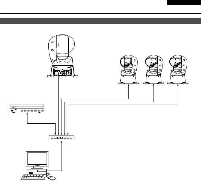
System example 3 (IP image transmission, PoE++)
HD Integrated Camera
AW-HR140
HD Integrated Camera
AW-HR140
LAN connector
Network Recorder
WJ-NV300/4
LAN cable (straight cable)
PoE++ compatible switching hub or injector
Personal computer
15
Installation Instructions
Connections (continued)
System example 4 (connection with commercially available controller)
HD Integrated Camera AW-HR140
Serial connector
Communication connector
|
|
|
|
External DC |
|
|
|
|
|
Commercially |
|
|
power supply |
|
|
|
|||
|
|
|||
available controller |
|
|
||
• Configure the MODE switches at the connector panel of the unit. |
|
|||
For details on the MODE switches, see “MODE switch settings” (→ page 8). |
|
|||
•Configure the following items in the camera menu.
1.Display [System] menu - [Protocol] - [Model Select].
2.Select [SEVIHD1], [SBRC300], or [SBRCZ330] for the protocol type.
<NOTE>
• The unit is not equipped with a daisy-chain connection function for connecting multiple units.
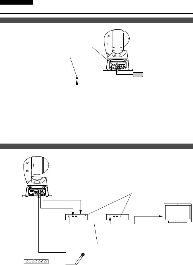
System example 5 (optical fiber system/audio connection using PoE++)
HD Integrated Camera AW-HR140
|
SDI/optical signal conversion module |
DC power supply |
|
SDI signal |
SDI signal |
|
Transmitter |
Receiver |
SDI monitor |
(transmitting side) |
(receiving side) |
|
|
Optical fiber cable |
|
DC power supply |
|
|
Audio signal (CH1/CH2) |
|
|
PoE++ compatible switching hub or injector
Line input is used for the unit’s external audio input.
When connecting a microphone or other devices with different levels, match the level using an amp, for example.
16

Installation Instructions
Appearance
Unit: mm (inch)
257.5 (10-1/8)
285.6 (11-1/4) |
275.6 (10-27/32) |
357.1 (14-1/16) |
(4-1/32) |
ɸ2) |
102 |
51 ( |
|
ɸ |
|
356.6 (14-1/32) |
|
396.9 (15-19/32) |
(6-15/16) |
(9-1/16) |
176 |
230 |
|
|
11/32) |
|
|
ɸ |
|
8 |
|
|
. |
|
|
5 |
|
4 |
|
( |
– |
|
|
ɸ |
|
|
179.7 (7-1/16)
17
 Loading...