


Panasonic AN80L22RMS, AN80L21RMS, AN80L20RMS, AN80L19RMS, AN80L18RMS Datasheet
...
Voltage Regulators
AN80LXXRMS Series
Low-drop type positive output voltage regulator IC
■ Overview
The AN80LXXRMS series is 0.15 A output low-drop output type positive voltage regulator IC with resetting function. 20 classifications of output voltages, 1.8 V, 1.9 V, 2.0 V, 2.1 V, 2.2 V, 2.5 V, 2.8 V, 2.9 V, 3.0 V, 3.1 V, 3.2 V, 3.3 V, 3.4 V, 3.5 V, 3.6 V, 4.8 V, 4.9 V, 5.0 V, 5.1 V and 5.2 V are available. In addition, it is adopting the surface mounting type package (Mini 5-pin plastic package), so that it is most suited for miniaturization and weight reduction of set equipment.
■ Features
•Minimum input and output voltage difference : 0.4 V max.
•High precision output voltage : (allowance : ± 3%)
•Built-in reset function terminal (High : Active)
•Built-in overcurrent limiting circuit
•Built-in circuit for limiting rush current at input voltage rising time
•Output voltage : 1.8 V to 5.2 V
|
|
|
|
2.8 |
+0.2 |
Unit : mm |
|
|
|
|
|
–0.3 |
|
|
|
0.65±0.15 |
|
1.5 |
+0.25 |
0.65±0.15 |
|||
|
–0.05 |
||||||
|
|
|
5 |
|
|
1 |
1.45±0.1 |
+0.2 |
1.9±0.1 |
0.95 0.95 |
4 |
|
|
|
|
|
|
|
|
||||
–0.052.9 |
3 |
|
|
2 |
|||
|
|
|
|
|
|
+0.1 –0.05 |
|
|
|
|
|
|
|
0.3 |
|
+0.2 |
|
|
|
|
|
|
+0.1 |
1.1 –0.1 |
0.8 |
|
|
|
|
|
0.16–0.06 |
|
|
|
0.1 |
0.1 to 0.3 |
0.4±0.2 |
||
|
|
|
|
|
|||
|
|
|
0 to |
|
|
|
|
|
|
|
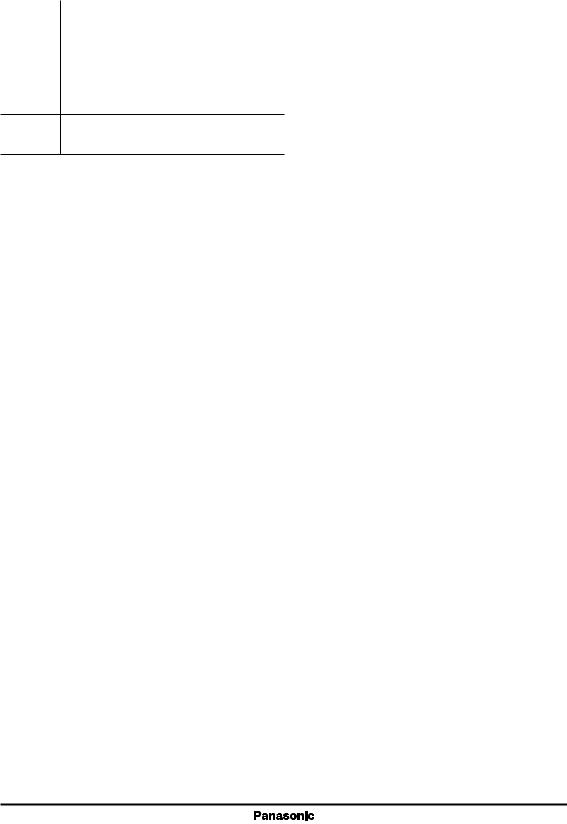
Mini-type 5-pin |
|
|
||
Type name indication symbol : XX
■ Applications
•Cellular phone, PHS, analog cordless phone, other small sized potable equipment
■ Block diagram
IN |
1 |
|
2 |
OUT |
|
|
|
||
|
|
Current |
|
|
|
|
source |
|
|
CONT |
5 |
Start / |
Error |
|
|
Stop |
|
||
|
|
|
||
|
|
|
amp. |
|
|
|
Bandgap |
3 |
N.C. |
|
|
reference |
|
|
|
|
|
|
|
|
|
4 |
|
|
|
|
GND |
|
|
1

AN80LXXRMS Series |
|
|
|
|
Voltage Regulators |
|||
■ Output Voltage Characteristics at IOUT = 50 mA, Ta = 25°C |
|
|
|
|
||||
|
|
|
|
|
|
|
|
|
Type No. |
Output V |
Conditions |
min. |
|
typ. |
max. |
Unit |
Marking |
|
|
|
|
|
|
|
|
|
AN80L18RMS |
1.8 |
VIN = 2.8 V |
1.746 |
|
1.8 |
1.854 |
V |
BA |
AN80L19RMS |
1.9 |
2.9 |
1.843 |
|
1.9 |
1.957 |
|
BB |
AN80L20RMS |
2.0 |
3.0 |
1.940 |
|
2.0 |
2.060 |
|
BC |
AN80L21RMS |
2.1 |
3.1 |
2.037 |
|
2.1 |
2.163 |
|
BD |
AN80L22RMS |
2.2 |
3.2 |
2.134 |
|
2.2 |
2.266 |
|
BE |
AN80L25RMS |
2.5 |
3.5 |
2.452 |
|
2.5 |
2.575 |
|
BW |
AN80L28RMS |
2.8 |
3.8 |
2.716 |
|
2.8 |
2.884 |
|
BF |
AN80L29RMS |
2.9 |
3.9 |
2.813 |
|
2.9 |
2.987 |
|
BG |
AN80L30RMS |
3.0 |
4.0 |
2.910 |
|
3.0 |
3.090 |
|
BH |
AN80L31RMS |
3.1 |
4.1 |
3.007 |
|
3.1 |
3.193 |
|
BJ |
AN80L32RMS |
3.2 |
4.2 |
3.104 |
|
3.2 |
3.296 |
|
BK |
AN80L33RMS |
3.3 |
4.3 |
3.201 |
|
3.3 |
3.399 |
|
BL |
AN80L34RMS |
3.4 |
4.4 |
3.298 |
|
3.4 |
3.502 |
|
BM |
AN80L35RMS |
3.5 |
4.5 |
3.395 |
|
3.5 |
3.605 |
|
BN |
AN80L36RMS |
3.6 |
4.6 |
3.492 |
|
3.6 |
3.708 |
|
BP |
AN80L48RMS |
4.8 |
5.8 |
4.656 |
|
4.8 |
4.944 |
|
BQ |
AN80L49RMS |
4.9 |
5.9 |
4.753 |
|
4.9 |
5.047 |
|
BR |
AN80L50RMS |
5.0 |
6.0 |
4.850 |
|
5.0 |
5.150 |
|
BS |
AN80L51RMS |
5.1 |
6.1 |
4.947 |
|
5.1 |
5.253 |
|
BT |
AN80L52RMS |
5.2 |
6.2 |
5.044 |
|
5.2 |
5.356 |
|
BU |
|
|
|
|
|
|
|
|
|
BA
(Marking example : AN80L18RMS)
2
Voltage Regulators |
AN80LXXRMS Series |
|
Common to the AN80LXXRMS Series |
|
|
■ Pin Descriptions |
|
|
|
|
|
Pin No. |
Description |
|
|
|
|
1 |
Input voltage pin |
|
|
|
|
2 |
Output voltage pin |
|
|
|
|
3 |
N.C. pin |
|
|
|
|
4 |
Grounding pin |
|
5Control pin
("High" → operation "Low" → stop)
■Absolute Maximum Ratings
Parameter |
Symbol |
Rating |
Unit |
|
|
|
|
Supply voltage *1 |
V |
14.6 |
V |
|
CC |
|
|
Supply current |
ICC |
300 |
mA |
Power dissipation *3 |
PD |
78 |
mW |
Operating ambient temperature *2 |
Topr |
−30 to +85 |
°C |
Storage temperature *2 |
Tstg |
−55 to +150 |
°C |
Note) *1 : There may be a case of the device destruction when the output (VOUT) and the grounding (GND), or the output (VOUT) and input (VIN) are short-circuited.
*2 : All items are at Ta = 25°C, except for the parameter of operating ambient temperature and storage temperature. *3 : Topr = Power dissipation for IC alone without heat sink at + 85°C.
3

AN80LXXRMS Series |
|
|
Voltage Regulators |
|
AN80L18RMS (1.8 V) |
|
|
|
|
■ Recommended Operating Range |
|
|
|
|
|
|
|
|
|
Parameter |
Symbol |
Range |
|
Unit |
|
|
|
|
|
Supply voltage |
VCC |
2.2 to 14.5 |
|
V |
■ Electrical Characteristics at Ta = 25°C
Note) Unless otherwise specially provided, shorten each test time (within 10 ms) so that the test is conducted under the condition that the drift due to the temperature increase in the chip junction part can be neglected. CIN = 0.1 µF, COUT = 10 µF
Parameter |
Symbol |
Conditions |
Min |
Typ |
Max |
Unit |
|
|
|
|
|
|
|
Output voltage |
VOUT |
VIN = 2.8 V, IOUT = 50 mA |
1.746 |
1.8 |
1.854 |
V |
Input stability 1 |
REGIN1 |
VIN = 2.8 V → 14.5 V, IOUT = 50 mA |
|
10 |
50 |
mV |
Input stability 2 |
REGIN2 |
VIN = 2.8 V → 9 V, IOUT = 50 mA |
|
5 |
20 |
mV |
|
|
|
|
|
|
|
Load stability *1 |
REGLOA |
VIN = 2.8 V, IOUT = 0 mA → 150 mA |
|
50 |
150 |
mV |
Peak output current *2 |
IPEAK |
VIN = 2.8 V, The output current value |
180 |
240 |
|
mA |
|
|
decreases by 5% from the value |
|
|
|
|
|
|
when VOUT is at IOUT = 50 mA. |
|
|
|
|
|
|
|
|
|
|
|
Bias current without load |
IBIAS |
VIN = 2.8 V, IOUT = 0 mA |
|
|
350 |
µA |
Bias current fluctuation with load |
IBIAS |
VIN = 2.8 V, IOUT = 0 mA → 150 mA |
|
|
5 |
mA |
Standby consumption current |
ISTB |
VIN = 10 V, VCONT = 0 V |
|
|
0.1 |
µA |
Bias current before starting |
IRUSH |
VIN = 1.5 V, IOUT = 0 mA |
|
1.5 |
5 |
mA |
regulation |
|
|
|
|
|
|
|
|
|
|
|
|
|
Ripple rejection ratio |
R.R. |
1 Vrms, f = 120 Hz, IOUT = 10 mA |
62 |
70 |
|
dB |
|
|
|
|
|
|
|
Minimum input and |
VDIF(min)1 |
VIN = 1.5 V, IOUT = 0 mA |
|
0.1 |
0.2 |
V |
output voltage difference 1 |
|
|
|
|
|
|
|
|
|
|
|
|
|
Minimum input and |
VDIF(min)2 |
VIN = 2.1 V, IOUT = 150 mA |
|
|
0.4 |
V |
output voltage difference 2 |
|
|
|
|
|
|
|
|
|
|
|
|
|
Control terminal threshold high voltage |
VCONTH |
VIN = 2.8 V, IOUT = 50 mA |
|
|
1.50 |
V |
Control terminal threshold low voltage |
VCONTL |
VIN = 2.8 V, IOUT = 50 mA |
0.30 |
|
|
V |
Control terminal current |
ICONT |
VIN = 2.8 V, IOUT = 50 mA |
|
|
30 |
µA |
|
|
VCONT = 1.8 V |
|
|
|
|
Note) *1 : 1.0 Ω
*2 : Peak output current : The output current when the output voltage has been decreased by 5% from the value at the time of the output current is 50 mA due to the overcurrent protection.
•Design reference data
Note) The following values are typical and not guaranteed values.
Parameter |
Symbol |
|
Conditions |
Min |
Typ |
Max |
Unit |
|
|
|
|
|
|
|
|
|
|
Output noise voltage |
VNO |
|
10Hz ≤ f ≤ 100kHz, IOUT = 10 mA |
|
38 |
|
µV |
|
Output voltage temperature |
1 dVOUT |
|
VIN = 2.8 V, IOUT = 0 mA |
|
90 |
|
ppm/°C |
|
|
VOUT |
|
|
− 30°C ≤ Ta ≤ + 85°C |
|
|
|
|
coefficient |
dT |
|
|
|
|
|||
Output rise time |
tON |
|
VIN = 2.8 V, IOUT = 50 mA |
|
0.10 |
|
ms |
|
|
|
|
|
VCONT = 0 V → 1.8 V, CIN = 0.1 µF |
|
|
|
|
|
|
|
|
COUT = 10 µF, VOUT = 90% |
|
|
|
|
Note) *1 : Refer to ■ Technical Information " • Output rise time characteristics".
4

Voltage Regulators |
|
|
AN80LXXRMS Series |
|
AN80L19RMS (1.9 V) |
|
|
|
|
■ Recommended Operating Range |
|
|
|
|
|
|
|
|
|
Parameter |
Symbol |
Range |
|
Unit |
|
|
|
|
|
Supply voltage |
VCC |
2.3 to 14.5 |
|
V |
■ Electrical Characteristics at Ta = 25°C
Note) Unless otherwise specially provided, shorten each test time (within 10 ms) so that the test is conducted under the condition that the drift due to the temperature increase in the chip junction part can be neglected. CIN = 0.1 µF, COUT = 10 µF
Parameter |
Symbol |
Conditions |
Min |
Typ |
Max |
Unit |
|
|
|
|
|
|
|
Output voltage |
VOUT |
VIN = 2.9 V, IOUT = 50 mA |
1.843 |
1.9 |
1.957 |
V |
Input stability 1 |
REGIN1 |
VIN = 2.9 V → 14.5 V, IOUT = 50 mA |
|
10 |
50 |
mV |
Input stability 2 |
REGIN2 |
VIN = 2.9 V → 9 V, IOUT = 50 mA |
|
5 |
20 |
mV |
|
|
|
|
|
|
|
Load stability *1 |
REGLOA |
VIN = 2.9 V, IOUT = 0 mA → 150 mA |
|
50 |
150 |
mV |
Peak output current *2 |
IPEAK |
VIN = 2.9 V, The output current value |
180 |
240 |
|
mA |
|
|
decreases by 5% from the value |
|
|
|
|
|
|
when VOUT is at IOUT = 50 mA. |
|
|
|
|
|
|
|
|
|
|
|
Bias current without load |
IBIAS |
VIN = 2.9 V, IOUT = 0 mA |
|
|
350 |
µA |
Bias current fluctuation with load |
IBIAS |
VIN = 2.9 V, IOUT = 0 mA → 150 mA |
|
|
5 |
mA |
Standby consumption current |
ISTB |
VIN = 10 V, VCONT = 0 V |
|
|
0.1 |
µA |
Bias current before starting |
IRUSH |
VIN = 1.6 V, IOUT = 0 mA |
|
1.5 |
5 |
mA |
regulation |
|
|
|
|
|
|
|
|
|
|
|
|
|
Ripple rejection ratio |
R.R. |
1 Vrms, f = 120 Hz, IOUT = 10 mA |
62 |
70 |
|
dB |
|
|
|
|
|
|
|
Minimum input and |
VDIF(min)1 |
VIN = 1.6 V, IOUT = 0 mA |
|
0.1 |
0.2 |
V |
output voltage difference 1 |
|
|
|
|
|
|
|
|
|
|
|
|
|
Minimum input and |
VDIF(min)2 |
VIN = 2.2 V, IOUT = 150 mA |
|
|
0.4 |
V |
output voltage difference 2 |
|
|
|
|
|
|
|
|
|
|
|
|
|
Control terminal threshold high voltage |
VCONTH |
VIN = 2.9 V, IOUT = 50 mA |
|
|
1.50 |
V |
Control terminal threshold high voltage |
VCONTH |
VIN = 2.9 V, IOUT = 50 mA |
0.30 |
|
|
V |
Control terminal current |
ICONT |
VIN = 2.9 V, IOUT = 50 mA |
|
|
30 |
µA |
|
|
VCONT = 1.8 V |
|
|
|
|
Note) *1 : 1.0 Ω
*2 : Peak output current : The output current when the output voltage has been decreased by 5% from the value at the time of the output current is 50 mA due to the overcurrent protection.
•Design reference data
Note) The following values are typical and not guaranteed values.
Parameter |
Symbol |
|
Conditions |
Min |
Typ |
Max |
Unit |
||
|
|
|
|
|
|
|
|
|
|
Output noise voltage |
VNO |
|
10Hz ≤ f ≤ 100kHz, IOUT = 10 mA |
|
40 |
|
µV |
||
Output voltage temperature |
1 dVOUT |
|
VIN = 2.9 V, IOUT = 0 mA |
|
90 |
|
ppm/°C |
||
|
VOUT |
|
|
− 30°C ≤ Ta ≤ + 85°C |
|
|
|
|
|
coefficient |
dT |
|
|
|
|
||||
Output rise time |
tON |
|
VIN = 2.9 V, IOUT = 50 mA |
|
0.10 |
|
ms |
||
|
|
|
|
VCONT = 0 V → 1.8 V, CIN = 0.1 µF |
|
|
|
|
|
|
|
|
|
COUT = 10 µF, VOUT = 90% |
|
|
|
|
|
Note) *1 : Refer to ■ Technical Information " • Output rise time characteristics". |
|
|
|
|
|||||
|
|
|
|
|
|
|
|
|
|
|
|
|
|
|
|
|
|
|
5 |
|
|
|
|
|
|
|
|
|
|
|
|
|
|
|
|
|
|
|
|

AN80LXXRMS Series |
|
|
Voltage Regulators |
|
AN80L20RMS (2.0 V) |
|
|
|
|
■ Recommended Operating Range |
|
|
|
|
|
|
|
|
|
Parameter |
Symbol |
Range |
|
Unit |
|
|
|
|
|
Supply voltage |
VCC |
2.4 to 14.5 |
|
V |
■ Electrical Characteristics at Ta = 25°C
Note) Unless otherwise specially provided, shorten each test time (within 10 ms) so that the test is conducted under the condition that the drift due to the temperature increase in the chip junction part can be neglected. CIN = 0.1 µF, COUT = 10 µF
Parameter |
Symbol |
Conditions |
Min |
Typ |
Max |
Unit |
|
|
|
|
|
|
|
Output voltage |
VOUT |
VIN = 3.0 V, IOUT = 50 mA |
1.940 |
2.0 |
2.060 |
V |
Input stability 1 |
REGIN1 |
VIN = 3.0 V → 14.5 V, IOUT = 50 mA |
|
10 |
50 |
mV |
Input stability 2 |
REGIN2 |
VIN = 3.0 V → 9 V, IOUT = 50 mA |
|
5 |
20 |
mV |
|
|
|
|
|
|
|
Load stability *1 |
REGLOA |
VIN = 3.0 V, IOUT = 0 mA → 150 mA |
|
50 |
150 |
mV |
Peak output current *2 |
IPEAK |
VIN = 3.0 V, The output current value |
180 |
240 |
|
mA |
|
|
decreases by 5% from the value |
|
|
|
|
|
|
when VOUT is at IOUT = 50 mA. |
|
|
|
|
|
|
|
|
|
|
|
Bias current without load |
IBIAS |
VIN = 3.0 V, IOUT = 0 mA |
|
|
350 |
µA |
Bias current fluctuation with load |
IBIAS |
VIN = 3.0 V, IOUT = 0 mA → 150 mA |
|
|
5 |
mA |
Standby consumption current |
ISTB |
VIN = 10 V, VCONT = 0 V |
|
|
0.1 |
µA |
Bias current before starting |
IRUSH |
VIN = 1.7 V, IOUT = 0 mA |
|
1.5 |
5 |
mA |
regulation |
|
|
|
|
|
|
|
|
|
|
|
|
|
Ripple rejection ratio |
R.R. |
1 Vrms, f = 120 Hz, IOUT = 10 mA |
62 |
70 |
|
dB |
|
|
|
|
|
|
|
Minimum input and |
VDIF(min)1 |
VIN = 1.7 V, IOUT = 0 mA |
|
0.1 |
0.2 |
V |
output voltage difference 1 |
|
|
|
|
|
|
|
|
|
|
|
|
|
Minimum input and |
VDIF(min)2 |
VIN = 2.3 V, IOUT = 150 mA |
|
|
0.4 |
V |
output voltage difference 2 |
|
|
|
|
|
|
|
|
|
|
|
|
|
Control terminal threshold high voltage |
VCONTH |
VIN = 3.0 V, IOUT = 50 mA |
|
|
1.50 |
V |
Control terminal threshold high voltage |
VCONTH |
VIN = 3.0 V, IOUT = 50 mA |
0.30 |
|
|
V |
Control terminal current |
ICONT |
VIN = 3.0 V, IOUT = 50 mA |
|
|
30 |
µA |
|
|
VCONT = 1.8 V |
|
|
|
|
Note) *1 : 1.0 Ω
*2 : Peak output current : The output current when the output voltage has been decreased by 5% from the value at the time of the output current is 50 mA due to the overcurrent protection.
•Design reference data
Note) The following values are typical and not guaranteed values.
Parameter |
Symbol |
|
Conditions |
Min |
Typ |
Max |
Unit |
|
|
|
|
|
|
|
|
|
|
Output noise voltage |
VNO |
|
10Hz ≤ f ≤ 100kHz, IOUT = 10 mA |
|
42 |
|
µV |
|
Output voltage temperature |
1 dVOUT |
|
VIN = 3.0 V, IOUT = 0 mA |
|
90 |
|
ppm/°C |
|
|
VOUT |
|
|
− 30°C ≤ Ta ≤ + 85°C |
|
|
|
|
coefficient |
dT |
|
|
|
|
|||
Output rise time |
tON |
|
VIN = 3.0 V, IOUT = 50 mA |
|
0.10 |
|
ms |
|
|
|
|
|
VCONT = 0 V → 1.8 V, CIN = 0.1 µF |
|
|
|
|
|
|
|
|
COUT = 10 µF, VOUT = 90% |
|
|
|
|
Note) *1 : Refer to ■ Technical Information " • Output rise time characteristics".
6

Voltage Regulators |
|
|
AN80LXXRMS Series |
|
AN80L21RMS (2.1 V) |
|
|
|
|
■ Recommended Operating Range |
|
|
|
|
|
|
|
|
|
Parameter |
Symbol |
Range |
|
Unit |
|
|
|
|
|
Supply voltage |
VCC |
2.5 to 14.5 |
|
V |
■ Electrical Characteristics at Ta = 25°C
Note) Unless otherwise specially provided, shorten each test time (within 10 ms) so that the test is conducted under the condition that the drift due to the temperature increase in the chip junction part can be neglected. CIN = 0.1 µF, COUT = 10 µF
Parameter |
Symbol |
Conditions |
Min |
Typ |
Max |
Unit |
|
|
|
|
|
|
|
Output voltage |
VOUT |
VIN = 3.1 V, IOUT = 50 mA |
2.037 |
2.1 |
2.163 |
V |
Input stability 1 |
REGIN1 |
VIN = 3.1 V → 14.5 V, IOUT = 50 mA |
|
10 |
50 |
mV |
Input stability 2 |
REGIN2 |
VIN = 3.1 V → 9 V, IOUT = 50 mA |
|
5 |
20 |
mV |
|
|
|
|
|
|
|
Load stability *1 |
REGLOA |
VIN = 3.1 V, IOUT = 0 mA → 150 mA |
|
50 |
150 |
mV |
Peak output current *2 |
IPEAK |
VIN = 3.1 V, The output current value |
180 |
240 |
|
mA |
|
|
decreases by 5% from the value |
|
|
|
|
|
|
when VOUT is at IOUT = 50 mA. |
|
|
|
|
|
|
|
|
|
|
|
Bias current without load |
IBIAS |
VIN = 3.1 V, IOUT = 0 mA |
|
|
350 |
µA |
Bias current fluctuation with load |
IBIAS |
VIN = 3.1 V, IOUT = 0 mA → 150 mA |
|
|
5 |
mA |
Standby consumption current |
ISTB |
VIN = 10 V, VCONT = 0 V |
|
|
0.1 |
µA |
Bias current before starting |
IRUSH |
VIN = 1.8 V, IOUT = 0 mA |
|
1.5 |
5 |
mA |
regulation |
|
|
|
|
|
|
|
|
|
|
|
|
|
Ripple rejection ratio |
R.R. |
1 Vrms, f = 120 Hz, IOUT = 10 mA |
61 |
69 |
|
dB |
|
|
|
|
|
|
|
Minimum input and |
VDIF(min)1 |
VIN = 1.8 V, IOUT = 0 mA |
|
0.1 |
0.2 |
V |
output voltage difference 1 |
|
|
|
|
|
|
|
|
|
|
|
|
|
Minimum input and |
VDIF(min)2 |
VIN = 2.4 V, IOUT = 150 mA |
|
|
0.4 |
V |
output voltage difference 2 |
|
|
|
|
|
|
|
|
|
|
|
|
|
Control terminal threshold high voltage |
VCONTH |
VIN = 3.1 V, IOUT = 50 mA |
|
|
1.50 |
V |
Control terminal threshold high voltage |
VCONTH |
VIN = 3.1 V, IOUT = 50 mA |
0.30 |
|
|
V |
Control terminal current |
ICONT |
VIN = 3.1 V, IOUT = 50 mA |
|
|
30 |
µA |
|
|
VCONT = 1.8 V |
|
|
|
|
Note) *1 : 1.0 Ω
*2 : Peak output current : The output current when the output voltage has been decreased by 5% from the value at the time of the output current is 50 mA due to the overcurrent protection.
•Design reference data
Note) The following values are typical and not guaranteed values.
Parameter |
Symbol |
|
Conditions |
Min |
Typ |
Max |
Unit |
||
|
|
|
|
|
|
|
|
|
|
Output noise voltage |
VNO |
|
10Hz ≤ f ≤ 100kHz, IOUT = 10 mA |
|
44 |
|
µV |
||
Output voltage temperature |
1 dVOUT |
|
VIN = 3.1 V, IOUT = 0 mA |
|
90 |
|
ppm/°C |
||
|
VOUT |
|
|
− 30°C ≤ Ta ≤ + 85°C |
|
|
|
|
|
coefficient |
dT |
|
|
|
|
||||
Output rise time |
tON |
|
VIN = 3.1 V, IOUT = 50 mA |
|
0.10 |
|
ms |
||
|
|
|
|
VCONT = 0 V → 1.8 V, CIN = 0.1 µF |
|
|
|
|
|
|
|
|
|
COUT = 10 µF, VOUT = 90% |
|
|
|
|
|
Note) *1 : Refer to ■ Technical Information " • Output rise time characteristics". |
|
|
|
|
|||||
|
|
|
|
|
|
|
|
|
|
|
|
|
|
|
|
|
|
|
7 |
|
|
|
|
|
|
|
|
|
|
|
|
|
|
|
|
|
|
|
|
AN80LXXRMS Series |
|
|
Voltage Regulators |
|
AN80L22RMS (2.2 V) |
|
|
|
|
■ Recommended Operating Range |
|
|
|
|
|
|
|
|
|
Parameter |
Symbol |
Range |
|
Unit |
|
|
|
|
|
Supply voltage |
VCC |
2.6 to 14.5 |
|
V |
■ Electrical Characteristics at Ta = 25°C
Note) Unless otherwise specially provided, shorten each test time (within 10 ms) so that the test is conducted under the condition that the drift due to the temperature increase in the chip junction part can be neglected. CIN = 0.1 µF, COUT = 10 µF
Parameter |
Symbol |
Conditions |
Min |
Typ |
Max |
Unit |
|
|
|
|
|
|
|
Output voltage |
VOUT |
VIN = 3.2 V, IOUT = 50 mA |
2.134 |
2.2 |
2.266 |
V |
Input stability 1 |
REGIN1 |
VIN = 3.2 V → 14.5 V, IOUT = 50 mA |
|
10 |
50 |
mV |
Input stability 2 |
REGIN2 |
VIN = 3.2 V → 9 V, IOUT = 50 mA |
|
5 |
20 |
mV |
|
|
|
|
|
|
|
Load stability *1 |
REGLOA |
VIN = 3.2 V, IOUT = 0 mA → 150 mA |
|
50 |
150 |
mV |
Peak output current *2 |
IPEAK |
VIN = 3.2 V, The output current value |
180 |
240 |
|
mA |
|
|
decreases by 5% from the value |
|
|
|
|
|
|
when VOUT is at IOUT = 50 mA. |
|
|
|
|
|
|
|
|
|
|
|
Bias current without load |
IBIAS |
VIN = 3.2 V, IOUT = 0 mA |
|
|
350 |
µA |
Bias current fluctuation with load |
IBIAS |
VIN = 3.2 V, IOUT = 0 mA → 150 mA |
|
|
5 |
mA |
Standby consumption current |
ISTB |
VIN = 10 V, VCONT = 0 V |
|
|
0.1 |
µA |
Bias current before starting |
IRUSH |
VIN = 1.9 V, IOUT = 0 mA |
|
1.5 |
5 |
mA |
regulation |
|
|
|
|
|
|
|
|
|
|
|
|
|
Ripple rejection ratio |
R.R. |
1 Vrms, f = 120 Hz, IOUT = 10 mA |
61 |
69 |
|
dB |
|
|
|
|
|
|
|
Minimum input and |
VDIF(min)1 |
VIN = 1.9 V, IOUT = 0 mA |
|
0.1 |
0.2 |
V |
output voltage difference 1 |
|
|
|
|
|
|
|
|
|
|
|
|
|
Minimum input and |
VDIF(min)2 |
VIN = 2.4 V, IOUT = 150 mA |
|
|
0.4 |
V |
output voltage difference 2 |
|
|
|
|
|
|
|
|
|
|
|
|
|
Control terminal threshold high voltage |
VCONTH |
VIN = 3.2 V, IOUT = 50 mA |
|
|
1.50 |
V |
Control terminal threshold high voltage |
VCONTH |
VIN = 3.2 V, IOUT = 50 mA |
0.30 |
|
|
V |
Control terminal current |
ICONT |
VIN = 3.2 V, IOUT = 50 mA |
|
|
30 |
µA |
|
|
VCONT = 1.8 V |
|
|
|
|
Note) *1 : 1.0 Ω
*2 : Peak output current : The output current when the output voltage has been decreased by 5% from the value at the time of the output current is 50 mA due to the overcurrent protection.
•Design reference data
Note) The following values are typical and not guaranteed values.
Parameter |
Symbol |
|
Conditions |
Min |
Typ |
Max |
Unit |
|
|
|
|
|
|
|
|
|
|
Output noise voltage |
VNO |
|
10Hz ≤ f ≤ 100kHz, IOUT =10 mA |
|
46 |
|
µV |
|
Output voltage temperature |
1 dVOUT |
|
VIN = 3.2 V, IOUT = 0 mA |
|
90 |
|
ppm/°C |
|
|
VOUT |
|
|
− 30°C ≤ Ta ≤ + 85°C |
|
|
|
|
coefficient |
dT |
|
|
|
|
|||
Output rise time |
tON |
|
VIN = 3.2 V, IOUT = 50 mA |
|
0.10 |
|
ms |
|
|
|
|
|
VCONT = 0 V → 1.8 V, CIN = 0.1 µF |
|
|
|
|
|
|
|
|
COUT = 10 µF, VOUT = 90% |
|
|
|
|
Note) *1 : Refer to ■ Technical Information " • Output rise time characteristics".
8
 Loading...