


CHART http://192.168.1.200 |
|
|
|
|
|
|
|
|
wiSeries |
Save Current Graph |
0/41.0 |
C |
hPa |
|
|
|
|||
P1 Primary |
50 |
|
|
S1 Secondary |
|
|
|
||
P2 Sensor 2 |
|
|
|
S2 Sensor 2 |
P3 Primary |
|
|
|
S3 Secondary |
P4 Primary |
|
|
|
S4 Secondary |
P5 Primary |
|
|
|
S5 Secondary |
P6 Primary |
|
|
|
S6 Secondary |
P7 Primary |
|
|
|
S7 Secondary |
P8 Sensor 8 |
0 |
|
|
|
|
|
|
|
|
|
|
2008 |
|
|
Wireless Meter Scanner |
||||
User’sGuide
Shop on line at


 ®
®

 omega® .com e-mail: info@omega.com For Latest Product Manuals omegamanual.info
wi8xx-ZT & Controller

It is the policy of OMEGA to comply with all worldwide safety and EMC/EMI regulations that apply.
OMEGA is constantly pursuing certification of its products to the European New Approach Directives. OMEGA will add the CE mark to every appropriate device upon certification.
The information contained in this document is believed to be correct, but OMEGA Engineering, Inc. accepts no liability for any errors it contains, and reserves the right to alter specifications without notice.
WARNING: These products are not designed for use in, and should not be used for, patient-connected applications.
This device is marked with the international caution symbol. It is important to read the Setup Guide before installing or commissioning this device as the guide contains important information relating to safety and EMC.
|
|
TABLE OF CONTENTS |
|
Part 1 Introduction . . . |
. . . . . . . . . . . . . . . . . . . . . . . . . . . . . . . . . . . . . . . |
. . . .1 |
|
1.1 |
Safety Considerations . . . . . . . . . . . . . . . . . . . . . . . . . . |
. . . .1 |
|
1.2 |
Before You Begin . . . . . . . . . . . . . . . . . . . . . . . . . . . . . . |
. . . .2 |
|
1.3 |
Description . . . . . . . . . . . . . . . . . . . . . . . . . . . . . . . . . . . |
. . . .2 |
|
Part 2 Hardware |
. . . . . . |
. . . . . . . . . . . . . . . . . . . . . . . . . . . . . . . . . . . . . . . |
. . .5 |
2.1 |
Physical Characteristics and Mounting . . . . . . . . . . . . . . |
. . .5 |
|
2.1.1 |
Front Panel . . . . . . . . . . . . . . . . . . . . . . . . . . . . . . . . . . . |
. . .5 |
|
2.1.2 |
Rear Panel . . . . . . . . . . . . . . . . . . . . . . . . . . . . . . . . . . . . |
. . .6 |
|
2.1.3 |
Dimensions . . . . . . . . . . . . . . . . . . . . . . . . . . . . . . . . . . . |
. . .7 |
|
2.1.4 |
Assembly and Mounting . . . . . . . . . . . . . . . . . . . . . . . . . . |
. . .8 |
|
2.1.4.1 |
Panel Mounting Instruction . . . . . . . . . . . . . . . . . . . . . . . |
. . .8 |
|
2.1.4.2 |
Antenna Mounting Instruction . . . . . . . . . . . . . . . . . . . . . |
. . .9 |
|
2.1.4.3 |
Disassembly Instruction . . . . . . . . . . . . . . . . . . . . . . . . . . |
. .10 |
|
2.1.5 |
Electrical Installation . . . . . . . . . . . . . . . . . . . . . . . . . . . . . |
. .11 |
|
2.1.5.1 |
Power Connections . . . . . . . . . . . . . . . . . . . . . . . . . . . . . |
. .11 |
|
2.1.5.2 |
Wiring Outputs . . . . . . . . . . . . . . . . . . . . . . . . . . . . . . . . . |
. .12 |
|
2.1.5.3 |
Jumper Settings for Display Color Setup . . . . . . . . . . . . . |
. .14 |
|
2.1.5.4 |
DIP Switches . . . . . . . . . . . . . . . . . . . . . . . . . . . . . . . . . . |
. .14 |
|
2.2 |
Network Communications . . . . . . . . . . . . . . . . . . . . . . . . |
. .16 |
|
2.2.1 |
10Base-T RJ45 Pinout . . . . . . . . . . . . . . . . . . . . . . . . . . . |
. .16 |
|
2.2.2 |
10Base-T Crossover Wiring . . . . . . . . . . . . . . . . . . . . . . . |
. .16 |
|
Part 3 Network Configuration . . . . . . . . . . . . . . . . . . . . . . . . . . . . . . . . . . |
. .17 |
||
3.1 |
Ethernet (MAC) Address . . . . . . . . . . . . . . . . . . . . . . . . . |
. .17 |
|
3.2 |
Network Protocols . . . . . . . . . . . . . . . . . . . . . . . . . . . . . . |
. .17 |
|
3.3 |
DHCP . |
. . . . . . . . . . . . . . . . . . . . . . . . . . . . . . . . . . . . . . . |
. .17 |
3.4 |
DNS . . |
. . . . . . . . . . . . . . . . . . . . . . . . . . . . . . . . . . . . . . . |
. .18 |
3.5 |
IP Address . . . . . . . . . . . . . . . . . . . . . . . . . . . . . . . . . . . . |
. .19 |
|
3.5.1 |
Default IP Address . . . . . . . . . . . . . . . . . . . . . . . . . . . . . . |
. .19 |
|
3.5.2 |
Changing TCP/IP Properties on your Computer . . . . . . . |
. .20 |
|
Part 4 Network Operations . . . . . . . . . . . . . . . . . . . . . . . . . . . . . . . . . . . . |
. .21 |
||
4.0 |
Testing the Connection . . . . . . . . . . . . . . . . . . . . . . . . . . |
. .21 |
|
4.1 |
iConnect Software . . . . . . . . . . . . . . . . . . . . . . . . . . . . . . |
. .22 |
|
4.2 |
Setting a New IP Address over the Network . . . . . . . . . . |
. .24 |
|
4.3 |
Meter’s Configurations and Operations . . . . . . . . . . . . . . |
. .25 |
|
4.3.1 |
Power Up Meter . . . . . . . . . . . . . . . . . . . . . . . . . . . . . . . . |
. .26 |
|
4.3.2 |
Get Readings from the End Device . . . . . . . . . . . . . . . . . |
. .28 |
|
4.3.3 |
Java Runtime Environment Setup . . . . . . . . . . . . . . . . . . |
. .30 |
|
4.3.3.1 |
Java Runtime Environment 1.5 (5.0) Setup Instructions |
. . .30 |
|
4.3.3.2 |
Java Runtime Environment 1.4 Setup Instructions . . . . . |
. .31 |
|
4.3.3.3 |
Browser Proxy Selection . . . . . . . . . . . . . . . . . . . . . . . . . |
. .32 |
|
4.3.4 |
Java Policy . . . . . . . . . . . . . . . . . . . . . . . . . . . . . . . . . . . . |
. .33 |
|
4.3.5 |
Chart . |
. . . . . . . . . . . . . . . . . . . . . . . . . . . . . . . . . . . . . . . |
. .35 |
4.3.6 |
Controller Setup . . . . . . . . . . . . . . . . . . . . . . . . . . . . . . . . |
. .37 |
|
i
4.3.7 |
Setup . . . . . . . . . . . . . . . . . . . . . . . . . . . . . . . . . . . . . . . . . |
.39 |
4.3.7.1 |
Input . . . . . . . . . . . . . . . . . . . . . . . . . . . . . . . . . . . . . . . . . . |
39 |
4.3.7.2 |
Setpoints & On/Off Control . . . . . . . . . . . . . . . . . . . . . . . . . . |
40 |
4.3.7.3 |
Alarms 1 & 2 . . . . . . . . . . . . . . . . . . . . . . . . . . . . . . . . . . . . |
42 |
4.3.7.4 |
Analog Output Retransmission . . . . . . . . . . . . . . . . . . . . . . |
44 |
4.3.7.5 |
Display . . . . . . . . . . . . . . . . . . . . . . . . . . . . . . . . . . . . . . . . . |
45 |
4.3.7.5.1 |
Display Color Examples . . . . . . . . . . . . . . . . . . . . . . . . . . . . |
47 |
4.3.7.6 |
Passcode ID . . . . . . . . . . . . . . . . . . . . . . . . . . . . . . . . . . . . . |
49 |
4.3.8 |
Network Setup . . . . . . . . . . . . . . . . . . . . . . . . . . . . . . . . . . . |
50 |
4.3.9 |
End Device Setup . . . . . . . . . . . . . . . . . . . . . . . . . . . . . . . . |
52 |
4.3.9.1 |
End Device Parameters . . . . . . . . . . . . . . . . . . . . . . . . . . . . |
54 |
4.3.10 |
Access Control . . . . . . . . . . . . . . . . . . . . . . . . . . . . . . . . . . . |
56 |
4.4 |
Telnet Setup . . . . . . . . . . . . . . . . . . . . . . . . . . . . . . . . . . . . . |
58 |
4.5 |
HTTPget Program . . . . . . . . . . . . . . . . . . . . . . . . . . . . . . . . |
60 |
4.5.1 |
HTTPget using Port 2000 . . . . . . . . . . . . . . . . . . . . . . . . . . |
60 |
4.6 |
ARP Protocol . . . . . . . . . . . . . . . . . . . . . . . . . . . . . . . . . . . . |
62 |
4.7 |
iLog Software . . . . . . . . . . . . . . . . . . . . . . . . . . . . . . . . . . . . |
63 |
4.8 |
Mail Notifier Software . . . . . . . . . . . . . . . . . . . . . . . . . . . . . . |
65 |
4.8.1 |
Installation . . . . . . . . . . . . . . . . . . . . . . . . . . . . . . . . . . . . . . |
65 |
4.8.2 |
Program Options Setup and Configuration . . . . . . . . . . . . . |
66 |
4.8.3 |
Device Settings and Configuration . . . . . . . . . . . . . . . . . . . . |
67 |
4.8.4 |
Sending Txt Messages to a Cell Phone . . . . . . . . . . . . . . . . |
68 |
Part 5 Environment/Operating Conditions . . . . . . . . . . . . . . . . . . . . . . . . . |
69 |
|
5.1 |
General Deployment Guidelines . . . . . . . . . . . . . . . . . . . . . |
69 |
5.2 |
With Line-of-Sight . . . . . . . . . . . . . . . . . . . . . . . . . . . . . . . . |
71 |
5.3 |
Without Line-of-Sight . . . . . . . . . . . . . . . . . . . . . . . . . . . . . . |
72 |
5.4 |
Casing and Closure Around the Antenna . . . . . . . . . . . . . . . |
72 |
5.5 |
Fine Adjustment in Performance . . . . . . . . . . . . . . . . . . . . . |
73 |
Part 6 Specifications . . . . . . . . . . . . . . . . . . . . . . . . . . . . . . . . . . . . . . . . . . . |
74 |
|
Part 7 Factory Preset Values . . . . . . . . . . . . . . . . . . . . . . . . . . . . . . . . . . . . . |
77 |
|
Appendix A |
Glossary . . . . . . . . . . . . . . . . . . . . . . . . . . . . . . . . . . . . . . . . |
81 |
Appendix B |
IP Address . . . . . . . . . . . . . . . . . . . . . . . . . . . . . . . . . . . . . . |
82 |
Appendix C |
IP Netmask . . . . . . . . . . . . . . . . . . . . . . . . . . . . . . . . . . . . . . |
83 |
Appendix D |
ASCII Chart . . . . . . . . . . . . . . . . . . . . . . . . . . . . . . . . . . . . . |
85 |
Appendix E |
iLog Error Messages . . . . . . . . . . . . . . . . . . . . . . . . . . . . . . |
86 |
Appendix F |
Warning and Regulatory Information . . . . . . . . . . . . . . . . . . |
86 |
LIST OF FIGURES:
Figure 1.1 Temperature Wireless Monitor and Control System
on the Ethernet Network . . . . . . . . . . . . . . . . . . . . . . . . . . . . . . .4
ii
Figure 2.1
Figure 2.2
Figure 2.3
Figure 2.4
Figure 2.5
Figure 2.6
Figure 2.7
Figure 2.8a
Figure 2.8b
Figure 2.9
Figure 2.10
Figure 2.11
Figure 2.12
Figure 2.13
Figure 3.1
Figure 3.2
Figure 3.3
Figure 3.4
Figure 4.1
Figure 4.2
Figure 4.3
Figure 4.4
Figure 4.5
Figure 4.6
Figure 4.7
Figure 4.8
Figure 4.9
Figure 4.10
Figure 4.11
Figure 4.12
Figure 4.13
Figure 4.14
Figure 4.15
Figure 4.16
Figure 4.17
Figure 4.18
Figure 4.19a
Figure 4.19b
Figure 4.20
Figure 4.21
Figure 4.22
Figure 4.23
Figure 4.24
Figure 4.25
Front Panel Display . . . . . . . . . . . . . . . . . . . . . . . . . . . . . . . . |
. .5 |
Rear Panel Power and Output Connections . . . . . . . . . . . . . |
. .6 |
Mounting Dimensions . . . . . . . . . . . . . . . . . . . . . . . . . . . . . . . . |
.7 |
Panel Mounting . . . . . . . . . . . . . . . . . . . . . . . . . . . . . . . . . . . . |
.8 |
Antenna Mounting . . . . . . . . . . . . . . . . . . . . . . . . . . . . . . . . . . |
.9 |
Accessing the Main Board Assembly . . . . . . . . . . . . . . . . . . . . |
10 |
Main Power Connections . . . . . . . . . . . . . . . . . . . . . . . . . . . . . |
11 |
Mechanical Relay and SSR Output Wiring Hookup . . . . . . . . . |
12 |
Pulse and Analog Output Wiring Hookup . . . . . . . . . . . . . . . . . |
12 |
Typical Applications . . . . . . . . . . . . . . . . . . . . . . . . . . . . . . . . . |
13 |
Location of S1 Jumper . . . . . . . . . . . . . . . . . . . . . . . . . . . . . . . |
14 |
Location of DIP Switches . . . . . . . . . . . . . . . . . . . . . . . . . . . . . |
15 |
RJ45 Pinout . . . . . . . . . . . . . . . . . . . . . . . . . . . . . . . . . . . . . . . |
16 |
10Base-T Crossover Cable Wiring . . . . . . . . . . . . . . . . . . . . . |
16 |
Label Detail . . . . . . . . . . . . . . . . . . . . . . . . . . . . . . . . . . . . . . . |
17 |
4 Position DIP Switch . . . . . . . . . . . . . . . . . . . . . . . . . . . . . . . . |
18 |
Network Connections . . . . . . . . . . . . . . . . . . . . . . . . . . . . . . . . |
20. |
Network Connections . . . . . . . . . . . . . . . . . . . . . . . . . . . . . . . . |
20 |
Pinging the Meter from MS-DOS Prompt . . . . . . . . . . . . . . . . . |
21 |
Assigning an IP Address using iConnect . . . . . . . . . . . . . . . . . |
22 |
Accessing the Wireless System for Configuration . . . . . . . . . . |
23 |
Access Control . . . . . . . . . . . . . . . . . . . . . . . . . . . . . . . . . . . . . |
24 |
Wireless System Home Page Menu . . . . . . . . . . . . . . . . . . . . . |
25 |
LOGIN and ADMINISTRATOR Passwords . . . . . . . . . . . . . . . |
26 |
Readings . . . . . . . . . . . . . . . . . . . . . . . . . . . . . . . . . . . . . . . . . |
28 |
Comma Separated Value Format . . . . . . . . . . . . . . . . . . . . . . . |
29 |
Java 1.5.x.x Screen Shots . . . . . . . . . . . . . . . . . . . . . . . . . . . . |
30 |
Java 1.4 Screen Shots . . . . . . . . . . . . . . . . . . . . . . . . . . . . . . . |
31 |
Java Policy . . . . . . . . . . . . . . . . . . . . . . . . . . . . . . . . . . . . . . . . |
33 |
Java Policy . . . . . . . . . . . . . . . . . . . . . . . . . . . . . . . . . . . . . . . . |
34 |
Chart . . . . . . . . . . . . . . . . . . . . . . . . . . . . . . . . . . . . . . . . . . . . . |
35 |
Controller Setup . . . . . . . . . . . . . . . . . . . . . . . . . . . . . . . . . . . . |
37 |
Input . . . . . . . . . . . . . . . . . . . . . . . . . . . . . . . . . . . . . . . . . . . . . |
39 |
Setpoints & On/Off Control . . . . . . . . . . . . . . . . . . . . . . . . . . . . |
41 |
Alarms 1 & 2 . . . . . . . . . . . . . . . . . . . . . . . . . . . . . . . . . . . . . . . |
43 |
Analog Output Retransmission . . . . . . . . . . . . . . . . . . . . . . . . . |
44 |
Display Menu . . . . . . . . . . . . . . . . . . . . . . . . . . . . . . . . . . . . . . |
45 |
Display Menu (if Analog Output Option) . . . . . . . . . . . . . . . . . . |
46 |
ID Code . . . . . . . . . . . . . . . . . . . . . . . . . . . . . . . . . . . . . . . . . . |
49 |
Network Setup . . . . . . . . . . . . . . . . . . . . . . . . . . . . . . . . . . . . . |
50 |
End Device Setup . . . . . . . . . . . . . . . . . . . . . . . . . . . . . . . . . . . |
52 |
End Device Parameters . . . . . . . . . . . . . . . . . . . . . . . . . . . . . . |
54 |
Remote End Char . . . . . . . . . . . . . . . . . . . . . . . . . . . . . . . . . . . |
55 |
Access Control . . . . . . . . . . . . . . . . . . . . . . . . . . . . . . . . . . . . . |
56 |
iii
Figure 4.26
Figure 4.27
Figure 4.28
Figure 4.29
Figure 4.30
Figure 4.31
Figure 5.1
Figure 5.2
Figure 5.3
Figure 5.4
Table 2.1
Table 2.2
Table 2.3
Table 4.1
Table 4.2
Table 4.3
Table 7.1
HTTPget Example of Polling End Device . . . . . . . . . . . . . . . . |
.61 |
ARP Commands and Responses . . . . . . . . . . . . . . . . . . . . . . . |
62 |
iLog Software Logging Data for End Device . . . . . . . . . . . . . . . |
63 |
Mail Notifier Main Window . . . . . . . . . . . . . . . . . . . . . . . . . . . . |
65 |
Mail Notifier Profile Setup . . . . . . . . . . . . . . . . . . . . . . . . . . . . . |
66 |
Mail Notifier Device Settings . . . . . . . . . . . . . . . . . . . . . . . . . . |
68 |
Operation in Buildings . . . . . . . . . . . . . . . . . . . . . . . . . . . . . . . |
70 |
Fresnel Zone . . . . . . . . . . . . . . . . . . . . . . . . . . . . . . . . . . . . . . |
71 |
Materials in Buildings . . . . . . . . . . . . . . . . . . . . . . . . . . . . . . . . |
72 |
Channels . . . . . . . . . . . . . . . . . . . . . . . . . . . . . . . . . . . . . . . . . |
73 |
LIST OF TABLES: |
|
Front Panel Enunciators . . . . . . . . . . . . . . . . . . . . . . . . . . . . . . |
.5 |
Rear Panel Connector . . . . . . . . . . . . . . . . . . . . . . . . . . . . . . . |
.6 |
Fuse Requirements (See Specifications) . . . . . . . . . . . . . . . . . |
11 |
List of Commands . . . . . . . . . . . . . . . . . . . . . . . . . . . . . . . . . . |
58 |
iLOG Excel Applications . . . . . . . . . . . . . . . . . . . . . . . . . . . . . . |
64 |
Mail Notifier Commands . . . . . . . . . . . . . . . . . . . . . . . . . . . . . . |
67 |
Factory Presets . . . . . . . . . . . . . . . . . . . . . . . . . . . . . . . . . . . . . |
77 |
iv

PART 1
INTRODUCTION
1.1 Safety Considerations
This device is marked with the international caution symbol. It is important to read this manual before installing or commissioning this device as it contains important information relating to Safety and EMC (Electromagnetic Compatibility).
This instrument is a panel mount device protected in accordance with EN 61010-1:2001, electrical safety requirements for electrical equipment for measurement, control and laboratory. Installation of this instrument should be done by qualified personnel. In order to ensure safe operation, the following instructions should be followed.
This instrument has no power-on switch. An external switch or circuitbreaker shall be included in the building installation as a disconnecting device. It shall be marked to indicate this function, and it shall be in close proximity to the equipment within easy reach of the operator. The switch or circuit-breaker shall meet the relevant requirements of IEC 947–1 and IEC 947-3 (International Electrotechnical Commission). The switch shall not be incorporated in the main supply cord.
Furthermore, to provide protection against excessive energy being drawn from the main supply in case of a fault in the equipment, an overcurrent protection device shall be installed.
• Do not exceed voltage rating on the label located on the top of the instrument housing.
• Always disconnect power before changing signal and power connections.
• Do not use this instrument on a work bench without its case for safety reasons.
• Do not operate this instrument in flammable or explosive atmospheres.
• Do not expose this instrument to rain or moisture.
• Unit mounting should allow for adequate ventilation to ensure instrument does not exceed operating temperature rating.
• Use electrical wires with adequate size to handle mechanical strain and power requirements. Install without exposing bare wire outside the connector to minimize electrical shock hazards.
EMC Considerations
• Whenever EMC is an issue, always use shielded cables.
• Never run signal and power wires in the same conduit.
• Use signal wire connections with twisted-pair cables.
• Install Ferrite Bead(s) on signal wires close to the instrument if EMC problems persist.
Failure to follow all instructions and warnings may result in injury!
This is a Class A ITE product. In a domestic environment this product may cause radio interference in which case the user may be required to take adequate measures.
1

1.2 Before You Begin
Inspecting Your Shipment:
Remove the packing slip and verify that you have received everything listed. Inspect the container and equipment for signs of damage as soon as you receive the shipment. Note any evidence of rough handling in transit. Immediately report any damage to the shipping agent. The carrier will not honor damage claims unless all shipping material is saved for inspection. After examining and removing the contents, save the packing material and carton in the event reshipment is necessary.
Customer Service: If you need assistance, please call the nearest Customer Service Department, listed in this manual.
Manuals, Software: The latest Operation Manual as well as free configuration software (iConnect) are available from the website listed on the cover pages of this manual, or on the CD-ROM enclosed with your shipment.
NOTES, WARNINGS and CAUTIONS
Information that is especially important to note is identified by following labels: NOTE: Provides you with information that is important to successfully
setup and use the Programmable Digital Meter.
CAUTION or WARNING: Tells you about the risk of electrical shock.
CAUTION, WARNING or IMPORTANT: Tells you of circumstances or practices that can affect the instrument’s functionality and must refer to accompanying documents.
TIP: Provides you helpful hints.
1.3 Description
The wi®Series wireless monitoring and control system features meters compatible with a large and growing number of wireless sensors. For more information about the End Devices refer to the separate manual for these products.
The wiSeries Meter Scanner & Controller can monitor up to sixteen (16) readings coming from eight (8) End Devices.
Compact End Devices (zED) are powered by two AA 1.5V alkaline batteries. High performance, high power End Devices in NEMA4 enclosures come with two choices. The AC version (zED-P/-LCD) is powered by a 5 Vdc universal AC power
adapter that operates on any voltage worldwide (110 to 240 Vac). Should AC power fail, the unit can operate on a 3.6V ultra-long-life lithium back-up battery (included). A number of completely wireless wireless End Devices are powered by two AA (zED-LCD-AA), two C-cell (zED-CCELL), or two D-cell (zED-DCELL) alkaline batteries. These End Devices can operate for weeks, months, or years before changing the batteries. Battery life depends on the type of sensor and other user settings such as the frequency of transmission. The zED-DCELL version is not recommended for shock, vibration or in moving equipment.
2
1.3 Description (continued)
The End Devices transmit up to 300 feet (zED) or 3280 feet (zED-P/-LCD/-AA/ -CCELL/-DCELL) without obstructions or interference, to a wiSeries Meter connected directly to an Ethernet network and the Internet. The wireless system complies with IEEE 802.15.4 operating at 2.4 GHz and the user can switch to different communication channels to avoid interference with other wireless technologies (e.g.Wi-Fi).
The Meter also provides error detection mechanism for inactive communication and diagnostic information including signal strength and data transmission success rate to help troubleshooting potential wireless system installation issues. The Meter connects directly to an Ethernet network and the Internet and features award-winning embedded Web Server. It is easily configured and monitored with a Web browser over the Ethernet network or the Internet.
CONTROL, MONITOR, AND ALARM: The Meter comes standard with dual outputs of either Form C relays, SSR’s (solid state relays) or dc Pulses that can be used for ON/OFF control functions or alarms.
The meter can monitor alarm conditions for any or all of the wireless sensors. For example, the meter can be set up to trip an alarm if any one of the sensors indicated that it was above or below a pre-set alarm point.
Analog output is fully scalable and may be configured as an ON/OFF controller or re-transmission to follow your readings.
MONITOR AND CONTROL LOCALLY AND OVER THE INTERNET: The wiSeries wireless monitoring and control system provides local monitoring and control, along with remote Web-based monitoring of readings from End Devices. The wiSeries system let’s you monitor and record temperature over an Ethernet network or the Internet without any special software--just your Web Browser. ETHERNET: The wiSeries meter-controller-scanner is an independent node on the network sending and receiving data in standard TCP/IP packets. It is easily configured from a Web Browser and can be password protected. From within an Ethernet LAN or over the Internet, the user simply types the IP address (such as 192.168.1.200) or an easy to remember name (such as "Oven5" or "Fixture") and the wiSeries meter serves a Web Page with the current readings.
EMAIL ALARM: The wiSeries meter can trigger an alarm if variables go above or below a Setpoint that you determine. Your alarm can be sent by email to a single user or to a group distribution list, including text messages to cell phones and PDA’s. The "Mail Notifier" software is a free and easy program for this application. CHARTS AND GRAPHS: The wiSeries system serves Active Web Pages to display real time readings and charts of temperature. You can also log data in standard data formats for use in a spreadsheet or data acquisition program such as Excel or Visual Basic. We offer a free and easy to use program iLog for logging data to Excel.
The virtual chart viewed on the web page is a JAVA™ Applet that records a chart over the LAN or Internet in real time. With the wiSeries system there is no need to invest time and money learning a proprietary software program to log or chart the data. Chart scales are fully adjustable on the fly. For example, the chart can display one minute, one hour, one day, one week, one month or one year. Temperature can be charted across the full span or within any narrow range such as (20 to 30°C).
3

1.3 Description (continued) |
|
|
DATALOGGING: The OPC Server software makes it easy to integrate the wiSeries |
||
wireless sensor system with many popular Data Acquisition and Automation |
||
programs offered by NEWPORT, OMEGA, Wonderware, iConics, Intellution, |
||
Rockwell Automation, and National Instruments, among others. |
||
PROGRAMMABLE COLOR DISPLAY: |
The wiSeries features patented |
|
programmable color displays. The display can be programmed to change color at |
||
any Setpoint or Alarm point. For example, the meter can be programmed to display |
||
the process value in GREEN during warm-up, switching to AMBER to signal the |
||
normal operating range, and in RED to signal an alarm condition. The changes in |
||
color are quickly seen from a distance, and machine operators can intuitively react to |
||
changing conditions. The colors can be programmed to change back when the value |
||
drops back below the alarm point or to "latch" on until being reset by the operator. |
||
The meter can also be programmed to display only one unchanging color: GREEN, |
||
AMBER, or RED. This is a useful way to let an operator identify, at a glance, temperature |
||
values in three separate locations, or to display three different measurements. |
||
The following example Figure 1.1 illustrates how you can hookup the Temperature |
||
Wireless System to your network: |
|
|
The wireless system consists of a single Meter and one or more End Devices. The |
||
End Devices will send data periodically to the Meter where it serves as a gateway |
||
between the users and the End Devices. The users can access the data through the |
||
Meter’s Web Server and provided data acquisition software. |
||
A standard web browser can be used to monitor and chart temperature. The browser |
||
can also be used to configure the meter’s IP address, passwords for access and |
||
overall configuration parameters. |
|
|
COMPUTER |
COMPUTER |
|
(Datalogging |
(Standard |
|
Software) |
Web Browser) |
iLD Large Display Meter |
|
|
|
zED-TP1-LCD |
Temperature |
|
END DEVICES
ETHERNET
(Transmitters)
WIRELESS
MONITOR
zED-TC-P zED-T (Receiver) wi8xx-zT
Figure 1.1 Temperature Wireless Monitor and
Control System on the Ethernet Network
4
PART 2
HARDWARE
2.1 Physical Characteristics and Mounting
2.1.1 Front Panel
|
|
|
Upper Display: |
|
|
|
1 |
|
||||||||||||||||||
|
|
|
|
|
1 |
|
||||||||||||||||||||
|
Temperature Values |
|
|
|
|
2 |
|
|
2 |
|
||||||||||||||||
|
|
|
|
|
|
|
||||||||||||||||||||
|
|
|
|
|
|
|
|
%RH |
|
|
|
|
|
|
|
|
|
|
|
|
|
C |
||||
|
|
|
|
|
|
|
|
|
D |
|
|
|
|
|
|
|
|
|
|
|
|
|
F |
|||
|
|
|
Lower Display: |
|
|
1 |
|
|
|
|
|
|
|
|
|
|
|
|
|
|
|
|
|
|||
|
|
|
|
|
|
|
|
|
|
|
|
|
|
|
|
|
|
|
|
|
|
|||||
|
|
|
|
|
|
|
|
|
|
|
|
|
|
|
|
|
|
|
|
|
|
|||||
|
|
|
|
|
C |
|
|
|
|
|
|
|
|
|
|
|
|
|
|
|
|
|
||||
|
|
|
|
|
|
|
|
|
2 |
|
|
|
|
|
|
|
|
|
|
|
|
|
|
|
|
|
|
|
|
End Device ID# |
|
|
F |
|
|
|
|
|
|
|
|
|
|
|
|
|
|
|
|
|
|||
|
|
|
|
|
|
|
|
|
|
|
|
|
|
|
|
|
|
|
|
|
|
|
||||
|
|
|
|
|
|
|
|
|
|
|
|
|
|
|
|
|
|
|
|
|
|
|
||||
|
A-1/b-1 to A-8/b-8 |
|
|
|
|
|
|
|
|
|
|
|
|
|
|
|
|
|
|
|
|
|||||
|
|
|
|
|
|
|
|
|
|
|
|
|
|
|
|
|
|
|
|
|
||||||
|
|
|
|
Figure 2.1 Front Panel Display |
||||||||||||||||||||||
|
|
|
|
Table 2.1 Front Panel Enunciators |
||||||||||||||||||||||
|
|
|
|
|
|
|
|
|
|
|
|
|
|
|
|
|
|
|
|
|
|
|
|
|||
|
1 |
|
|
Output 1 / Setpoint 1 / Alarm 1 indicator |
||||||||||||||||||||||
|
|
|
|
|
|
|
|
|
|
|
|
|
|
|
|
|
|
|
|
|
|
|
|
|
||
|
2 |
|
|
Output 2 / Setpoint 2 / Alarm 2 indicator |
||||||||||||||||||||||
|
|
|
|
|
|
|
|
|
|
|
|
|
|
|
|
|
|
|
|
|
|
|
|
|||
|
°C |
|
°C unit indicator for Temperature |
|||||||||||||||||||||||
|
|
|
|
|
|
|
|
|
|
|
|
|
|
|
|
|
|
|
|
|
|
|
|
|||
|
°F |
|
°F unit indicator for Temperature |
|||||||||||||||||||||||
|
|
|
|
|
|
|
|
|
|
|
|
|
|
|
|
|
|
|
|
|
|
|
|
|
||
|
|
|
|
Changes display to Configuration Mode and advances through menu |
||||||||||||||||||||||
|
|
|
|
items. Make sure to press |
|
twice (Stand-by) followed by pressing |
||||||||||||||||||||
|
|
|
|
(stop communication) before entering the Configuration mode. |
||||||||||||||||||||||
|
|
|
|
|
|
|
|
|
|
|
|
|
|
|
|
|
|
|
|
|
|
|
|
|||
|
|
|
Used in Configuration Mode to change values. In Run Mode, it’s used |
|||||||||||||||||||||||
|
|
|
|
to lock the display to the next sensor reading. |
||||||||||||||||||||||
|
|
|
Used in Configuration Mode to change values. It’s also used to |
|||||||||||||||||||||||
|
|
|
|
resume scrolling sensors. |
|
|
|
|
|
|
|
|
|
|
|
|
|
|
|
|
|
|
||||
|
|
|
|
Accesses submenus in Configuration Mode and stores selected values |
||||||||||||||||||||||
|
|
|
|
|
|
|
|
|
|
|
|
|
|
|
|
|
|
|
|
|
|
|
|
|
||
|
|
|
For complete Front Panel Pushbutton procedures, refer to the |
|||||||||||||||||||||||
|
|
|
||||||||||||||||||||||||
|
|
|
Supplemental Guide. |
|
|
|
|
|
|
|
|
|
|
|
|
|
|
|
|
|
|
|
|
|||
5
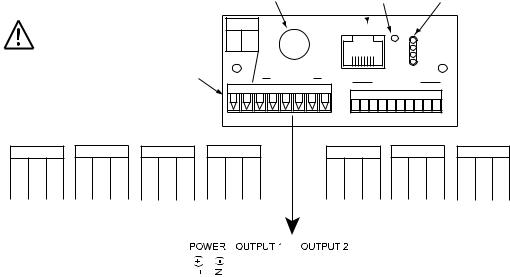
2.1.2 Rear Panel
The rear panel connections are shown in Figure 2.2.
|
|
Use copper conductors |
|
|
LOCATION |
CONNECTION |
BUTTON |
|
INDICATORS |
||||||||||||
|
|
|
|
POWER |
|
ETHERNET |
|
|
|
|
|
||||||||||
|
|
|
|
|
|
|
|
|
|
|
|
|
|
|
|
|
|
|
|
||
|
|
only for power connections |
|
L(+) N(-) |
|
|
8 |
1 |
RST |
ACTIVITY |
|
|
|||||||||
|
|
|
|
|
|
|
|
|
|
8 |
7 |
|
|
NET LINK |
|
|
|||||
|
|
|
|
POWER / OUTPUT |
|
|
|
|
|
|
TX |
|
|
|
|||||||
|
|
|
|
|
|
|
|
|
|
|
|
RX |
|
|
|
||||||
|
|
|
|
|
|
|
|
|
|
|
|
|
|
|
|
|
|
|
|
||
|
|
|
|
|
|
CONNECTOR |
|
8 7 6 OUTPUTS 1 |
|
|
NOT USED |
|
|
|
|
||||||
|
SSR |
RELAY |
PULSE |
ANALOG |
|
|
SSR |
RELAY |
PULSE |
||||||||||||
OUTPUT 1 |
OUTPUT 1 |
OUTPUT 1 |
OUTPUT 1 |
|
OUTPUT 2 |
OUTPUT 2 |
OUTPUT 2 |
||||||||||||||
NO |
|
C |
NO NC C |
PUL |
|
RTN |
CUR V RTN |
|
NO |
|
C |
NO NC |
C |
PUL |
|
RTN |
|||||
6 |
5 |
4 |
6 |
5 |
4 |
6 |
5 |
4 |
6 |
5 |
4 |
|
3 |
2 |
1 |
3 |
2 |
1 |
3 |
2 |
1 |
|
|
|
|
|
|
|
|
|
|
|
|
|
|
|
|
|
|
|
|
|
|
|
|
|
|
|
|
|
|
|
|
|
|
|
|
|
|
|
|
|
|
|
|
|
|
|
|
|
|
|
|
|
|
|
|
|
|
|
|
|
|
|
|
|
|
|
|
|
|
|
|
|
|
|
|
|
|
|
|
|
|
|
|
|
|
|
|
|
|
|
|
|
|
|
|
|
|
|
|
|
|
|
|
|
|
|
|
|
|
|
|
|
|
|
|
|
|
|
|
|
|
|
|
|
|
|
|
|
|
|
|
|
|
|
|
|
|
|
|
|
|
|
|
|
|
|
|
|
|
|
|
|
|
|
|
|
|
|
|
|
|
|
|
|
|
|
|
|
|
|
|
|
|
|
|
|
|
|
|
|
|
8 |
|
7 |
6 |
|
5 |
4 |
3 |
2 |
|
1 |
|
|
|
|
|
|
|
|
|
|
|
|
|
||||
|
|
|
Figure 2.2 Rear Panel Power and Output Connections |
||||||||||||||||||||||||||||||||||||||
|
|
|
|
|
|
|
|
Table 2.2 Rear Panel Connector |
|||||||||||||||||||||||||||||||||
POWER |
AC/DC Power Connector: All models |
|
|
|
|
|
|
|
|
|
|
|
|
|
|
||||||||||||||||||||||||||
OUTPUT 1 |
Based on one of the following models: |
||||||||||||||||||||||||||||||||||||||||
|
|
|
|
|
|
|
Relay SPDT |
|
|
|
|
|
|
|
|
|
|
|
|
|
|
|
|
|
|
|
|
|
|
|
|
|
|||||||||
|
|
|
|
|
|
|
Solid State Relay (SSR) |
|
|
|
|
|
|
|
|
|
|
|
|
|
|
|
|
|
|
|
|
|
|||||||||||||
|
|
|
|
|
|
|
Pulse |
|
|
|
|
|
|
|
|
|
|
|
|
|
|
|
|
|
|
|
|
|
|
|
|
|
|||||||||
|
|
|
|
|
|
|
Analog Output (Voltage and Current) |
|
|
|
|
|
|
|
|
|
|
|
|
|
|
||||||||||||||||||||
OUTPUT 2 |
Based on one of the following models: |
||||||||||||||||||||||||||||||||||||||||
|
|
|
|
|
|
|
Relay SPDT |
|
|
|
|
|
|
|
|
|
|
|
|
|
|
|
|
|
|
|
|
|
|
|
|
|
|||||||||
|
|
|
|
|
|
|
Solid State Relay (SSR) |
|
|
|
|
|
|
|
|
|
|
|
|
|
|
|
|
|
|
|
|
|
|||||||||||||
|
|
|
|
|
|
|
Pulse |
|
|
|
|
|
|
|
|
|
|
|
|
|
|
|
|
|
|
|
|
|
|
|
|
|
|||||||||
Network Communication Interface Section: |
|
|
|
|
|
|
|
|
|
|
|
|
|
|
|
|
|
||||||||||||||||||||||||
ETHERNET |
RJ45 interface for 10BASE-T connection. |
|
|||||||||||||||||||||||||||||||||||||||
RESET |
Button: Used for power reseting the Ethernet board. |
|
|||||||||||||||||||||||||||||||||||||||
ACTIVITY |
LED (Red) Blinking: Indicates network activities (receiving or |
||||||||||||||||||||||||||||||||||||||||
NET LINK |
sending packets). |
|
|
|
|
|
|
|
|
|
|
|
|
|
|
|
|
|
|
|
|
|
|
|
|
|
|||||||||||||||
LED (Green) Solid: Indicates good network link. |
|||||||||||||||||||||||||||||||||||||||||
TX |
LED (Yellow) Blinking: Indicates transmitting data to the serial port. |
||||||||||||||||||||||||||||||||||||||||
RX |
LED (Green) Blinking: Indicates receiving data on the serial port. |
||||||||||||||||||||||||||||||||||||||||
6

2.1.3 Dimensions
|
|
3.780 [96.00] |
|
1 |
1 |
1.890 |
2 |
2 |
%RH |
C |
|
[48.00] |
D |
F |
|
1 |
|
|
2 |
|
|
C |
|
|
F |
|
0.700 [17.78] |
|
|
4.325
[109.85]
PANEL THICKNESS 0.25 (6.4) MAX 0.03 (0.6) MIN
PANEL CUTOUT
1/8 DIN
Figure 2.3 Mounting Dimensions
7
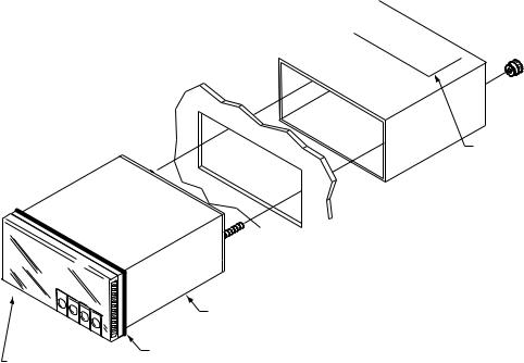
2.1.4 Assembly and Mounting
2.1.4.1 Panel Mounting Instruction
1.Using the dimensions from the panel cutout in Figure 2.3, cut an opening in the panel.
2.Remove sleeve from the rear of the case by removing thumbnuts.
3.Insert the case into the opening from the front of the panel, so the gasket seals between the bezel and the front of the panel.
4.Slip the sleeve over the rear of the case.
5.Tighten the thumbnuts to hold the unit firmly in the panel.


 Thumbnuts
Model No.
 Sleeve Label

 Panel
Panel
|
Case |
Front Bezel |
Gasket |
|
Figure 2.4 Panel Mounting
8

2.1.4.2 Antenna Mounting Instruction
For best reception: connect the antenna directly to the rear of the meter, if the meter is not installed in a metal panel or enclosure.
If the rear of the meter is behind a metal panel or in a cabinet, use a coaxial cable to position the antenna outside of the enclosure in the open air.
Use the shortest cable that can reach a suitable location. The antenna on this Meter and any End Devices should be installed in a vertical position, pointing towards the sky.
Metallic structure should be kept at least 0.8” (2 cm), although 2.4” (6 cm) is recommended away from the antenna.
Any casing that encloses the antenna should be plastic. In addition, it is also wise to avoid plastic case with dark fillers or colorants.
Refer to Section 5 for more Environmental / Operating Conditions.
METER MOUNTED
IN NON-METALIC
ENCLOSURE.
METER MOUNTED
IN A METALIC
ENCLOSURE.
Figure 2.5 Antenna Mounting
9
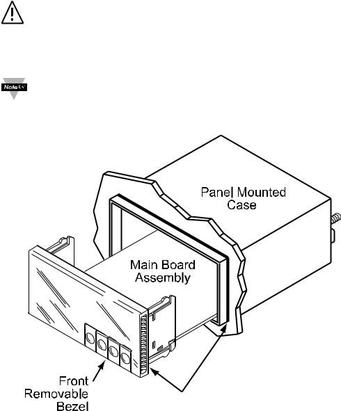
2.1.4.3 Disassembly Instruction
If necessary, the board assembly may be removed from the front of the case housing.
Warning: Disconnect ac power from the unit before proceeding. 1. Remove the board assembly from the case by pulling at the sides of the bezel. 2. The bezel, along with the board assembly will unlatch from the case housing.
• Depending on the size of your Ethernet connector, you may need to disconnect it from the RJ45 jack on the rear of the meter.
• Depending on the length of your antenna cable, you may need to disconnect it from the rear of the meter.
Gasket
Figure 2.6 Accessing the Main Board Assembly
10
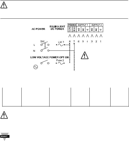
2.1.5 Electrical Installation
2.1.5.1 Power Connections
Warning: Do not connect ac power to your meter until you have completed all output connections. This meter must only be installed by a specially trained electrician with corresponding qualifications. Failure to follow all instructions and warnings may result in injury!
Connect the main power connections as shown below.
90 to 240 Vac 110 to 375 Vdc
|
|
|
|
|
|
|
|
|
|
|
|
|
|
|
|
|
|
|
|
|
|
|
|
|
|
|
|
|
|
|
|
|
|
|
|
|
|
|
|
|
|
|
|
|
|
|
|
|
|
|
|
|
|
|
|
|
|
|
|
|
|
|
|
|
|
|
|
|
|
|
|
|
|
|
|
|
|
|
|
|
|
|
|
|
|
|
|
|
|
|
|
|
|
|
|
|
|
|
|
|
|
|
|
|
|
|
|
|
|
|
|
|
|
|
|
|
|
|
|
|
|
|
|
|
|
|
|
|
|
|
|
|
|
|
|
|
|
|
Use copper |
|
|||||||||||
|
|
|
|
|
|
|
|
|
|
|
|
|
|
|
|
|
|
|
|
|
|
|
|
|
|
||||||||||||
|
OR |
|
|
|
|
|
|
|
|
|
|
|
|
|
|
|
|
|
|
|
|
|
|
|
|||||||||||||
|
|
|
|
|
|
|
|
|
|
|
|
|
|
|
|
|
|
|
|
|
|
|
|
|
conductors only for |
||||||||||||
|
|
|
|
|
|
|
|
|
|
|
|
|
|
|
|
|
|
|
|
|
|
|
|
|
|||||||||||||
|
|
|
|
|
|
|
|
|
|
|
|
|
|
|
|
|
|
|
|
|
|
|
|
|
power connections |
||||||||||||
|
|
|
24 Vac or |
|
|
|
|
|
|
|
|
|
|
|
|
|
|
|
|
|
|
|
|
|
|
|
|
|
|
|
|||||||
|
|
|
20 to 36 Vdc |
|
|
|
|
|
|
|
|
|
|
|
|
|
|
|
|
|
|
|
|
|
|
|
|
|
|
|
|||||||
|
|
|
Figure 2.7 Main Power Connections |
|
|||||||||||||||||||||||||||||||||
Table 2.3 Fuse Requirement (See Specifications Section) |
|
||||||||||||||||||||||||||||||||||||
|
|
|
|
|
|
|
|
|
|
|
|
|
|
|
|
|
|
|
|
|
|
|
|
|
|
|
|
|
|
|
|
|
|
|
|
|
|
FUSE |
Connector |
|
|
|
Output Type |
|
For 115Vac |
|
|
For 230Vac |
DC |
||||||||||||||||||||||||||
|
|
|
|
|
|
|
|
|
|
|
|
|
|
|
|
|
|
|
|
|
|
|
|
|
|
|
|
|
|
|
|
|
|
|
|
|
|
FUSE 1 |
Power |
|
|
|
N/A |
|
100 mA(T) |
|
|
100 mA(T) |
100 mA(T) |
||||||||||||||||||||||||||
FUSE 2 |
Power |
|
|
|
N/A |
|
N/A |
|
|
N/A |
400 mA(T) |
||||||||||||||||||||||||||
For the low voltage power option, in order to maintain the same degree of protection as the standard high voltage input power units (90 - 240 Vac), always use a Safety Agency Approved DC or AC source with the same Overvoltage Category and pollution degree as the standard AC unit (90 - 240 Vac).
The Safety European Standard EN61010-1 for measurement, control, and laboratory equipment requires that fuses must be specified based on IEC127. This standard specifies for a Time-lag fuse, the letter code “T”. The above recommended fuses are of the type IEC127-2-sheet III. Be aware that there are significant differences between the requirements listed in the UL 248-14/CSA 248.14 and the IEC 127 fuse standards. As a result, no single fuse can carry all approval listings. A 1.0 Amp IEC fuse is approximately equivalent to a 1.4 Amp UL/CSA fuse. It is advised to consult the manufacturer’s data sheets for a cross-reference.
11
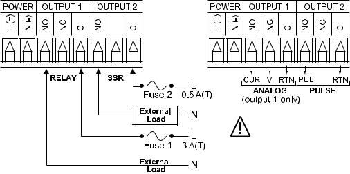
2.1.5.2 Wiring Outputs
This meter has two factory installed outputs. The SPDT Mechanical Relay, SPST Solid State Relay, Pulse and Analog Output Connection are shown below.
Use copper conductors only for power connections
|
|
|
|
|
|
|
|
|
|
|
|
Figure 2.8 |
|
||
a) Mechanical Relay and SSR |
b) Pulse and Analog |
||
Outputs Wiring Hookup |
Outputs Wiring Hookup |
||
12
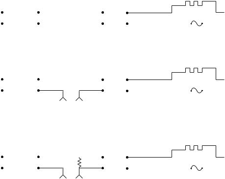
2.1.5.2 Wiring Outputs (continued)
dc CONTROLLED SSR USED WITH TEMPERATURE CONTROLLER WITH dc VOLTAGE SSR DRIVER OUTPUT
|
|
|
|
|
|
|
|
|
|
|
|
|
|
|
|
|
|
||
|
|
TEMPERATURE |
CONTROL |
|
dc INPUT |
|
|
LOAD |
|
|
|
|
|
||||||
|
|
|
CONTROLLER |
|
|
SSR |
|
|
|
|
|
HEATER |
|
|
|||||
|
|
|
|
|
SIDE |
|
4 |
|
1 |
|
|
|
SIDE |
|
|
||||
Vac |
|
|
|
|
|
|
|
|
|
|
|
|
|
|
|
|
Vac |
||
|
|
|
|
|
|
|
|
|
|
|
|
|
|
|
|
||||
|
|
|
|
|
|
|
3 |
|
2 |
|
|
|
|
|
|
|
|
|
|
|
|
|
|
|
0 or 5 Vdc, |
|
|
|
|
|
|
FAST BLOW |
|
|
|||||
|
|
|
|
|
|
|
|
|
|
|
|
|
|
|
|
||||
|
|
|
|
|
TYPICALLY |
|
|
|
|
|
|
|
|
|
|
||||
|
|
|
|
|
|
|
|
|
|
|
|
|
FUSE |
|
|
||||
|
|
|
|
|
|
|
|
|
|
|
|
|
|
|
|
|
|||
ac CONTROLLED SSR USED WITH TEMPERATURE CONTROLLER WITH MECHANICAL RELAY OUTPUT |
|
|
|||||||||||||||||
|
|
|
|
|
|
|
|
|
|
|
|
|
|
|
|
|
|
||
|
|
TEMPERATURE |
CONTROL |
|
ac INPUT |
|
|
LOAD |
|
|
|
|
|
||||||
|
|
|
CONTROLLER |
|
|
|
|
|
|
|
|
||||||||
|
|
|
|
|
SSR |
|
|
|
|
|
|
|
|
|
|
||||
|
|
|
|
|
SIDE |
|
4 |
1 |
|
|
|
SIDE |
HEATER |
|
|
||||
|
|
|
|
|
|
|
|
|
|
|
|
||||||||
Vac |
|
|
|
|
|
|
|
|
|
|
|
|
|
|
|
|
Vac |
||
|
|
|
|
|
|
|
|
|
|
|
|
|
|
|
|
||||
|
|
|
|
|
|
|
3 |
|
2 |
|
|
|
|
|
|
|
|
|
|
|
|
|
|
|
|
|
|
|
|
|
|
FAST BLOW |
|
|
|||||
|
|
|
|
|
|
|
|
|
|
|
|
|
|
|
|
|
|||
|
|
|
|
|
|
|
|
|
|
|
|
|
|
|
|
|
|||
|
|
|
|
|
Vac |
|
|
|
|
|
|
|
|
FUSE |
|
|
|||
|
|
|
|
|
DRIVING |
|
|
|
|
|
|
|
|
|
|
|
|
|
|
|
|
|
|
|
SSR |
|
|
|
|
|
|
|
|
|
|
|
|
|
|
|
|
ac CONTROLLED SSR USED WITH TEMPERATURE CONTROLLER WITH TRIAC OUTPUT |
|
|
|||||||||||||||
|
|
|
|
|
|
|
|
|
|
|
|
|
|||||||
|
|
TEMPERATURE |
CONTROL SIDE |
|
ac INPUT |
|
|
LOAD |
|
|
|
|
|
||||||
|
|
|
CONTROLLER |
LOAD |
|
|
SSR |
|
|
|
|
|
HEATER |
|
|
||||
|
|
|
|
|
RESISTOR |
|
4 |
|
1 |
|
|
|
SIDE |
|
|
||||
Vac |
|
|
|
|
|
|
|
|
|
|
|
|
|
|
|
|
Vac |
||
|
|
|
|
|
|
|
|
|
|
|
|
|
|
|
|
||||
|
|
|
|
|
|
|
3 |
|
2 |
|
|
|
|
|
|
|
|
|
|
|
|
|
|
|
|
|
|
|
|
|
|
FAST BLOW |
|
|
|||||
|
|
|
|
|
|
|
|
|
|
|
|
|
|
|
|
|
|||
|
|
|
|
|
|
|
|
|
|
|
|
|
|
|
|
|
|||
|
|
|
|
|
Vac |
|
|
|
|
|
|
|
|
FUSE |
|
|
|||
|
|
|
|
|
DRIVING |
|
|
|
|
|
|
|
|
|
|
|
|
|
|
|
|
|
|
|
SSR |
|
|
|
|
|
|
|
|
|
|
|
|
|
|
|
|
|
|
|
Figure 2.9 Typical Applications |
|
|
|
|
|
|||||||||
13
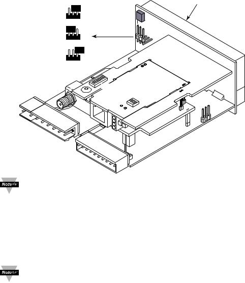
2.1.5.3 Jumper Settings for Display Color Setup |
||||||
To change the color of the lower display follow the instructions below: |
||||||
1. |
The unit should be removed from the panel and opened. |
|||||
|
Refer to Section 2.1.4.3 for assembly and disassembly instructions. |
|||||
2. |
Locate S1 jumper, on the back side of the display board. Select the |
|||||
|
position for your color choice of Red, Green or Amber. |
|||||
|
|
|
|
|
|
Display Board |
|
RED |
S1 |
|
|
|
S1 |
|
|
|
GREEN |
|
||
|
GREEN |
S1 |
|
RED |
||
|
|
|
|
|||
|
|
|
|
|
||
|
AMBER |
S1 (Open) |
|
|
|
|
|
|
|
1 |
|
|
|
|
|
8 |
ON |
|
|
|
|
|
|
ON |
4 |
3 |
2 |
|
|
|
|
|
1 |
|
|
|
|
|
|
|
|
Figure 2.10 Location of S1 Jumper
To change the color of the upper Display, see Section 4.3.7.5.
2.1.5.4 Dip Switches
To change the DIP switches, follow the instructions below:
1. The unit should be removed from the panel and opened.
Refer to Section 2.1.4.3 for assembly and disassembly instructions. 2. Locate the 4 and 8 position DIP switches, on the top board.
The Meter is shipped with all DIP switches in "OFF" position
To set the Wireless and Ethernet settings to Factory Default, Refer to
Section 7.
14
2.1.5.4 Dip Switches (continued) |
|
|
1 |
To change the |
|
|
Wireless settings to |
|
2-5 |
Factory Default |
|
OFF positions |
S1 |
|
6-8 |
Network1ID (NID) |
|
8
OFF ON 

8 Position
DIP Switch on Wireless Board
Figure 2.11
OFF |
1 |
8 |
ON |
ON |
4 |
3 2 OFF |
|
1 |
|
|
|
 4 Position
DIP Switch on
Ethernet Board
Location of DIP Switches
4 |
3 2 |
1 |
|
|
|
|
|
OFF |
ON |
1 |
N/A |
|
2 |
To change the |
|
|
Ethernet settings |
|
3 |
to Factory Default |
|
To enable/disable |
|
|
4 |
DHCP |
|
N/A |
|
|
|
|
|
|
|
|
|
Definitions: |
|
|
|
PID |
NID |
#6 |
#7 |
#8 |
|
|
|
|
|
|
NID (Network ID): The last 3 DIP |
|||||
|
|
13106 (0x3332) |
0 |
OFF |
OFF |
OFF |
|
||
|
|
switches used to assign a unique |
|||||||
|
|
13107 (0x3333) |
1 |
ON |
OFF |
OFF |
|
||
|
|
network number to a network of a |
|||||||
|
|
13108 (0x3334) |
2 |
OFF |
ON |
OFF |
Meter and End Device(s). |
||
|
|
PID (Personal Network ID): The |
|||||||
|
|
13109 (0x3335) |
3 |
ON |
ON |
OFF |
|
||
|
|
|
sum of the Network ID (NID) and |
||||||
|
|
|
|
|
|
|
|||
|
|
13110 (0x3336) |
4 |
OFF |
OFF |
ON |
|
13106 (0x3332). The PID as |
|
|
|
13111 (0x3337) |
5 |
ON |
OFF |
ON |
defined by IEEE for 802.15.4 |
||
|
|
standard is an identifying factor for |
|||||||
|
|
|
|
|
|
|
|
|
|
|
|
13112 (0x3338) |
6 |
OFF |
ON |
ON |
|
separating 802.15.4 wireless |
|
|
|
13113 (0x3339) |
7 |
ON |
ON |
ON |
networks to avoid overlapping and |
||
|
|
allow interoperability. |
|||||||
|
|
|
|
|
|
|
|
|
|
|
|
|
Once the End Devices and the Meter start communicating, make sure to leave DIP |
||||||
|
|
|
switch #1 on the Wireless Board of the Meter, to the OFF position. This will lock the |
||||||
|
|
|
|||||||
|
|
|
Meter on the same channel it initially established the connection. |
||||||
|
|
|
It’s a good practice to record NID numbers on designated label placed on the |
||||||
|
|
|
Meter (see Figure 3.1). |
|
|
|
|
||
|
|
|
|
|
|
|
|||
15
2.2 Network Communication Interfaces |
|
|
|
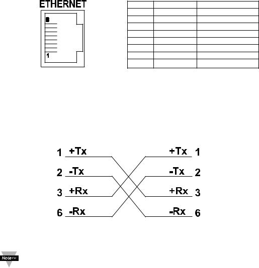
2.2.1 10Base-T RJ-45 Pinout |
|
|
|
The 10BASE-T Ethernet network (RJ-45) system is used in the Meter for |
|||
network connectivity. The 10 Mbps twisted-pair Ethernet system operates over |
|||
two pairs of wires. One pair is used for receiving data signals and the other pair |
|||
is used for transmitting data signals. This means that four pins of the eight-pin |
|||
connector are used. |
|
|
|
|
Pin |
Name |
Description |
|
1 |
+Tx |
+ Transmit Data |
|
2 |
-Tx |
- Transmit Data |
|
3 |
+RX |
+ Receive Data |
|
4 |
N/C |
Not Connected |
|
5 |
N/C |
Not Connected |
|
6 |
-Rx |
- Receive Data |
|
7 |
N/C |
Not Connected |
|
8 |
N/C |
Not Connected |
|
Figure 2.12 RJ45 Pinout |
|
|
2.2.2 10Base-T Crossover Wiring
When connecting the iServer directly to the computer, the transmit data pins of the computer should be wired to the receive data pins of the Meter, and vice versa. The 10Base-T crossover cable with pin connection assignments are shown below.
Figure 2.13 10Base-T Crossover Cable Wiring
Use straight through cable for connecting the Meter to an Ethernet hub. The ports on the hub are already crossed.
16
PART 3
NETWORK CONFIGURATION
3.1 Ethernet (MAC) Address
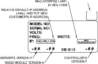
MAC (Media Access Control) address is your computer's unique hardware number. When you're connected to the LAN from your computer, a correspondence table relates your IP address to your computer's physical (MAC) address. The MAC address can be found on the label of your meter (see Figure 2.4 and 3.1) and contains 6 bytes (12 characters) of hexadecimal numbers XX:XX:XX:XX:XX:XX For Example: 0A:0C:3D:0B:0A:0B
Remove the small label with the default IP address and there will be room to put your IP address.
There is also a small label for your Network ID address (NID).
NET.ADDR
3.2 Network Protocols Figure 3.1 Label Detail
The Meter can be connected to the network using standard TCP/IP protocols. It also supports ARP, HTTP (Web Server), DHCP, DNS and Telnet protocols.
3.3 DHCP
DHCP, Dynamic Host Configuration Protocol enables computers and devices to extract their IP configurations from a server (DHCP server).
If the DHCP is enabled on your Meter, as soon as the Meter is connected to the network, there is an exchange of information between DHCP server and the Meter. During this process the IP address, the Gateway address, and the Subnet Mask will be assigned to the Meter by the DHCP server. Note that the DHCP server must be configured correctly to do such assignment.
17

3.3 DHCP (continued)
The Meter is shipped with DHCP disabled (factory default).
If fixed or static IP address is desired, the DHCP must be disabled.
The DHCP can be enabled by setting the DIP switch # 3 to the “ON” position
Figure 3.2 4 Position DIP Switch
Setting the Meter’s IP address to 0.0.0.0 will also enable DHCP.
3.4 DNS
DNS, Domain Name System enables computers and devices to be recognized over a network based on a specific name instead of IP addresses.
For example, instead of having to use http://192.168.1.200 (IP address), you would use only http://wis03ec or any eight character name stored as Host Name under “Access Control” page from the Wireless System Home Page. The default DNS name for the Meter is "wis" followed by the last four digits of the MAC address of that particular Meter.
1. It is very important to communicate with the network administrator in order to understand DHCP and its existing configurations on the
host server, before enabling DHCP on the Meter.
2. The Meters are shipped with a default static IP address of
192.168.1.200 and Subnet Mask of 255.255.255.0.
3. On Windows servers where DCHP and DNS are separate functions it is very important to configure the DHCP server to communicate with DNS in order for the iServer’s Host Name to correctly respond. If you cannot access the iServer using its Host Name, please contact your network administrator to make sure the DHCP and DNS servers are linked together.
18

3.5 IP Address
Every active device connected to the TCP/IP network must have a unique IP address. This IP address is used to establish a connection to the Meter. Every computer using TCP/IP should have a unique 32-bit address which is divided into two portions, the network ID and the host ID. For instance, every computer on the same network uses the same network ID. At the same time, all of them have a different host ID. For more details about the IP address see Appendix B.
3.5.1 Default IP Address
The Meter is shipped with a default IP address of 192.168.1.200 and Subnet Mask of 255.255.255.0. If you are going to use a Web browser or Telnet program to access the Meter using its default IP address, make sure that the PC from which you’re establishing the connection has an IP address that is in the same range as the Meter’s IP address (192.168.1.x, where x can be any number from 1 to 254). See Section 3.5.2.
Your PC’s IP address cannot be the same as the Meter’s IP address.
You also need to make sure that your PC’s Subnet Mask is 255.255.255.0. This is a good way to access the Meter over the network and make any configuration changes needed. If 192.168.1.200 is already in use on your network, use an Ethernet crossover cable between your computer and the Meter to change the IP address or any other settings within the Meter.
19

3.5.2 Changing TCP/IP Properties on Your Computer
Go to your computer’s Control Panel then Network Connections. Pick the network with the proper Ethernet card. Right click and choose
Properties
Look for Internet Protocol, click on it and press Properties
|
Figure 3.3 Network Connections |
|||||
Setup the IP address (in this case, 192.168.1.1) as shown below and press OK |
||||||
|
|
|
|
You can access the Meter’s Web |
||
|
|
|
|
Server via any internet browser |
||
|
|
|
|
using IP address of 192.168.1.200. |
||
|
|
|
|
Once you log into the Meter’s Web |
||
|
|
|
|
Server, you will be able to change its |
||
|
|
|
|
IP configuration according to |
||
|
|
|
|
Section 4.2. |
||
|
|
|
|
|
|
After you configure the |
|
|
|
|
|
|
|
|
|
|
|
|
|
|
|
|
|
|
|
|
Meter’s IP configurations, |
|
|
|
|
|
|
you should go back and set |
|
|
|
|
|
|
your PC’s previous IP |
|
|
|
|
|
|
settings. |
. |
|
|
|
|
|
|
|
Figure 3.4 Network Connections |
|||||
20
PART 4
NETWORK OPERATIONS
This Meter can be used and configured in several ways, depending on user’s preference and network setup. It can be configured using a Web browser, like Internet Explorer. It can also be configured using the iConnect Configuration Software.
If DHCP and DNS servers are configured to exchange information, the connection will be very simple. All you need to do is to enable DHCP on the Meter (see Section 3.3) and use a straight through network cable to connect the Meter to an Ethernet hub or switch and power it up. Now, you can use the Meter’s default Host (Domain) Name, which is wisxxxx (where xxxx are the last four characters of its MAC address) to access the Meter’s Web Server.
If DHCP is not the preferred method, you can configure your PC’s network connection with an IP address of 192.168.1.x that is in the same range as the Meter’s default IP address (192.168.1.200) and connect to the Meter using a cross-over network cable between your PC’s network port and the Meter. After you’re done with configuring the Meter, you can always set your PC back to its original settings. See Section 3.5.2 for more details.
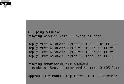
On your computer, from the MS-DOS Prompt window type "ping 192.168.1.200” and press Enter. If DHCP and DNS servers are used type “ping wisxxxx”, where xxxx are the last four digits of the Meter’s MAC address, located on the meter. You should get a reply as shown in Figure 4.1.
You can use the host name (wisxxxx) instead of the IP address only if your DHCP server is configured to communicate with your DNS. Please consult with your IT department for details.
4.0 Testing the Connection
Figure 


 Prompt
This proves that the connection is proper and you can get into configuration or run mode using the Telnet or Web browser.
21

4.1 iConnect Software
The Meter may also be assigned an IP Address by using the iConnect software. a) Download the iConnect software from the website listed in this manual.
b) Install iConnect software on a networked PC. This software is compatible with Windows 95, 98, NT, 2000, and XP.
c) Use iConnect to assign an IP address to the Meter and access its web pages for configuration. You can also use any standard web browser to access the Wireless System’ web pages. Consult with your IT department for obtaining an IP address.
|
|
|
|
|
|
|
|
|
|
|
|
|
|
|
|
|
|
|
|
|
|
|
|
|
|
|
|
|
|
|
|
|
|
|
|
|
|
|
|
|
|
|
|
|
|
|
|
|
|
|
|
|
|
|
|
|
|
|
|
|
|
|
|
|
|
|
|
|
|
|
|
|
|
|
|
|
|
|
|
|
|
|
|
|
|
|
|
|
|
|
|
|
|
|
|
|
|
|
|
|
|
|
|
|
|
|
|
|
|
|
|
|
|
|
|
|
|
|
|
|
|
|
|
|
|
|
|
|
|
|
|
|
|
|
|
|
|
|
|
|
|
|
|
|
|
|
|
|
|
|
|
|
|
|
|
|
|
|
|
|
|
|
|
|
|
|
|
|
|
|
|
|
|
|
|
|
|
|
|
|
|
|
|
|
|
|
|
|
|
|
|
|
|
|
|
|
|
|
|
|
|
|
|
|
|
|
|
|
|
|
|
|
|
|
|
|
|
|
|
|
|
|
|
|
|
|
|
|
|
|
|
|
|
|
|
|
|
|
|
|
|
|
|
|
|
|
|
|
|
|
|
|
|
|
|
|
|
|
|
|
|
|
|
|
|
|
|
|
|
|
|
|
|
|
|
|
|
|
|
|
|
|
|
|
|
|
|
|
|
|
|
|
|
|
|
|
|
|
|
|
|
|
|
|
|
|
|
|
|
|
|
|
|
|
|
|
|
|
|
|
|
|
|
|
|
|
|
|
|
|
|
|
|
|
|
|
|
|
|
|
|
|
|
|
|
|
|
|
|
|
|
|
|
|
|
|
|
|
|
|
|
|
|
|
|
|
|
|
|
|
|
|
|
|
|
|
|
|
|
|
|
|
|
|
|
|
|
|
|
|
|
|
|
|
|
|
|
|
|
|
|
|
|
|
|
|
|
|
|
|
|
|
|
|
|
|
|
|
|
|
|
|
|
|
|
|
|
|
|
|
|
|
|
|
|
|
|
|
|
|
|
|
|
|
|
|
|
|
|
|
|
|
|
|
|
|
|
|
|
|
|
|
|
|
|
|
|
|
|
|
|
|
|
|
|
|
|
|
|
|
|
|
|
|
|
|
|
|
|
|
|
|
|
|
|
|
|
|
|
|
|
|
|
|
|
|
|
|
|
|
|
|
|
|
|
|
|
|
|
|
|
|
|
|
|
|
|
|
|
|
|
|
|
|
|
|
|
|
|
|
|
|
|
|
|
|
|
|
|
|
|
|
|
|
|
|
|
|
|
|
|
|
|
|
|
|
|
|
|
|
|
|
|
|
|
|
|
|
|
|
|
|
|
|
|
|
|
|
|
|
|
|
|
|
|
|
|
|
|
|
|
|
|
|
|
|
|
|
|
|
|
|
|
|
|
|
|
|
|
|
|
|
|
|
|
|
|
|
|
|
|
|
|
|
|
|
|
|
|
|
|
|
|
|
|
|
|
|
|
|
|
|
|
|
|
|
|
|
|
|
|
|
|
|
|
|
|
|
|
|
|
|
|
|
|
|
|
|
|
|
|
|
|
|
|
|
|
|
|
|
|
|
|
|
|
|
|
|
|
|
|
|
|
|
|
|
|
|
|
|
|
|
|
|
|
|
|
|
|
|
|
|
|
|
|
|
|
|
|
|
|
|
|
|
|
|
|
|
|
|
|
|
|
|
|
|
|
|
|
|
|
|
|
|
|
|
|
|
|
|
|
|
|
|
|
|
|
|
|
|
|
|
|
|
|
|
|
|
|
|
|
|
|
|
|
|
|
|
|
|
|
|
|
|
|
|
|
|
|
|
|
|
|
|
|
|
|
|
|
|
|
|
|
|
|
|
|
|
|
|
|
|
|
|
|
|
|
|
|
|
|
|
|
|
|
|
|
|
|
|
|
|
|
|
|
|
|
|
|
|
|
|
|
|
|
|
|
|
|
|
|
|
|
|
|
|
|
|
|
|
|
|
|
|
|
|
|
|
|
|
|
|
|
|
|
|
|
|
|
|
|
|
|
|
|
|
|
|
|
|
|
|
|
|
|
|
|
|
|
|
|
|
|
|
|
|
|
|
|
|
|
|
|
|
|
|
|
|
|
|
|
|
|
|
|
|
|
|
|
|
|
|
|
|
|
|
|
|
|
|
|
|
|
|
|
|
|
|
|
|
|
|
|
|
|
|
|
|
|
|
|
|
|
|
|
|
|
|
|
|
|
|
|
|
|
|
|
|
|
|
|
|
|
|
|
|
|
|
|
|
|
|
|
|
|
|
|
|
|
|
|
|
|
|
|
|
|
|
|
|
|
|
|
|
|
|
|
|
|
|
|
|
|
|
|
|
|
|
|
|
|
|
|
|
|
|
|
|
|
|
|
|
|
|
|
|
|
|
|
|
|
|
|
|
|
|
|
|
|
|
|
|
|
|
|
|
|
|
|
|
|
|
|
|
|
|
|
|
|
|
|
|
|
|
|
|
|
|
|
|
|
|
|
|
|
|
|
|
|
|
|
|
|
|
|
|
|
|
|
|
|
|
|
|
|
|
|
|
|
|
|
|
|
|
|
|
|
|
|
|
|
|
|
|
|
|
|
|
|
|
|
|
|
|
|
|
|
|
|
|
|
|
|
|
|
|
|
|
|
|
|
|
|
|
|
|
|
|
|
|
|
|
|
|
|
|
|
|
|
|
|
|
|
|
|
|
|
|
|
|
|
|
|
|
|
|
|
|
|
|
|
|
|
|
|
|
|
|
|
|
|
|
|
|
|
|
|
|
|
|
|
|
|
|
|
|
|
|
|
|
|
|
|
|
|
|
|
|
|
|
|
|
|
|
|
|
|
|
|
|
|
|
|
|
|
|
|
|
|
|
|
|
|
|
|
|
|
|
|
|
|
|
|
|
|
|
|
|
|
|
|
|
|
|
|
|
|
|
|
|
|
|
|
|
|
|
|
|
|
|
|
|
|
|
|
|
|
|
|
|
|
|
|
|
|
|
|
|
|
|
|
|
|
|
|
|
|
|
|
|
|
|
|
|
|
|
|
|
|
|
|
|
|
|
|
|
|
|
|
|
|
|
|
|
|
|
|
|
|
|
|
|
|
|
|
|
|
|
|
|
|
|
|
|
|
|
|
|
|
|
|
|
|
|
|
|
|
|
|
|
|
|
|
|
|
|
|
|
|
|
|
|
|
|
|
|
|
|
|
|
|
|
|
|
|
|
|
|
|
|
|
|
|
|
|
|
|
|
|
|
|
|
|
|
|
|
|
|
|
|
|
|
|
|
|
|
|
|
|
|
|
|
|
|
|
|
|
|
|
|
|
|
|
|
|
|
|
|
|
|
|
|
|
|
|
|
|
|
|
|
|
|
|
|
|
|
|
|
|
|
|
|
|
|
|
|
|
|
|
|
|
|
|
|
|
|
|
|
|
|
|
|
|
|
|
|
|
|
|
|
|
|
|
|
|
|
|
|
|
|
|
|
|
|
|
|
|
|
|
|
|
|
|
|
|
|
|
|
|
|
|
|
|
|
|
|
|
|
|
|
|
|
|
|
|
|
|
|
|
|
|
|
|
|
|
|
|
|
|
|
|
|
|
|
|
|
|
|
|
|
|
|
|
|
|
|
|
|
|
|
|
|
|
|
|
|
|
|
|
|
|
|
|
|
|
|
|
|
|
|
|
|
|
|
|
|
|
|
|
|
|
|
|
|
|
|
|
|
|
|
|
|
|
|
|
|
|
|
|
|
|
|
|
|
|
|
|
|
|
|
|
|
|
|
|
|
|
|
|
|
|
|
|
|
|
|
|
|
|
|
|
|
|
|
|
|
|
|
|
|
|
|
|
|
|
|
|
|
|
|
|
|
|
|
|
|
|
|
|
|
|
|
|
|
|
|
|
|
|
|
|
|
|
|
|
|
|
|
|
|
|
|
|
|
|
|
|
|
|
|
|
|
|
|
|
|
|
|
|
|
|
|
|
|
|
|
|
|
|
|
|
|
|
|
|
|
|
|
|
|
|
|
|
|
|
|
|
|
|
|
|
|
|
|
|
|
|
|
|
|
|
|
|
|
|
|
|
|
|
|
|
|
|
|
|
|
|
|
|
|
|
|
|
|
|
|
|
|
|
|
|
|
|
|
|
|
|
|
|
|
|
|
|
|
|
|
|
|
|
|
|
|
|
|
|
|
|
|
|
|
|
|
|
|
|
|
|
|
|
|
|
|
|
|
|
|
|
|
|
|
|
|
|
|
|
|
|
|
|
|
|
|
|
|
|
|
|
|
|
|
|
|
|
|
|
|
|
|
|
|
|
|
|
|
|
|
|
|
|
|
|
|
|
|
|
|
|
|
|
|
|
|
|
|
|
|
|
|
|
|
|
|
|
|
|
|
|
|
|
|
|
|
|
|
|
|
|
|
|
|
|
|
|
|
|
|
|
|
|
|
|
|
|
|
|
|
|
|
|
|
|
|
|
|
|
|
|
|
|
|
|
|
|
|
|
|
|
|
|
|
|
|
|
|
|
|
|
|
|
|
|
|
|
|
|
|
|
|
|
|
|
|
|
|
|
|
|
|
|
|
|
|
|
|
|
|
|
|
|
|
|
|
|
|
|
|
|
|
|
|
|
|
|
|
|
|
|
|
|
|
|
|
|
|
|
|
|
|
|
|
|
|
|
|
|
|
|
|
|
|
|
|
|
|
|
|
|
|
|
|
|
|
|
|
|
|
|
|
|
|
|
|
|
|
|
|
|
|
|
|
|
|
|
|
|
|
|
|
|
|
|
|
|
|
|
|
|
|
|
|
|
|
|
|
|
|
|
|
|
|
|
|
|
|
|
|
|
|
|
|
|
|
|
|
|
|
|
|
|
|
|
|
|
|
|
|
|
|
|
|
|
|
|
|
|
|
|
|
|
|
|
|
|
|
|
|
|
|
|
|
|
|
|
|
|
|
|
|
|
|
|
|
|
|
|
|
|
|
|
|
|
|
|
|
|
|
|
|
|
|
|
|
|
|
|
|
|
|
|
|
|
|
|
|
|
|
|
|
|
|
|
|
|
|
|
|
|
|
|
|
|
|
|
|
|
|
|
|
|
|
|
|
|
|
|
|
|
|
|
|
|
|
|
|
|
|
|
|
|
|
|
|
|
|
|
|
|
|
|
|
|
|
|
|
|
|
|
|
|
|
|
|
|
|
|
|
|
Figure 4.2 Assigning an IP Address using iConnect |
|||||||||||||||||||||||||||||||||||||||||
1) |
Place the IP address in this box. |
|
|
|
|
|
|
|
|
|
|
|
|
|
|
|
|
|
|
|
|
|
|
|
|
|
|
|||||||||||||||||||
2) |
Take the MAC address from the label attached to the bottom of the Meter |
|||||||||||||||||||||||||||||||||||||||||||||
|
and place it in this box. |
|
|
|
|
|
|
|
|
|
|
|
|
|
|
|
|
|
|
|
|
|
|
|
|
|
|
|||||||||||||||||||
3) |
Click here to send the above IP address to the Meter. |
|||||||||||||||||||||||||||||||||||||||||||||
4) |
After the IP address is assigned to the Meter, click here to access it’s web |
|||||||||||||||||||||||||||||||||||||||||||||
|
pages. |
|
|
|
|
|
|
|
|
|
|
|
|
|
|
|
|
|
|
|
|
|
|
|
|
|
|
|||||||||||||||||||
5) |
Click here to Ping the Meter whose IP address is shown in the IP address box. |
|||||||||||||||||||||||||||||||||||||||||||||
6) |
Click here to find all the Meters on your network . |
|||||||||||||||||||||||||||||||||||||||||||||
7) |
The IP addresses for the Meters found by the iConnect will be listed here. |
|||||||||||||||||||||||||||||||||||||||||||||
8) |
These fields indicate the IP address and the subnet mask of the PC on |
|||||||||||||||||||||||||||||||||||||||||||||
|
which the iConnect is running. |
22 |
|
|
|
|
|
|
|
|
|
|
|
|
|
|
|
|
|
|
|
|
|
|
|
|||||||||||||||||||||
|
|
|
|
|
|
|
|
|
|
|
|
|
|
|
|
|
|
|
|
|
|
|
|
|
|
|
|
|
|
|
|
|
|
|
|
|
|
|
|
|
|
|
|
|||
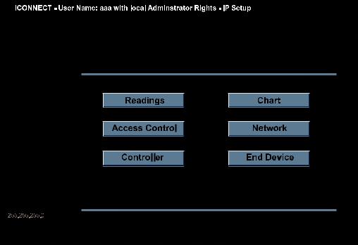
4.1 iConnect Software (continued)
d) To access the Wireless System for Configuration:
Click on the “View Webpage” button, you will access the Wireless System’s home page, refer to Section 4.3 for details.
WIRELESS SENSOR HOME PAGE
Figure 4.3 Accessing the Wireless System for Configuration
23
 Loading...