


Installation and Maintenance Instructions for OMEGA® PX5200 Differrential Pressure Transmitter M-5109/0112
LOOK FOR THIS
AGENCY MARK ON
OUR PRODUCTS


 User’sGuide
Shop online at
omega.comTM


 ®
®
omega.com e-mail: info@omega.com For latest product manuals: omegamanual.info
Version 6.03 5/11
PX5200
M5109/0212

omega.comTM
|
|
® |
|
|
|
|
|
|
|
|
OMEGAnet® Online Service |
|
Internet e-mail |
|
|
|
omega.com |
|
info@omega.com |
|
|
|
|
|
|
|
Servicing North America: |
||
U.S.A.: |
Omega Engineering, Inc., One Omega Drive, P.O. Box 4047 |
|||
ISO 9001 Certified |
Stamford, CT 06907-0047 |
|
||
|
|
Toll-Free: 1-800-826-6342 |
Tel: (203) 359-1660 |
|
|
|
FAX: (203) 359-7700 |
e-mail: info@omega.com |
|
Canada: |
976 Bergar |
|
||
|
|
Laval (Quebec), Canada H7L 5A1 |
|
|
|
|
Toll-Free: 1-800-826-6342 |
TEL: (514) 856-6928 |
|
|
|
FAX: (514) 856-6886 |
e-mail: info@omega.ca |
|
For immediate technical or application assistance:
U.S.A. and Canada: Sales Service: 1-800-826-6342/1-800-TC-OMEGA®
Customer Service: 1-800-622-2378/1-800-622-BEST®
Engineering Service: 1-800-872-9436/1-800-USA-WHEN®
Mexico: |
En Español: 001 (203) 359-7803 |
FAX: (001) 203-359-7807 |
|
info@omega.com.mx |
e-mail: espanol@omega.com |
Servicing Europe:
Benelux: |
Managed by the United Kingdom Office |
|
|
Toll-Free: 0800 099 3344 |
TEL: +31 20 347 21 21 |
|
FAX: +31 20 643 46 43 |
e-mail: sales@omega.nl |
Czech Republic: |
Frystatska 184 |
|
|
733 01 Karviná, Czech Republic |
|
|
Toll-Free: 0800-1-66342 |
TEL: +420-59-6311899 |
|
FAX: +420-59-6311114 |
e-mail: info@omegashop.cz |
France: |
Managed by the United Kingdom Office |
|
|
Toll-Free: 0800 466 342 |
TEL: +33 (0) 161 37 29 00 |
|
FAX: +33 (0) 130 57 54 27 |
e-mail: sales@omega.fr |
Germany/Austria: |
Daimlerstrasse 26 |
|
|
D-75392 Deckenpfronn, Germany |
|
|
Toll-Free: 0 800 6397678 |
TEL: +49 (0) 7059 9398-0 |
|
FAX: +49 (0) 7056 9398-29 |
e-mail: info@omega.de |
United Kingdom: |
OMEGA Engineering Ltd. |
|
ISO 9001 Certified |
One Omega Drive, River Bend Technology Centre, Northbank |
|
|
Irlam, Manchester M44 5BD England |
|
|
Toll-Free: 0800-488-488 |
TEL: +44 (0)161 777-6611 |
|
FAX: +44 (0)161 777-6622 |
e-mail: sales@omega.co.uk |
It is the policy of OMEGA Engineering, Inc. to comply with all worldwide safety and EMC/EMI regulations that apply. OMEGA is constantly pursuing certification of its products to the European New Approach Directives. OMEGA will add the CE mark to every appropriate device upon certification.
The information contained in this document is believed to be correct, but OMEGA accepts no liability for any errors it contains, and reserves the right to alter specifications without notice.
WARNING: These products are not designed for use in, and should not be used for, human applications.
2

|
|
CONTENTS |
|
|
CAUTION ................................................................................................ |
4-5 |
|
1. |
PREFACE .............................................................................................. |
5 |
|
2. |
OVERVIEW .......................................................................................... |
5 |
|
3. |
FEATURES ............................................................................................ |
5 |
|
4. |
SPECIFICATIONS .................................................................................. |
6 |
|
5. |
MOUNTING .......................................................................................... |
8 |
|
|
5.1 Mounting Location ........................................................................ |
8 |
|
|
5.2 Mounting Options ........................................................................ |
8 |
|
|
5.3 Pressure Connection.................................................................... |
8 |
|
6. |
PIPING ................................................................................................ |
9 |
|
7. |
WIRING................................................................................................ |
10 |
|
|
7.1 Cable / Wiring Specifications........................................................ |
10 |
|
|
7.2 Wiring Instructions........................................................................ |
10 |
|
8. |
DISPLAY FUNCTIONS ............................................................................ |
13 |
|
9. |
MODE CHANGES .................................................................................. |
14 |
|
10. |
POWER-ON MESSAGE .......................................................................... |
14 |
|
11. |
MEASUREMENT MODE .......................................................................... |
15 |
|
|
11.1 |
Filter (Damping) .......................................................................... |
15 |
|
11.2 |
Pressure Display Mode (Re-scaling in “inH2O” units) .................. |
15 |
|
11.3 |
Linear Display Mode |
|
|
|
(Re-scaling in arbitrary user defined units) .................................. |
16 |
|
11.4 |
Flow Measurement/Square Root Extraction Mode ...................... |
19 |
|
11.5 |
Min/Max Display .......................................................................... |
26 |
12. |
ZERO ADJUSTMENT MODE .................................................................... |
27 |
|
13. |
KEY LOCK ............................................................................................ |
28 |
|
14. |
SETTING MODE .................................................................................... |
20 |
|
|
14.1 |
Setting Items for Pressure Display Mode |
|
|
|
(Re-scaling in “inH2O” units) ........................................................ |
28 |
|
14.2 |
Setting Items for Linear Display Mode |
|
|
|
(Re-scaling in arbitrary user defined units) .................................. |
29 |
|
14.3 |
Setting Items for Square Root Extraction (Flow Measurement) .. |
31 |
|
14.4 |
Setting Procedure ........................................................................ |
32 |
|
14.5 Loop Check .................................................................................. |
34 |
|
15. |
DIMENSIONAL DRAWINGS .................................................................... |
35 |
|
16. |
MAINTENANCE...................................................................................... |
36 |
|
3

WARNING! READ BEFORE INSTALLATION
GENERAL:
A failure resulting in injury or damage may be caused by excessive overpressure, excessive vibration or pressure pulsation, excessive instrument temperature, corrosion of the pressure containing parts, or other misuse.
OVERPRESSURE:
Pressure spikes in excess of the rated overpressure capability of the transmitter may cause irreversible electrical and/or mechanical damage to the pressure measuring and containing elements.
Fluid hammer and surges can destroy any pressure transmitter and must always be avoided. A pressure snubber should be installed to eliminate the damaging hammer effects. Fluid hammer occurs when a liquid flow is suddenly stopped, as with quick closing solenoid valves. Surges occur when flow is suddenly begun, as when a pump is turned on at full power or a valve is quickly opened.
Liquid surges are particularly damaging to pressure transmitters if the pipe is originally empty. To avoid damaging surges, fluid lines should remain full (if possible), pumps should be brought up to power slowly, and valves opened slowly. To avoid damage from both fluid hammer and surges, a surge chamber should be installed.
Symptoms of fluid hammer and surge’s damaging effects:
•Pressure transmitter exhibits an output at zero pressure (large zero offset).
•Pressure transmitter output remains constant regardless of pressure
•In severe cases, there will be no output.
FREEZING:
Prohibit freezing of media in pressure port. Unit should be drained to prevent possible overpressure damage from frozen media.
STATIC ELECTRICAL CHARGES:
Any electrical device may be susceptible to damage when exposed to static electrical charges. To avoid damage to the transmitter observe the ollowing:f
•Ground the body of the transmitter BEFORE making any electrical connections.
•When disconnecting, remove the ground LAST!
4

Note: The shield and drain wire in the cable (if supplied) is not connected to the transmitter body, and is not a suitable ground.
1.PREFACE
Thank you for purchasing the PX5200 Rangeable Differential Pressure Transmitter. Refer to the Omega PX5200 Data Sheet for product specifications and applicable operating conditions.
2.OVERVIEW
The PX5200 is a 4-20mA loop powered (two-wire) differential pressure transmitter with integral display incorporating Ashcroft’s proven SiGlas silicon based variable capacitance sensor with stainless steel media isolation diaphragms and silicone pressure transmission fluid. The device was designed to offer the user small size and user adjustable ranging for applications such as tank level measurements and gas / liquid flow measurements.
3.FEATURES
(1)Media Compatibility: Wetted materials consist of 316 stainless steel, alumina ceramic and viton to handle a wide range of media with the ability to offer ranges as low as 4˝ W.C. F.S. (URL).
(2)Linear Scaling Function: The linear (scaling) function allows the user to adjust zero and span values providing a corresponding
4-20mA output signal.
(3)Flow Measurement/Square Root Extraction Function: Momentary flow rate and integrated volume can be displayed and analog signal can be output.
(4)Digital Filter Function: User adjustable damping of the output signal by means of internally calculated moving average to provide a stable output signal in applications where the user wants to reduce the pulsating of the display and / or output signal.
(5)LED Back Light: To supplement the LCD display when conditions require (dark area, night etc.).
(6) Loop Check Function: Allows the user to output an analog signal corresponding to differential pressure without applying pressure, simplifying system maintenance and troubleshooting.
5

(7)Zero and Span Adjustment: The adjustment of the Zero (4mA) and Span (20mA) reading via internal push buttons.
(8)Key Lock Function: Prevents inadvertent overwriting of setting values. Can not be reset by restoring power when activated.
(9)IP65 / NEMA 4X Environmental Rating: Enclosure environmental rating suitable for indoor and outdoor installation, depending upon operating temperature range.*
(10)CE Compliance: EN613261 1997, A1/1998, A2/2001 (Heavy Industrial).
*Display not to be mounted in direct sunlight.
4.SPECIFICATIONS
ITEM |
DESCRIPTION |
1. Media/Wetted Parts Gas or liquid compatible with 316SS, viton and alumina ceramic (isolation fluid is silicone oil). Media temperature range: –10 to +70°C
2. |
Overpressure |
Static (Line) Pressure: 300psi all ranges |
|
(Proof) |
Singe Side (Differential) Limits: |
|
|
• Pressure Ranges <8˝W.C., ±4˝W.C.; 30psid |
|
|
• Pressure Ranges >20˝W.C., ±8˝W.C.; 100psid |
|
|
|
3. |
Supply Voltage |
12-32Vdc |
|
|
|
4. |
Output |
4-20mAdc (two wires, Output range: 3.2 to 20.8mAdc) |
|
|
Response Time: 100ms (with “0” filter setting) |
|
|
Resolution: 0.1%F.S., |
|
|
Load resistance: 500Ω max. |
5. |
Accuracy |
±0.5% F.S. (URL) at 73°F (23°C); includes the effects of |
|
|
non-linearity, hysteresis and non-repeatability) |
6. |
Display Accuracy |
±0.50% F.S. (URL) + 1 digit at 23°C |
6

7. |
Rangeability / |
Zero: –10 to +110% FS |
|
Adjustment |
Span: –10 to + 110% FS |
8. |
Display |
Character height: 10mm, with LCD display with LED |
|
|
backlight |
|
|
Pressure / linear display: (4) LCD digits max. |
|
|
Display update: 500 ms |
|
|
|
9. |
Units |
Pressure Units: inH2O (2), (1) arbitrary |
10. Setting Adjustments Internal key switches (Mode, T, S)
Scaling function: Linear output, linear and momentary flow rate display/output.
Filter function: User adjustable output damping select from 0, 2, 4, 8 and 16 (None, 2, 4, 8, and 16 (s)). Loop check function: User adjustable output for loop/ system check and troubleshooting, 4-20mA.
11. |
Enclosure |
Material: Aluminum die cast |
||
|
|
|
|
Environmental Rating: IP65 / NEMA 4X |
|
12. |
Pressure Connection |
1⁄4 NPT female pressure ports w/equalizing valve |
|
13. |
Electrical |
Cable Gland (Optional): Cable diameter 0.35 to 0.47˝ |
||
|
|
|
Termination |
(9-12mm) |
|
|
|
|
1⁄2 NPT Female Conduit Adapter (Optional) |
|
|
|
|
Terminal Block: 14-22 AWG (stranded or solid wire) |
|
|
|
|
|
14. |
Memory Protection |
Permanently stored by EEPROM (nonvolatile memory) |
||
|
|
|
||
15. |
EMC Directive |
CE Compliance: EN61326/1997, A1/1998, A2/2001 |
||
|
|
|
|
|
|
|
16. Operating |
–10 to 60°C (14 to 140°F) |
|
|
|
|
Temperature |
|
|
|
|
||
17. |
Storage |
–20 to 70°C (–4 to 158°F) |
||
|
|
|
Temperature |
|
|
|
|
||
18. |
Vibration |
5g’s, 150Hz |
||
19. |
Shock |
10g’s, 16ms |
||
20. |
Insulation |
50Vdc, 100MΩ or more |
||
|
|
|
Resistance |
|
21. |
Weight |
Approx. 670g (1.5lbs) |
||
7

5.MOUNTING
5.1General
The GC52 was designed to be mounted using the bracket supplied. Pressure connections via the (2) 1⁄4 NPT female pressure ports. Although the display can be rotated in 90 degree increments by removing the display cover it is preferable to orientate the electrical termination downward, particularly in applications where protection from the environment is required.
5.2 Mounting Orientation
It is preferable to orientate the unit with the pressure ports either downward or upward. If mounting with pressure ports to the side an “orientation effect” will be seen at zero pressure as the pressure generated by the silicone oil fill will appear as a zero offset. If mounting in this manner this effect may be taken out by re-setting zero in final mounting orientation.
5.3Installing Pressure Port Manifold
(1)Mounting 25.4mm Manifold (1⁄4˝ NPT female ports)
Manifold is secured using the (4) socket head bolts (M4x40) and appropriate allen wrench which is supplied. Check for dust and dirt on the O-ring and seal area, clean if necessary, before installing to ensure proper connection. The direction of the manifold is not important, determine best position by ability to operate the equalizing valve.The equalizing valve is used to open both ports to the line pressure at time of installation. Once installed and the system has been pressurized the valve needs to be closed to isolate the low and high pressure sides of the device.
Tighten the equalizing valve with a torque of 0.75 ft-lbs±15%. When loosening the valve do not back off by more than three turns from the closed position.
(2)Panel Mounting
Similar to (1) above except that the PX5200 is put between the manifold and the bracket and then the (4) socket head bolts (M4x40) are installed.
8
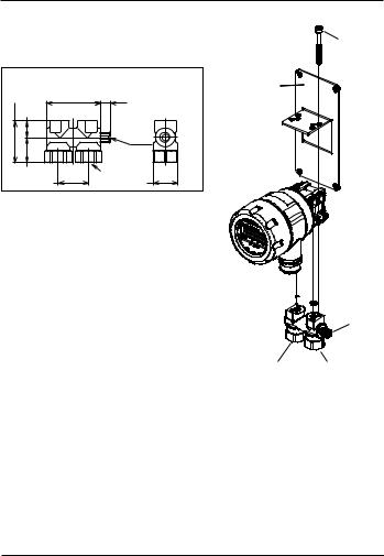
Lower connection diagram
Connection: Lower side.
• 1.0 in. (25.4mm) mounting manifold |
||
1.4 (35) |
1.8 (45.4) |
.33 (8.5) |
.55 (14) |
|
|
|
|
|
|
|
Equalizing |
|
|
valve |
.83 (21) |
|
(2) 1/4˝ NPTF |
1.0 (25.4) |
|
Hex .83 (21) |
M4 x 40
Panel mounting bracket
6.PIPING
Note: High (H) and Low (L) pressure sides of the device are marked on the yellow label affixed to the housing of the unit.
Install the high pressure side of the applied differential pressure in the pressure inlet of the high pressure side (H) and the low pressure side in the pressure inlet of the low pressure side (L).
(Refer to the outline drawing of section 14.) After the piping is completed check for leaks.
O-rings 

Equalizing valve
Low pressure |
High pressure |
inlet (L) |
inlet (H) |
(1) Piping of 1.0 in (25.4mm) Manifold (1⁄4˝ npt female ports)
Use caution when installing to keep metal chips and other debris from entering pressure transmitter. In addition, when sealing tape is used, do not apply to last two threads at the end of the fitting
9

Note:
•When transporting and / or mounting do not apply excessive shock or use device as a step.
•The piping should be of proper length so as not to apply load to the connection point on the transmitter.
•At the time of mounting or when bleeding air from the device be sure to open the equalizing valve with a flathead screwdriver so that excessive pressure (more than the allowable maximum differential pressure) is not applied to the differential pressure sensor. Maximum torque to apply to equalizer valve is 0.75 ft-lbs ±5%.
7.WIRING
7.1Cable/Wire Specifications
Use appropriate cable described below which is suitable for power supply requirements and ground to housing.
Terminal Strip |
SMKDSP1.5/2-5.08 Phoenix Contact |
Cable |
• Two core shielded cable |
Requirements |
• Cable outer diameter: 0.35˝ to 0.47˝ 9-12mm |
|
(Required for correct installation with Cable |
|
Gland option) |
•Wire Gauge: 14-22 AWG (multi-strand or solid)
7.2.Wiring Instructions
•To reduce potential for noise do not run pressure transmitter cable / wires alongside (same conduit as) high voltage (line power) lines. For optimum results use dedicated conduit for PX5200 cable / wires.
•If using the Cable Gland termination option must use cable within previously noted diameters to maintain environmental ratings.
•When connecting shield / drain wire, only connect one end which should be at the receiver ground.
•Wiring stripping instructions, remove cable jacket 2-3˝ and strip wires ±0.25˝. Shield / drain wire should not be exposed at the pressure transmitter termination.
•Remove cover and carefully remove the display to access the terminal strip, take care not to mishandle the display and associated electronics.
10

|
Power source |
Receiver |
|
|
|
|
Transmission cable |
Terminal box
Shield
Display (board)
Notch
CASE
Transmission cab (Twist)
Inside sensor Line
Sheath
DISPLAY
LCD holder
PX5200
CAP
•Turn display over to expose terminal strip, make positive and negative connections,
Wire
insert wire depth is equal to recommended strip length (0.25˝).
Wire terminals
Power supply |
|
terminal block |
Turn with a screwdriver |
|
|
|
LCD clips (4) |
Display board
Display
11
•After completing connections locate retaining clips in the appropriate notches and carefully place into the housing. Be sure that internal sensor transmission wire does not cross the power supply lines just installed.
•If using the Cable Gland be sure to properly tighten sealing grommet before applying any tension on the cable, the cable gland provides strain relief and environmental sealing.
•Tighten GC52 cover to maintain environmental rating.
•Connect to power source and receiver and power on to confirm correct wiring (see Section 10 for more detail).
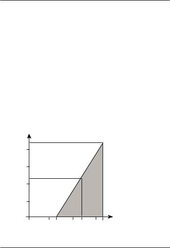
•Power Supply Requirements: Although the 4-20mA signal can travel over long distances one of the most common problems is inadequate power at the pressure transmitter due to the voltage drop across the loop. Be sure to review table below to determine that 12-32V is getting to the pressure transmitter.
Load Limitations 4-20mA Output Only
Loop Resistance (V) |
|
|
|
|
|
|
1020 |
|
|
|
|
|
|
1000 |
|
|
|
|
|
|
750 |
|
|
|
|
|
|
545 |
|
|
|
|
OPERATING |
|
500 |
|
|
|
|
||
|
|
|
|
REGION |
|
|
|
|
|
|
|
|
|
250 |
|
|
|
|
|
|
0 |
|
|
|
|
|
|
0 |
10 |
12 |
20 |
24 |
30 |
32 |
|
|
|
|
|
12 |
|
 Loading...