


Isolated 4 to 20 mA Transmitters For Demanding Applications
Thermocouples, RTD (Pt100) or Ohms, Millivolts, Milliamps, Volts
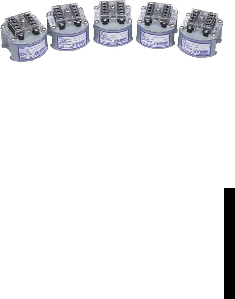
TX1500 Series
Operation
U9 to 50V Compliance
UTurndown Ratio to 10:1
UNMV Protection to 120 Vac
U-40 to 85°C (-40 to 185°F) Operation
UShock Resistance to 55 g
UNEMA 4X (IP66) Metal Case
UField Scalable
Unmatched Electrical
Performance 2-Wire Operation
Power is obtained directly from the 4 to 20 mA loop, with no need for separate power input. This simplifies field wiring and prevents noise pickup from power lines.
TX1502A-K shown actual size.
Isolation to 1500 Vrms (2100 Vp)
This exceptionally high CMV rating from the input to the case or output eliminates electrical ground loops between the signal source and the receiver. It also provides a high degree of protection for the receiver against electrical hazards, such
as accidental contact between the signal source and an AC power line.
9 to 50V Compliance
The loop voltage driving the transmitters can be from 9 to 50V without loss of accuracy. The exceptionally low 9V limit allows the transmitters to be used with low loop supply voltages, and it maximizes the voltage drop allowed
in the current loop for intrinsic safety
N-46
barriers and load resistance. For |
N |
example, at the full 20 mA output |
|
of the transmitter, a 750 Ω load can |
|
be used with a 24 Vdc source and |
|
a 150 Ω load can be used with a |
|
12 Vdc source. In either case, there |
|
will still be enough voltage left to |
|
power the transmitter, namely 9 Vdc. |
|
10:1 Turndown Ratio |
|
Turndown ratio is defined as zero |
|
suppression divided by span. The |
|
exceptionally high 10:1 turndown |
|
ratio possible with the TX1500 |
|
Series indicates that wide zero |
|
offset can be combined with narrow |
|
signal span for closed loop control |
|
at high gain. The signal span can |
|
also be wide for control of batch |
|
operations, where a wide range of |
|
signal levels may be encountered |
|
over the entire batch cycle. |
|
|
|
|
|
Electromagnetic interference (EMI) |
|
|
|
Galvanic isolation |
|
|
|
Signal source: |
|
|
|
|
T/C, RTD, mA |
|
|
|
|
mV, V |
|
4 to 20 mA current loop |
|
|
|
+ |
Sensing |
|
|
|
|
|
||
|
|
|
V = IR |
|
|
- |
|
resistor |
|
|
|
|
||
T/C |
- |
+ |
|
|
|
|
|||
|
|
|
||
Remote |
Isolated 2-wire |
Control room |
|
|
ground |
transmitter |
ground |
|
|
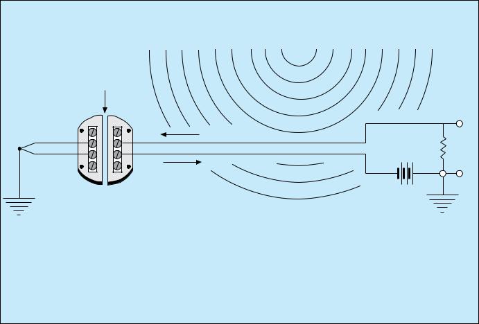
Classic Application of a TX1500 Series 2-Wire Isolated Transmitter
The transmitter amplifies a low-level voltage signal to a 4 to 20 mA current signal, which is immune to voltage noise pickup. . The voltage detected in the control room is V = IR, where I is the loop current and R is the dropping resistor of the receiving equipment. The isolation provided by the transmitter protects the receiving equipment and prevents ground loops between the remote signal ground and the ground of the control room.
High Overvoltage Protection
Overvoltage of 120 Vac may be applied across the input or output leads for 1 minute for all models with voltage or thermocouple inputs. Reverse polarity of 400 Vp may
be applied across the output leads indefinitely. These exceptionally high NMV overvoltage ratings provide further protection against possible electrical faults and wiring errors.
Designed for Harsh Environments
Extreme operating temperatures.
The operating temperature can range from -40 to 85°C (-40 to 185°F) while meeting published performance specifications. This allows the TX1500 Series to be used near furnaces or outdoors in the winter. The exceptionally wide operating temperature range is made possible by a proprietary electrical circuit and by extensive use of computer-graded and computer-matched electrical components.
Resistance to shock and vibration.
The shock rating is 55 g (1.9 oz), which includes a 1.8 m (6') drop onto concrete. This is made possible by a compact die-cast metal case,
which is only 74 mm (2.9") in diameter, and by rugged mounting of the electronics. The circuit board assembly is in the shape of a rigid box and is firmly soldered to the top of the transmitter case.
Waterproof Case
The case is made of diecast zinc alloy. It is waterproof to 35 kPa
(5 psi) and meets NEMA 4X (IP66) standards. The top of the case
is sealed against the bottom with a fluorosilicone gasket, and the openings in the top of the case for the zero and span adjustment, are sealed with fluorosilicone plugs.
Explosion-Proof
Housing Options
Three external NEMA 7 explosion proof and NEMA 4 (IP65) waterproof, sand-cast, copper-free aluminum enclosures with corrosion-resistant “safety-blue” polyester powder-coating for use in hazardous locations. FM, UL, cUL Certification: Class I, Groups B, C, D; Class II, Groups E, F, G; and Class III, Type 4X. Demko/ATEX Certification: EX II 2 G D EEx d IIC.
Option EPH1-ATEX is a singleheight, all metal housing for a single TX1500 Series transmitter.
N-47
Option EPW2-ATEX is a doubleheight metal enclosure with a glass window for a TX1500 Series transmitter on the bottom and a
TX83A loop powered indicator on top. The TX83A augments the transmitter with an LCD digital readout scaled in engineering units and only adds a 2.5 V drop to the current loop.
Option EPW3-ATEX is a singleheight enclosure for one TX83A loop powered indicator. This option includes 2 female 1⁄2 NPT pipe fittings, all required internal mounting hardware, and mounting flanges for a wall or bulkhead.
Easy to Calibrate and Install
There is no need to specify different models for different ranges of the same signal type. Zero and span are each set by push-on jumpers for coarse range selection and by
a 15-turn precision potentiometer for fine adjustment. The 2 potentiometers are accessible outside the case through openings that are normally sealed by fluorosilicone plugs. To assist in calibration, 2 test terminals provide a 10 mV/mA output (200 mV full scale). The scaling procedure is explained in a comprehensive user’s manual, which is shipped with every unit.
TX1501 shown smaller than actual size.
Quick Selection Guide by Input Type
|
|
Zero |
|
|
|
|
|
Suppression |
Maximum Signal |
Signal Span for |
Input |
Model No. |
Signal Type |
for 4 mA Output |
for 20 mA Output |
4 to 20 mA Output |
Impedance |
TX1501 |
RTD |
-200 to 750°C |
850°C |
100 to 1050°C |
|
Pt100 |
-328 to 1382°1 |
562°F |
180 to 1890°F |
N/A |
|
|
Ω |
0 to 365 Ω |
400 Ω |
35 to 400 Ω |
|
TX1502A-J |
Type J T/C |
-50 to 660°C |
760°C |
100 to 810°C |
5 MΩ |
|
iron-constantan |
-58 to1220°F |
1400°F |
180 to 1458°F |
|
TX1502A-K |
Type K T/C |
-50 to 1272°C |
1372°C |
100 to1422°C |
5 MΩ |
|
chromel-alumel |
-58 to 2322°F |
2502°F |
180 to 2560°F |
|
TX1502A-T |
Type T T/C |
-50 to 350°C |
400°C |
50 to 450°C |
5 MΩ |
|
copper-constantan |
-58 to 662°F |
752°F |
90 to 810°F |
|
TX1502A-E |
Type E T/C |
-50 to 900°C |
1000°C |
100 to 1050°C |
5 MΩ |
|
chromel-constantan |
-58 to1652°F |
1832°F |
180 to 1890°F |
|
TX1504 |
Millivolts |
-30 to 60 mV |
160 mV |
5 to 100 mV |
100 MΩ |
TX1505 |
Milliamps |
-30 to 60 mA |
160 mA |
5 to 100 mA |
1 Ω |
TX1506-1 |
Low volts |
-3.5 to 6.0V |
11V |
0.5 to 5V |
1 MΩ |
TX1506-2 |
High volts |
-35 to 60V |
110V |
5 to 50V |
1 MΩ |
Common Specifications
Signal Output
Connection: 2-wire Linear Range: 4 to 20 mA Maximum Output: 35 mA
Voltage Compliance: 9 to 50 Vdc
Power Supply Rejection: 0.01% of span/V
Input/Output Protection:
CMV, Input to Case or Output: 2100 Vp per HV test, 354 Vp per IEC spacing
CMR, Input to Case or Output:120 dB, DC to 60 Hz NMV Across Output Leads: 120 Vac for 1 min
Reverse Polarity Across Output Leads:
400 Vp
Accuracy: -40 to 85°C (-40 to 185°F)
Hysteresis and Repeatability: ±0.1% of span
6-month Stability Error: ±0.2% of zero suppression
Error Due to 50°C Change in Transmitter Temperature:
Zero Error: ±0.2% of zero suppression Span Error: ±0.2% of span
Environmental
Operating Temperature: -40 to 85°C ( 40 to 185°F) N
Storage Temperature: -55 to 125°C ( 67 to 257°F) Relative Humidity: 0 to 100% (sealed case)
Watertight Proof Pressure: 35 kPa (5 psi)
Shock: 55 g, half sine, 9 to 13 ms duration
Vibration: 1.52 mm (0.06") double amplitude, 10 to 80 Hz cycled
Mechanical
Case Material: Zamak zinc alloy
Gasket Material: Fluorosilicone
Diameter: 74 mm (2.9")
Height, Including Barriers: 53 mm (2.1")
Weight: 380 g (13 oz)
Electrical Connection: #6 screws with wire clamps
Terminal Protection:
Standard: Screw terminal barriers plus barrier strip cover
CPB1 (Optional): Plastic cover for case top (protects T/C screw terminals from air currents)
N-48
 Loading...