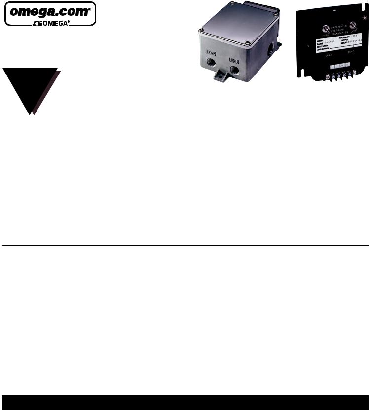
Omega Products PX653 Installation Manual

PX653, PX654, PX655,
PX656, PX657
PRESSURE TRANSDUCER
M1436-0506
INSTRUCTION |
|
|
SHEET |
PX654, PX656 |
PX653, PX655 |
Shop online at: omega.com e-mail: info@omega.com |
||
For latest product manuals: omegamanual.info |
|
|
|
|
|
COMMON SPECIFICATIONS FOR ALL UNITS
Accuracy: ±0.50% FS (BFSL)
(Based on best fit straight line, although NIST cal. sheet is based on terminal point, therefore NIST cal. sheet could report a max. accuracy
of 0.5% TP.) |
|
|
|
|
Linearity: |
|
±0.30% FS (BFSL) |
|
|
Hysteresis: |
|
±0.02% FS |
|
|
Repeatability: |
|
±0.05% FS |
|
|
Operating Temp.: |
|
|
|
|
PX653, PX655: |
|
–20° to 160°F (–29° to 72°C) |
||
PX654, PX656: |
|
–20° to 185°F (–29° to 85°C) |
||
Compensated Temp.: |
|
|
|
|
PX653, PX655: |
|
35° to 135°F (2° to 57°C) |
||
PX654, PX656: |
|
0° to 160°F (–18° to 72°C) |
||
Storage Temp.: |
|
|
|
|
PX653, PX655: |
|
–40 to 180°F |
|
|
PX654, PX656: |
|
–40 to 210°F |
|
|
Proof Pressure: |
PX653 |
15 PSID |
PX654 |
20 PSID |
Burst Pressure: |
PX655 |
{25 PSIS |
PX656 |
{50 PSIS |
Static Pressure: |
|
PX653, PX655 |
25 PSI |
PX654, PX656 |
100 PSI |
Procss Media |
Clean, dry clean non-corrosive |
Thermal Effects: |
gases |
|
|
Zero: |
PX653 ±0.015% FS/°F PX654 ±0.02% |
Span: |
PX655 ±0.015% FS/°F PX656 ±0.02% |
Gage Type |
Capacitance |
Respone Time |
250 ms |
Enclosure: |
|
PX653, PX655 |
NEMA 2 |
PX654, PX656 |
NEMA 4X |
Pressure Port: |
|
PX653, PX655: |
1⁄4 barbed fittings |
PX654, PX656: |
1⁄4 NPTF |
Electrical Connection |
Screw terminal |
PX654, PX656 |
Two 1⁄2 NPTF conduit |
|
PX653 & PX654 (VOLTAGE OUTPUT) |
|
PX655 & PX656 (CURRENT OUTPUT) |
|
||
|
|
|
|
|
|
|
|
EXCITATION: |
12-36Vdc |
|
EXCITATION: |
12-36Vdc |
|
|
OUTPUT: |
1-5Vdc |
|
OUTPUT: |
4-20mA (2 wire) |
|
|
SUPPLY CURRENT: |
<5mA |
|
MAX. LOOP RES.: |
(supply voltage -12) x 50 ohms |
|
|
WEIGHT: |
|
|
WEIGHT: |
|
|
|
PX653: |
14 oz. (397 g) |
|
PX655: |
14 oz. (397 g) |
|
|
PX654: |
2.1 lb. (955 g) |
|
PX656: |
2.1 lb. (955 g) |
|
|
|
|
|
|
||
|
|
|
|
|
|
|
|
HANDLING PRECAUTIONS |
|
CALIBRATION REPORT |
|
||
This sensor has a high insulation resistance. It can be damaged when exposed to high static discharges. Good instrumentation grounding practices should
be used during handling, testing and installation.
All models are tested to meet or exceed the published specifications. Calibration testing was performed using NIST traceable instrumentation. all sensors come calibrated. DO
NOT ATTEMPT TO RECALIBRATE SENSOR, UNLESS YOU HAVE A KNOWN PRESSURE SOURCE THAT IS AT LEAST 5 TIMES MORE ACCURATE THAN THE SENSOR.
WARNING! READ BEFORE INSTALLATION
Fluid hammer and surges can destroy any pressure transducer and must always be avoided. A pressure snubber should be installed to eliminate the damaging hammer effects. Fluid hammer occurs when a liquid flow is suddenly stopped, as with quick closing solenoid valves. Surges occur when flow is suddenly begun, as when pump is turned on to full power or a valve is quickly opened.
Symptoms of fluid hammer and surge’s damaging effects:
1.Pressure transducer exhibits an output at zero pressure (large zero offset). If zero offset is less than 10% FS, user can usually re-zero meter, install proper snubber and continue monitoring pressures.
2.Pressure transducer output remains constant regardless of pressure.
3.In severe cases, there will be no output.
 Loading...