


PX673
ENGINEERING, INC.
®
PX673/675 Series
Flush Diaphragm Pressure Transducer
INSTRUCTION
SHEET
M3423/0699
M3423 8/99 DPS-5C--1P-10//99 Printed in U.S.A.
INSTALLATION INSTRUCTIONS FOR OMEGA
®
FLUSH DIAPHRAGM PRESSURE TRANSDUCER
Mounting
Although the unit can withstand normal
vibration without damage or significant
output effects, it is always good practice to
mount the transducer where there is mini-
mum vibration.
Power Supply
The supply voltage for the 1-5 and 1-6 Vdc
output transducers must be within the
range of 10 to 36 Vdc. The maximum sup-
ply voltage for a 4-20mA current output
transducer is 36 Vdc while the minimum
supply voltage is dependent upon the loop
resistance of the circuit. The figure below
shows the minimum supply voltage (V
min
)
required for a given loop resistance (R
LOOP
).
Noise
For minimum noise susceptibility, avoid
running the transducer's cable in a conduit
that contains high current ac power cables.
Where possible avoid running the cable
near inductive equipment.
Shield Wiring
Connect the braided shield to the guard
terminal on the reading instrument (meter,
etc.) if available or to ground or to the
power supply negative terminal.
Adjustment Potentiometers
The zero and span pots are accessible
through the top of the case. Loosen the col-
lar and separate the top carefully. The zero
pot is marked with a white dot.
Vent Tube
The cable will have a clear Teflon vent tube
that's required at pressure below 500 psi to
provide atmospheric reference. The open
end should be placed in a dry area.
WARNING!
This instrument is susceptible to damage
when exposed to static electrical charges.
To avoid damage to the transducer observe
the following:
• Ground the body of the transducer BEFORE
making any electrical connections
• When disconnecting, remove the ground
LAST.
NOTE: The braided shield and drain wire in
the cable (if supplied) is not connected to the
transducer body, and is not a suitable
ground.
CAUTION: Pressure spikes in excess of the
rated overpressure capability of the trans-
ducer may cause irreversible electrical
and/or mechanical damage to the pressure
measuring and containing element(s).
WARNING: READ BEFORE INSTALLATION
The diaphragm is very sensitive and frag-
ile! Do not let anything touch the
diaphragm but the fluid to be measured.
Fluid hammer and surges can destroy any
pressure transducer and must always be
avoided. A pressure snubber should be
installed to eliminate the damaging ham-
mer effects. Fluid hammer occurs when a
liquid flow is suddenly stopped, as with
quick-closing solenoid valves. Surges occur
when flow is suddenly begun, as when a
pump is turned on at full power or a valve
is quickly opened.
Liquid surges are particularly damaging
to pressure transducers if the pipe is origi-
nally empty. To avoid damaging surges,
fluid lines should remain full (if possible),
pumps should be brought up to power
slowly, and valves opened slowly. To avoid
damage from both fluid hammer and
surges, a surge chamber should be installed.
Symptoms of fluid hammer and surge's
damaging effects:
a) Pressure transducer exhibits an output
at zero pressure(large zero offset). If zero
offset is less than 10% FS, user can usually
re-zero transducer, install proper snub-
ber and continue monitoring pressures.
b) Pressure transducer output remains con-
stant regardless of pressure.
c) In severe cases, there will be no output
.
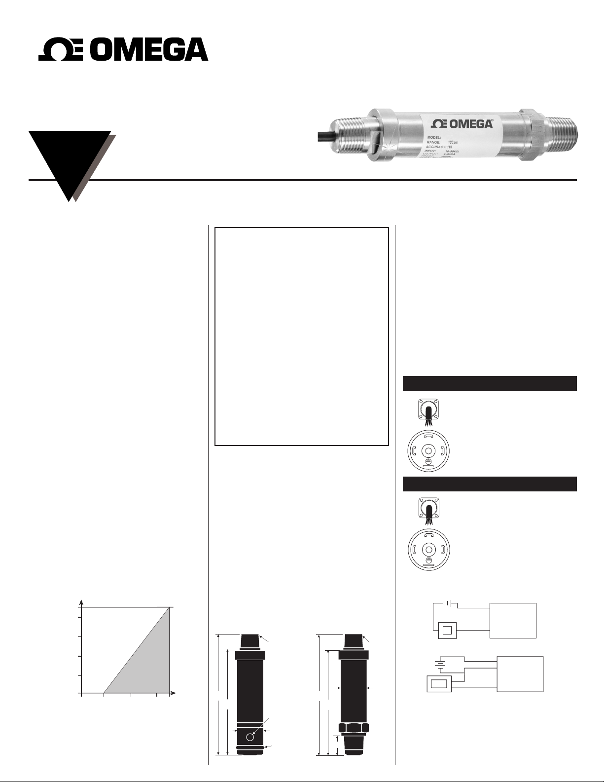
Loop Supply Voltage vs.
Loop Resistance
for 4-20mA Output Only
Loop Supply Voltage (Vdc)
V
min
= 10V + [.022A*(R
L
)]
*includes a 10% safety factor
R
L
= R
S
+ R
W
R
L
= Loop Resistance (ohms)
R
S
= Sense Resistance (ohms)
R
W
= Wire Resistance (ohms)
Loop Resistance (Ohms)
1000
750
500
250
0
0362010
1182
30
6.1
5.2
1/2 NPT
CONDUIT
FITTING
O-RING
SEAL
5/16 18 UNC
THREAD
1.032
4.9
4.2
1/2 NPT
(C1)
1.06
.8
Wiring Diagrams for All Transducers
Electrical Connections
+
+
–
POWER
SUPPLY
(+)
(–)
METER
TRANSDUCER
–
V+
V–
PIN 1
PIN 2
4-20 mA
+
+
–
–
POWER
SUPPLY
METER
TRANSDUCER
(Common)
(+ Power)
(+ Output)
PIN 1
PIN 2
PIN 3
3-Wire Voltage
Cable Type C1
Red = + Power
Black = Common
White = Output
DIN Type
PIN-1 = + Power
PIN-2 = Common
PIN-3 = Output
Cable Type C1
Red = +Power
Black = –Power
DIN Type
PIN-1 = + Power
PIN-2 = –Power
1
2
3
1
2
3
Voltage Output Units 1-5, 1-6 Vdc
Current Output Units 4-20mA
Recalibration Instructions:
1. Apply 0% Full Scale Pressure.
2. Set the output using the
Zero adjustment potentiometer.
3. Apply 100% Full Scale Pressure.
4. Set the output using the
Span adjustment potentiometer.
5. Repeat steps 1 thru 4 as necessary.
 Loading...