

nordictrack.com
Model No. NTSY19916.0
Serial No.
Write the serial number in the space
above for reference.
Serial Number
Decal
ACTIVATE YOUR
WARRANTY
To register your product and
activate your warranty today,
go to my.nordictrack.com.
USER’S MANUAL
CUSTOMER CARE
For service at any time, go to
nordictrackservice.com.
Or call 1-866-608-1798
Mon.–Fri. 6 a.m.–6 p.m. MT
Sat. 8 a.m.–12 p.m. MT
Please do not contact the store.
CAUTION
Read all precautions and
instructions in this manual before
using this equipment. Keep this
manual for future reference.
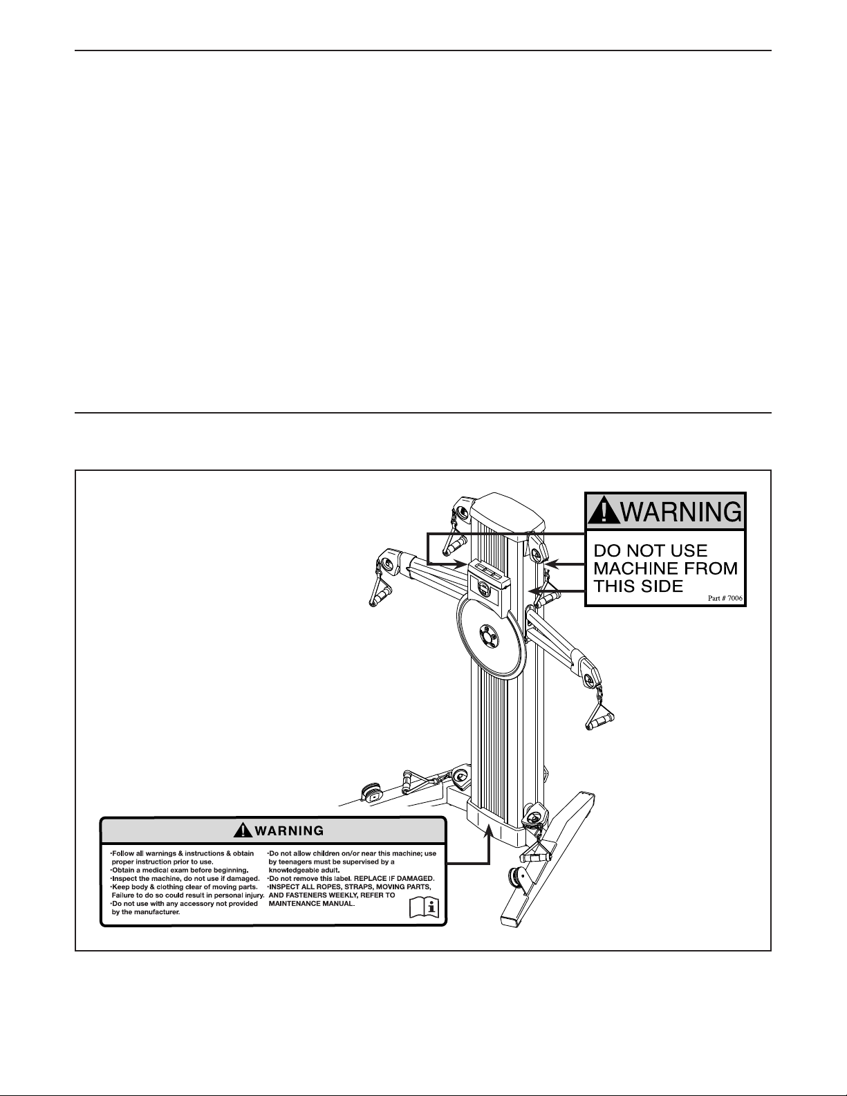
TABLE OF CONTENTS
WARNING DECAL PLACEMENT . . . . . . . . . . . . . . . . . . . . . . . . . . . . . . . . . . . . . . . . . . . . . . . . . . . . . . . . . . . . . . .2
IMPORTANT PRECAUTIONS ..................................................................3
BEFORE YOU BEGIN. . . . . . . . . . . . . . . . . . . . . . . . . . . . . . . . . . . . . . . . . . . . . . . . . . . . . . . . . . . . . . . . . . . . . . . .5
ASSEMBLY . . . . . . . . . . . . . . . . . . . . . . . . . . . . . . . . . . . . . . . . . . . . . . . . . . . . . . . . . . . . . . . . . . . . . . . . . . . . . . . .6
THE CHEST HEART RATE MONITOR. . . . . . . . . . . . . . . . . . . . . . . . . . . . . . . . . . . . . . . . . . . . . . . . . . . . . . . . . .10
HOW TO USE THE STRENGTH SYSTEM. . . . . . . . . . . . . . . . . . . . . . . . . . . . . . . . . . . . . . . . . . . . . . . . . . . . . . . 11
FCC INFORMATION . . . . . . . . . . . . . . . . . . . . . . . . . . . . . . . . . . . . . . . . . . . . . . . . . . . . . . . . . . . . . . . . . . . . . . . .15
MAINTENANCE AND TROUBLESHOOTING .....................................................16
CARDIO EXERCISE GUIDELINES. . . . . . . . . . . . . . . . . . . . . . . . . . . . . . . . . . . . . . . . . . . . . . . . . . . . . . . . . . . . .18
STRENGTH EXERCISE GUIDELINES. . . . . . . . . . . . . . . . . . . . . . . . . . . . . . . . . . . . . . . . . . . . . . . . . . . . . . . . . . 19
PART LIST. . . . . . . . . . . . . . . . . . . . . . . . . . . . . . . . . . . . . . . . . . . . . . . . . . . . . . . . . . . . . . . . . . . . . . . . . . . . . . . .20
EXPLODED DRAWING. . . . . . . . . . . . . . . . . . . . . . . . . . . . . . . . . . . . . . . . . . . . . . . . . . . . . . . . . . . . . . . . . . . . . .22
ORDERING REPLACEMENT PARTS. . . . . . . . . . . . . . . . . . . . . . . . . . . . . . . . . . . . . . . . . . . . . . . . . . . Back Cover
LIMITED WARRANTY. . . . . . . . . . . . . . . . . . . . . . . . . . . . . . . . . . . . . . . . . . . . . . . . . . . . . . . . . . . . . . . Back Cover
WARNING DECAL PLACEMENT
This drawing shows the location(s)
of the warning decal(s). If a decal is
missing or illegible, see the front
cover of this manual and request
a free replacement decal. Apply
the decal in the location shown.
Note: The decal(s) may not be shown
at actual size.
NORDICTRACK is a registered trademark of ICON Health & Fitness, Inc. The BLUETOOTH® word mark and
logos are registered trademarks of Bluetooth SIG, Inc. and are used under license.
2

IMPORTANT PRECAUTIONS
WARNING: To reduce the risk of serious injury, read all important precautions and
instructions in this manual and all warnings on your strength system before using your strength
system. ICON assumes no responsibility for personal injury or property damage sustained by or
through the use of this product.
1. It is the responsibility of the owner to ensure
that all users of the strength system are
adequately informed of all precautions.
2. Before beginning any exercise program,
consult your physician. This is especially
important for persons over age 35 or persons with pre-existing health problems.
3. The strength system is not intended for use
by persons with reduced physical, sensory,
or mental capabilities or lack of experience and knowledge, unless they are given
supervision or instruction about use of the
strength system by someone responsible for
their safety.
4. Use the strength system only as described in
this manual.
5. The strength system is intended for home
use only. Do not use the strength system in a
commercial, rental, or institutional setting.
6. Keep the strength system indoors, away
from moisture and dust. Do not put the
strength system in a garage or covered
patio, or near water.
7. Place the strength system on a level surface
with at least 6 ft. (1.8 m) of clearance around
the strength system. To protect the floor or
carpet from damage, place a mat under the
strength system.
8. Inspect and properly tighten all parts each
time the strength system is used. Replace
any worn parts immediately.
9. Keep children under age 13 and pets away
from the strength system at all times.
10. Wear appropriate clothes while exercising;
do not wear loose clothes that could become
caught on the strength system. Always wear
athletic shoes for foot protection.
11. Keep hands and feet away from moving
parts.
12. Pull and release the handles and ankle straps
in a controlled manner.
13. Make sure that the ropes remain on the pulleys at all times. If the ropes bind while you
are exercising, stop immediately and make
sure that the ropes are on the pulleys.
14. Over exercising may result in serious injury
or death. If you feel faint, if you become short
of breath, or if you experience pain while
exercising, stop immediately and cool down.
3
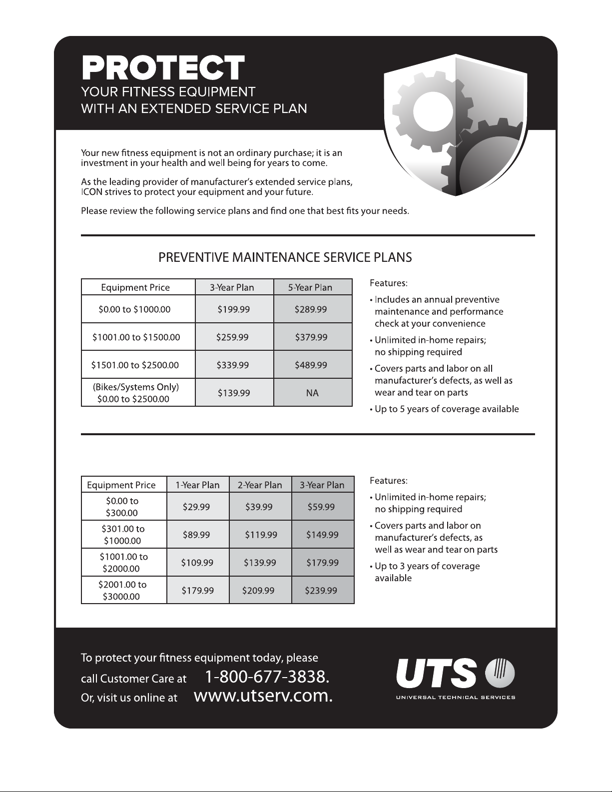
STANDARD SERVICE PLANS
all
4
BEFORE YOU BEGIN
Congratulations for selecting the revolutionary
NORDICTRACK® FUSION CST strength system. The
FUSION CST strength system is unlike any ordinary
strength system. Whether your goal is to tone your
body, build dramatic muscle size and strength, or
improve your cardiovascular system, the strength
system has an array of innovative features that will
help you to achieve the specic results you want.
For your benefit, read this manual carefully before
you use the strength system. If you have questions
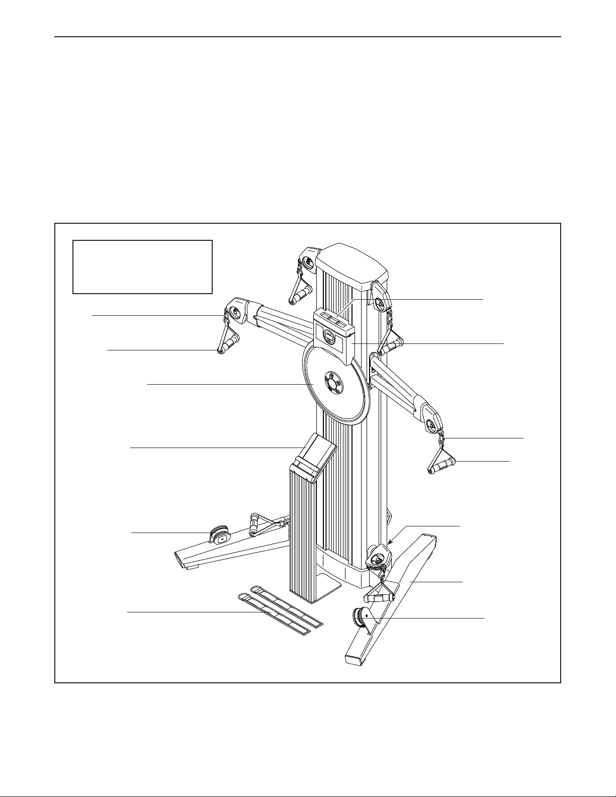
Length: 3 ft. 6 in. (107 cm)
Width: 5 ft. 2 in. (157 cm)
Height: 6 ft. 2 in. (188 cm)
Clip
Handle
after reading this manual, please see the front cover
of this manual. To help us assist you, note the product
model number and serial number before contacting us.
The model number and the location of the serial number decal are shown on the front cover of this manual.
Before reading further, please familiarize yourself with
the parts that are labeled in the drawing below.
Tablet Holder
Console
Resistance Disc
Tablet Stand
Squat Pulley
Ankle Strap
Clip
Handle
Power Receptacle
Freestanding Leg
Squat Pulley
5
ASSEMBLY
• Due to the size and weight of the strength system,
assembly requires two or three persons.
• Place all parts in a cleared area and remove the
packing materials. Do not dispose of the packing
materials until you nish all assembly steps.
• Left parts are marked “L” or “Left” and right parts
are marked “R” or “Right.”
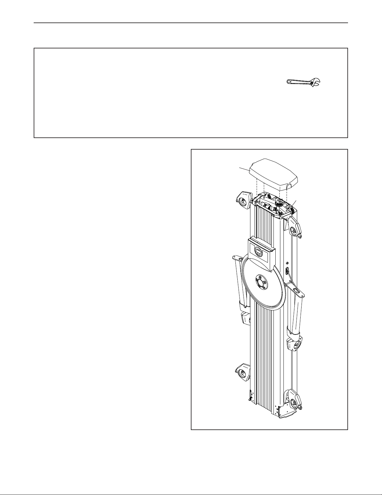
1. Orient the Tower Top Cover (2) as shown, and
press it onto the top of the Frame (1).
• In addition to the included tool(s), assembly
requires the following tools:
one adjustable wrench
Assembly may be easier if you have your own set
of wrenches. To avoid damaging parts, do not use
power tools.
1
2
1
6
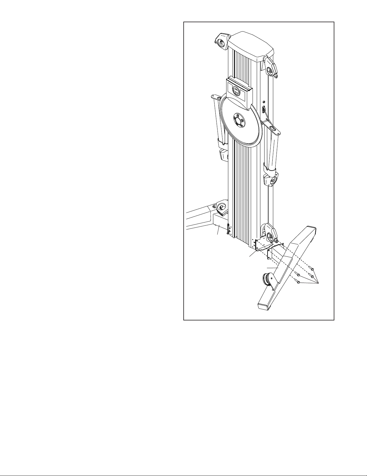
2. Tip: To protect the floor or carpet from
damage, place a mat under the strength
system.
Attach the Right Leg (44) to the right side of the
Frame (1) with four M10 x 25mm Hex Screws
(101); start all the Hex Screws, and then
tighten them.
Attach the Left Leg (66) in the same way.
2
66
1
44
101
7
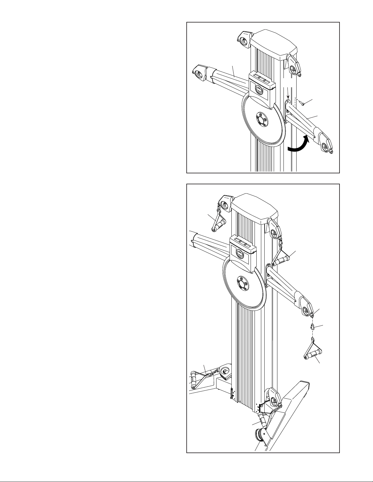
3. Tip: Avoid pinching the Rope (not shown).
With the help of another person, pivot the right
Tower Arm (19) upward and secure it to the
Frame (1) with an M10 x 30mm Screw (100).
3
Repeat this step for the left Tower Arm (19).
4. Attach a Handle (37) to a Rope End (35) with a
Clip (36).
Attach the other Handles (37) in the same
way.
19
1
100
19
4
37
37
37
35
36
37
37
8

5. Identify the Front and Rear Bottom Covers
(67, 109) and press them into place as shown.
5
109
67
6. Plug the Power Adapter (126) into the receptacle
on the rear of the strength system.
Note: To plug the Power Adapter (126) into an
outlet, see HOW TO PLUG IN THE POWER
ADAPTER on page 11.
7. Go to my.nordictrack.com on your computer
and register your product.
• documents your ownership
• activates your warranty
• ensures priority customer support if assistance
is ever needed
6
126
7
Note: If you do not have internet access, call
Customer Care (see the front cover of this
manual) and register your product.
8. Make sure that all parts have been properly tightened. The use of the remaining parts will be explained in
HOW TO USE THE STRENGTH SYSTEM, beginning on page 11.
Before using the strength system, pull each handle a few times to make sure that the ropes move smoothly
around the pulleys. If one of the ropes does not move smoothly, find and correct the problem.
9

THE CHEST HEART RATE MONITOR
HOW TO PUT ON THE HEART RATE MONITOR
If the heart rate monitor looks like the one shown in
drawing 1, press the transmitter (A) onto the snap fas-
teners on the chest strap (B). If the heart rate monitor
looks like the one shown in drawing 2, insert the tab
(C) on one end of the chest strap (D) into one end of
the transmitter (E). Then, press the end of the transmitter under the buckle (F) on the chest strap; the tab
should be flush with the transmitter.
1
B
A
Next, wrap the heart
rate monitor around
your chest in the location shown; the heart
rate monitor must be
under your clothes,
tight against your skin.
Make sure that the logo
is right-side-up. Then, attach the other end of the chest
strap. Adjust the length of the chest strap, if necessary.
2
C
E
D
F
• Store the heart rate monitor in a warm, dry place. Do
not store the heart rate monitor in a plastic bag or
other container that may trap moisture.
• Do not expose the heart rate monitor to direct
sunlight for extended periods of time, and do not
expose it to temperatures above 122°F (50°C) or
below 14°F (-10°C).
• Do not excessively bend or stretch the heart rate
monitor when using or storing it.
• To clean the transmitter, use a damp cloth and a
small amount of mild soap. Then, wipe the transmitter with a damp cloth and thoroughly dry it with a soft
towel. Never use alcohol, abrasives, or chemicals
to clean the transmitter. Hand wash and air dry the
chest strap.
TROUBLESHOOTING
• If the heart rate monitor does not function when
positioned as described at the left, move it slightly
lower or higher on your chest.
• If heart rate readings are not displayed until you
begin perspiring, re-wet the electrode areas.
• For the console to display heart rate readings, you
must be within arm’s length of the console.
Next, pull the transmitter and the chest
strap away from your
body a few inches
and locate the two
electrode areas (G).
Using saliva or contact lens solution, wet the electrode areas. Then, return
the transmitter and the chest strap to a position against
your chest.
CARE AND MAINTENANCE
• Thoroughly dry the electrode areas with a soft towel
after each use. Moisture may keep the heart rate
monitor activated, shortening the life of the battery.
G
• If there is a battery cover on the back of the transmitter, replace the battery with a new battery of the
same type.
• The heart rate monitor is designed to work with
people who have normal heart rhythms. Heart rate
reading problems may be caused by medical conditions such as premature ventricular contractions
(pvcs), tachycardia bursts, and arrhythmia.
• The operation of the heart rate monitor can be
affected by magnetic interference from high power
lines or other sources. If you suspect that magnetic
interference is causing a problem, try relocating the
fitness equipment.
10

HOW TO USE THE STRENGTH SYSTEM
This section explains how to adjust the strength system. See the EXERCISE GUIDELINES on page 18 and
page 19 for important information about how to get the most benefit from your exercise program. Also, refer to
the accompanying exercise guide to see the correct form for each exercise.
Make sure that all parts are properly tightened each time the strength system is used. Replace any worn parts
immediately.
HOW TO PLUG IN THE POWER ADAPTER
IMPORTANT: If the strength system has been
exposed to cold temperatures, allow it to warm
to room temperature before you plug in the
Power Adapter (126). If you do not do this, you
may damage the console displays or other electronic components.
Plug the Power Adapter (126) into the receptacle
on the rear of the strength system. Then, plug the
Power Adapter into an appropriate outlet that is
properly installed in accordance with all local codes
and ordinances.
HOW TO ATTACH THE HANDLES AND ANKLE
STRAPS
Attach a Handle (37) or an Ankle Strap (53) to a
Rope End (35) with a Clip (36). Attach the other
Handles or Ankle Strap in the same way.
37
126
37
11
35
36
37
53

HOW TO USE THE TABLET HOLDER
IMPORTANT: The Tablet Holder (68) is designed
for use with most full-size tablets. Do not place
any other electronic device or object in the
Tablet Holder. Do not set anything on top of the
Tablet Holder.
To insert a tablet into the Tablet Holder (68), slide it
upward, set the tablet in the tray (A), and then pull
the Tablet Holder downward over the top edge of the
tablet. Make sure that the tablet is firmly secured
in the Tablet Holder. Reverse these actions to
remove the tablet from the Tablet Holder.
HOW TO USE THE TABLET STAND
68
A
IMPORTANT: The Tablet Stand (15) is designed
for use with most full-size tablets. Do not place
any other electronic device or object in the
Tablet Stand.
To insert a tablet into the Tablet Stand (15), lift the
slide (B) upward, and then set the tablet in the tray
(C). Then, pull the slide downward over the top
edge of the tablet. Make sure that the tablet is
firmly secured in the Tablet Stand. Reverse these
actions to remove the tablet from the Tablet Stand.
HOW TO USE THE SQUAT PULLEYS
Pull a lower Handle (37) outward and route the
Rope (52) under the Squat Pulley (64); make sure
that the Rope is securely routed under the Squat
Pulley.
B
C
15
Repeat this action for the other Squat Pulley (not
shown).
12
37
52
64

CONSOLE DIAGRAM
FEATURES OF THE CONSOLE
The advanced console offers an array of features
designed to make your workouts more effective and
enjoyable.
Interactive iFit App
Download the interactive iFit app to access the
advanced features of your FUSION CST.
The iFit app provides you with an interactive and
immersive workout experience, with high-energy,
time-saving combination strength and cardio workouts led by virtual personal trainers. Each iFit workout
automatically adjusts the resistance of the strength
system as you exercise.
Using the iFit app, you can also record and track your
workout and health information so you can see your
progress towards your fitness goals.
Manual Workouts
You can also perform manual workouts with the
strength system. While you exercise, you can change
the resistance of the strength system with the touch of
a button. The console will display continuous exercise
feedback about your power output in watts.
Chest Heart Rate Monitor
During your workouts, you can measure your heart rate
using the included chest heart rate monitor.
To download the iFit app, see this page. To use the
console, see page 14. To connect your heart rate
monitor to the console, see page 15.
Note: If there is a sheet of plastic on the display,
remove the plastic.
HOW TO DOWNLOAD THE IFIT APP
Using the included 10" tablet for Android™, open a web
browser and go to iFit.com/apps.
Follow the instructions on the website to download the
appropriate iFit app. Make sure that the BLUETOOTH
option is enabled on your device.
Then, open the iFit app and follow the instructions to
set up an iFit account, customize settings, and get
started using iFit workouts, setting goals, and tracking
your progress.
13

HOW TO USE THE CONSOLE
1. Press the power button to turn on the console.
When you turn on the console, the display will turn
on. The console will then be ready for use.
2. Begin exercising and change the resistance as
desired.
4. Wear the included chest heart rate monitor and
measure your heart rate if desired.
You can wear the included chest heart rate moni-
tor to measure your heart rate. To use the chest
heart rate monitor, see THE CHEST HEART RATE
MONITOR on page 10. Note: The console is
compatible with all BLUETOOTH® Smart heart rate
monitors.
As you exercise, change the resistance by pressing
the increase and decrease buttons.
Note: After you press a button, it will take a
moment for the strength system to reach the
selected resistance level.
3. Follow your progress with the displays.
The console can show the following workout
information:
Heart Rate (heart
symbol)—This display
will show your heart
rate in beats per minute when you wear the
included chest heart
rate monitor (see step 4).
Resistance—This
display will show the
resistance level for a
few seconds each time
the resistance level
changes.
Watts—This display
will show your approximate maximum power
output in watts for
each stroke.
To connect your heart rate monitor to the console,
see HOW TO CONNECT YOUR HEART RATE
MONITOR TO THE CONSOLE on page 15.
When your heartbeat is detected, your heart rate
will be shown in the display.
5. Stop exercising and view your exercise
summary if desired.
A few moments after you stop exercising, the
console will pause and show your exercise
summary:
Calories (Cal)—This
display will show the
approximate number
of calories you have
burned during your
workout.
Average Maximum
Power Output
(Ave)—This display
will show your average maximum power
output in watts for your
workout.
Note: If you do not resume exercising after a few
moments, the workout information will be reset and
the display will turn off.
Watts Meter—The
watts meter will light
up to provide a visual
representation of your
approximate maximum
power output in watts
for each stroke.
6. When you are finished exercising, turn off the
console.
Press the power button repeatedly to turn off the
console manually. The console will enter a pause
mode, display the exercise summary, enter a
countdown mode, and then reset the workout information and turn off the display.
If the strength system is idle for several minutes,
the console will turn off automatically.
14

HOW TO CONNECT YOUR HEART RATE MONITOR
TO THE CONSOLE
To use the included chest heart rate monitor, see THE
CHEST HEART RATE MONITOR on page 10.
Note: The console is compatible with all BLUETOOTH
Smart heart rate monitors.
To connect your heart rate monitor to the console,
press the Bluetooth Smart button on the console; the
console pairing number will appear in the display.
When a connection is established, the LED on the
console will flash red twice.
Note: If there is more than one compatible heart rate
monitor near the console, the console will connect to
the heart rate monitor with the strongest signal.
To disconnect your heart rate monitor from the console,
press and hold the Bluetooth Smart button on the console until the LED on the console turns solid green.
Note: All BLUETOOTH connections between the
console and other devices (including any tablets, heart
rate monitors, and so forth) will be disconnected.
FCC INFORMATION
This equipment has been tested and found to comply with the limits for a Class B digital device, pursuant to part
15 of the FCC Rules. These limits are designed to provide reasonable protection against harmful interference
in a residential installation. This equipment generates, uses, and can radiate radio frequency energy and, if not
installed and used in accordance with the instructions, may cause harmful interference to radio communications.
However, there is no guarantee that interference will not occur in a particular installation. If this equipment does
cause harmful interference to radio or television reception, which can be determined by turning the equipment off
and on, try to correct the interference by one or more of the following measures:
• Reorient or relocate the receiving antenna.
• Increase the separation between the equipment and the receiver.
• Connect the equipment into an outlet on a circuit different from that to which the receiver is connected.
• Consult the dealer or an experienced radio/TV technician for help.
FCC CAUTION: To assure continued compliance, use only shielded interface cables when connecting to
computer or peripheral devices. Changes or modifications not expressly approved by the party responsible for compliance could void the user’s authority to operate this equipment.
15

MAINTENANCE AND TROUBLESHOOTING
HOW TO MAINTAIN THE STRENGTH SYSTEM
Regular maintenance is important for optimal
performance and to reduce wear. Inspect and properly
tighten all parts each time the strength system is used.
Replace any worn parts immediately.
To clean the strength system, use a damp cloth and
a small amount of mild detergent. IMPORTANT: To
avoid damage to the console, keep liquids away
from the console and keep the console out of
direct sunlight.
CONSOLE TROUBLESHOOTING
If the console does not turn on, make sure that the
power adapter is fully plugged in.
If the console does not display your heart rate
when you use the chest heart rate monitor, see
TROUBLESHOOTING on page 10.
If a replacement power adapter is needed, call the
telephone number on the cover of this manual.
IMPORTANT: To avoid damaging the console, use
only a manufacturer-supplied regulated power
adapter.
HOW TO ADJUST THE REED SWITCH
If the console does not display correct feedback, the
reed switch should be adjusted.
To adjust the reed switch, first unplug the power
adapter, and then follow the steps below.
See EXPLODED DRAWING B on page 23. Identify
the Rear Shroud (59). Remove the four #8 x 3/4"
Screws (86) and the Rear Shroud from the strength
system.
Next, locate the Reed Switch (25). Slightly loosen the
indicated screw (A).
119
6
25
Then, rotate the Resistance Disc (6) until a Magnet
(119) is aligned with the Reed Switch (25). Slide the
Reed Switch slightly toward or away from the Magnet.
Then, retighten the screw (A).
Plug in the power adapter and rotate the Resistance
Disc (6) for a moment. Repeat these actions until the
console displays correct feedback.
When the reed switch is correctly adjusted, reattach
the parts that you removed. Then, plug in the power
adapter.
A
See assembly step 5 on page 9. Remove the
Front and Rear Bottom Covers (67, 109) from the
bottom of the strength system.
16

HOW TO TIGHTEN THE ROPES
The ropes may stretch over time. If there is slack in
the ropes before resistance is felt, the ropes should be
tightened. To tighten the ropes, first unplug the power
adapter, and then follow the steps below.
See assembly step 5 on page 9. Remove the
Front and Rear Bottom Covers (67, 109) from the
bottom of the strength system.
See EXPLODED DRAWING B on page 23. Identify
the Rear Shroud (59) on the back of the strength system. Remove the four #8 x 3/4" Screws (86) and the
Rear Shroud from the strength system.
See the drawing at the right. Locate a Pulley
Carriage (46). Remove the M8 Jam Nut (106), the
M8 x 33mm Bolt (112), and the Small Pulley (55) from
the upper hole in the Pulley Carriage.
Reattach the Small Pulley (55) to the other hole in the
Pulley Carriage (46). Make sure that the Rope (105)
and the Small Pulley move smoothly.
Locate the other Pulley Carriage (46) and repeat
these actions.
Then, reattach the parts that you removed. Plug in the
power adapter.
46
106
46
105
55
112
17

CARDIO EXERCISE GUIDELINES
Burning Fat—To burn fat effectively, you must exer-
WARNING: Before beginning this
or any exercise program, consult your physician. This is especially important for persons
over age 35 or persons with pre-existing
health problems.
The heart rate monitor is not a medical device.
Various factors may affect the accuracy of
heart rate readings. The heart rate monitor is
intended only as an exercise aid in determining heart rate trends in general.
These guidelines will help you to plan your exercise
program. For detailed exercise information, obtain a
reputable book or consult your physician. Remember,
proper nutrition and adequate rest are essential for
successful results.
EXERCISE INTENSITY
Whether your goal is to burn fat or to strengthen your
cardiovascular system, exercising at the proper intensity is the key to achieving results. You can use your
heart rate as a guide to find the proper intensity level.
The chart below shows recommended heart rates for
fat burning and aerobic exercise.
cise at a low intensity level for a sustained period of
time. During the first few minutes of exercise, your
body uses carbohydrate calories for energy. Only after
the first few minutes of exercise does your body begin
to use stored fat calories for energy. If your goal is to
burn fat, adjust the intensity of your exercise until your
heart rate is near the lowest number in your training
zone. For maximum fat burning, exercise with your
heart rate near the middle number in your training
zone.
Aerobic Exercise—If your goal is to strengthen your
cardiovascular system, you must perform aerobic
exercise, which is activity that requires large amounts
of oxygen for prolonged periods of time. For aerobic
exercise, adjust the intensity of your exercise until your
heart rate is near the highest number in your training
zone.
WORKOUT GUIDELINES
Warming Up—Start with 5 to 10 minutes of stretch-
ing and light exercise. A warm-up increases your body
temperature, heart rate, and circulation in preparation
for exercise.
Training Zone Exercise—Exercise for 20 to 30 minutes with your heart rate in your training zone. (During
the first few weeks of your exercise program, do not
keep your heart rate in your training zone for longer
than 20 minutes.) Breathe regularly and deeply as you
exercise ; never hold your breath.
To find the proper intensity level, find your age at the
bottom of the chart (ages are rounded off to the nearest ten years). The three numbers listed above your
age define your “training zone.” The lowest number is
the heart rate for fat burning, the middle number is the
heart rate for maximum fat burning, and the highest
number is the heart rate for aerobic exercise.
Cooling Down—Finish with 5 to 10 minutes of stretching. Stretching increases the flexibility of your muscles
and helps to prevent post-exercise problems.
EXERCISE FREQUENCY
To maintain or improve your condition, complete three
workouts each week, with at least one day of rest
between workouts. After a few months of regular exercise, you may complete up to five workouts each week,
if desired. Remember, the key to success is to make
exercise a regular and enjoyable part of your everyday
life.
18

STRENGTH EXERCISE GUIDELINES
FOUR TYPES OF STRENGTH WORKOUTS
Note: A “repetition” is one complete cycle of an
exercise, such as one sit-up. A “set” is a series of
repetitions.
Muscle Building—Work your muscles near their maximum capacity and progressively increase the intensity
of your exercise. Adjust the intensity level of an individual exercise as follows:
• Change the amount of resistance used.
• Change the number of repetitions or sets performed.
Use your own judgment to determine the amount of
resistance that is right for you. Begin with 3 sets of 8
repetitions for each exercise you perform. Rest for 3
minutes after each set. When you can complete 3 sets
of 12 repetitions without difficulty, increase the amount
of resistance.
Toning—Tone your muscles by working them to a
moderate percentage of their capacity. Select a moderate amount of resistance and increase the number of
repetitions in each set. Complete as many sets of 15 to
20 repetitions as possible without discomfort. Rest for
1 minute after each set. Work your muscles by completing more sets rather than by using high amounts of
resistance.
Weight Loss—To lose weight, use a low amount of
resistance and increase the number of repetitions in
each set. Exercise for 20 to 30 minutes, resting for a
maximum of 30 seconds between sets.
Cross Training—Combine strength training and aerobic exercise by following this type of program:
• Strength training workouts on Monday, Wednesday,
and Friday.
• 20 to 30 minutes of aerobic exercise on Tuesday and
Thursday.
• One full day of rest each week to give your body time
to regenerate.
WORKOUT GUIDELINES
Familiarize yourself with the equipment and learn the
proper form for each exercise. Use your own judgment
to determine the appropriate length of time for each
workout, and the numbers of repetitions and sets to
complete. Progress at your own pace and be sensitive
to your body’s signals. Follow each workout with at
least one day of rest.
Warming Up—Start with 5 to 10 minutes of stretching and light exercise. A warm-up increases your body
temperature, heart rate, and circulation in preparation
for exercise.
Working Out—Include 6 to 10 different exercises in
each workout. Select exercises for every major muscle
group, emphasizing areas that you want to develop.
To give balance and variety to your workouts, vary the
exercises from workout to workout.
Cooling Down—Finish with 5 to 10 minutes of stretching. Stretching increases the flexibility of your muscles
and helps to prevent post-exercise problems.
EXERCISE FORM
Move through the full range of motion for each exercise and move only the appropriate parts of the body.
Perform the repetitions in each set smoothly and
without pausing. The exertion stage of each repetition should last about half as long as the return stage.
Exhale during the exertion stage of each repetition and
inhale during the return stroke. Never hold your breath.
Rest for a short period of time after each set:
• Muscle Building—Rest for three minutes after each
set.
• Toning—Rest for one minute after each set.
• Weight Loss—Rest for 30 seconds after each set.
STAYING MOTIVATED
For motivation, keep a record of each workout. Write
the date, the exercises performed, the resistance used,
and the numbers of sets and repetitions completed.
Record your weight and key body measurements once
a month. To achieve good results, make exercise a
regular and enjoyable part of your life.
19

PART LIST
Key No. Qty. Description Key No. Qty. Description
Model No. NTSY19916.0 R0518A
1 1 Frame
2 1 Tower Top Cover
3 2 Spring
4 2 Spring Cover
5 1 Disc Cover
6 1 Resistance Disc
7 1 Resistance Axle
8 6 Retention Ring
9 6 Main Bearing
10 1 Front Hub Spacer
11 2 Bearing Spacer
12 2 Pulley Hub
13 2 Mechanism Pulley
14 1 Pulley Spacer
15 1 Tablet Stand
16 1 Tower Bracket
17 1 Slide Frame Bracket
18 1 Resistance Arm Assembly
19 2 Tower Arm
20 2 Upper Tower Cover
21 1 Resistance Disc
22 1 Resistance Motor
23 1 Reed Switch Bracket
24 1 Reed Switch Clamp
25 1 Reed Switch/Wire
26 2 Tower Arm Cover
27 6 Swivel Bearing
28 6 Snap Ring
29 6 Counterweight
30 3 Right Pulley Cover A
31 3 Right Pulley Cover B
32 6 Swivel Pulley Axle
33 6 Swivel Pulley
34 6 Rope Collar
35 6 Rope End
36 6 Clip
37 6 Handle
38 1 Right Tower Cover
39 2 Eyebolt
40 2 Bumper
41 1 Power Receptacle/Wire
42 1 Rear Hub Spacer
43 1 Left Tower Cover
44 1 Right Leg
45 4 Foot
46 2 Pulley Carriage
47 2 Cable Trap
48 2 D Sensor
49 4 Standoff
50 1 Tall Sensor Bracket
51 1 Short Sensor Bracket
52 2 201" Rope
53 2 Ankle Strap
54 4 Arm Pulley Spacer
55 5 Small Pulley
56 15 Large Pulley
57 1 Shroud Cover
58 1 Front Shroud
59 1 Rear Shroud
60 1 Right Leg Shield
61 2 M6 x 12mm Screw
62 2 M6 Washer
63 4 Outer Guide
64 2 Squat Pulley
65 1 Disc Shield
66 1 Left Leg
67 1 Front Bottom Cover
68 1 Tablet Holder
69 1 Tablet Holder Bracket
70 1 Slide Frame
71 1 Magnet Bracket
72 1 Light Bar
73 1 Console
74 4 Snap Clip
75 8 Tree Fastener
76 8 #4 x 6mm Screw
77 6 M4 x 5mm Set Screw
78 4 M4 x 12mm Bolt
79 12 M4 x 30mm Machine Screw
80 2 #6 x 3/8" Screw
81 2 #8 x 3/8" Screw
82 1 #8 x 1/2" Console Screw
83 8 #8 x 1/2" Screw
84 4 #8 x 5/8" Screw
85 4 #8 x 3/4" Tek Screw
86 30 #8 x 3/4" Screw
87 4 #8 x 1 1/4" Screw
88 8 M6 x 16mm Screw
89 3 M6 x 20mm Hex Screw
90 4 M8 x 35mm Bolt
91 2 M8 x 115mm Bolt
92 5 M10 x 25mm Flat Head Screw
93 2 M10 x 67mm Bolt
94 3 M6 x 13mm Screw
95 4 M4 Locknut
96 2 M6 Nut
97 4 M8 Locknut
98 2 M10 Locknut
99 4 Zip Tie
100 2 M10 x 30mm Screw
20

Key No. Qty. Description Key No. Qty. Description
101 8 M10 x 25mm Hex Screw
102 1 Left Leg Shield
103 1 73" Rope
104 1 82" Rope
105 2 169 1/2" Rope
106 19 M8 Jam Nut
107 11 M8 x 30mm Bolt
108 1 M8 x 30mm Patch Screw
109 1 Rear Bottom Cover
110 2 #8 x 5/8" Flat Head Screw
111 2 #8 x 1 3/8" Screw
112 5 M8 x 33mm Bolt
113 1 M8 x 68mm Bolt
114 1 M10 Washer
115 3 Left Pulley Cover A
Note: Specifications are subject to change without notice. For information about ordering replacement parts, see
the back cover of this manual. *These parts are not illustrated.
116 3 Left Pulley Cover B
117 6 M4 x 20mm Screw
118 6 M4 x 25mm Screw
119 36 Magnet
120 4 M8 Washer
121 7 Mounted Zip Tie
122 1 Sensor Wire
123 1 Extension Wire
124 1 #8 x 5/8" Tek Screw
125 1 Main Wire
126 1 Power Adapter
127 4 #8 x 3/4" Machine Screw
128 1 #6 x 3/8" Screw
129 1 Chest Heart Rate Monitor
* – User’s Manual
21

EXPLODED DRAWING A
Model No. NTSY19916.0 R0518A
90
52
16
89
114
97
40
9
2
107
56
90
113
8
42
104
103
22
95
74
107
56
97
86
47
112
13
106
8
9
11
12
88
9
8
14
119
78
18
84
21
17
20
128
107
11
106
55
56
13
8
107
56
106
106
86
9
8
10
12
88
9
108
91
106
107
124
121
23
100
47
86
93
120
24
54
91
25
120
54
79
86
39
96
56
31
29
27
54
28
120
118
19
106
32
26
99
112
55
46
106
44
117
34
35
36
77
33
30
3
4
37
106
101
99
106
56
38
107
60
56
106
56
107
101
63
64
63
62
61
89
105
74
117
86
43
92
111
37
45
66
45
85
37
82
87
99
84
37
79
116
29
19
118
27
28
33
32
34
35
76
36
115
48
48
49
49
37
51
80
50
98
9
8
76
76
6
94
1
4
5
99
102
7
94
92
22

EXPLODED DRAWING B
Model No. NTSY19916.0 R0518A
125
86
83
59
83
109
58
75
75
122
86
123
126
41
75
86
129
68
69
86
83
86
73
57
127
81
65
75
67
110
70
81
53
71
15
72
23

ORDERING REPLACEMENT PARTS
To order replacement parts, please see the front cover of this manual. To help us assist you, be prepared to
provide the following information when contacting us:
• the model number and serial number of the product (see the front cover of this manual)
• the name of the product (see the front cover of this manual)
• the key number and description of the replacement part(s) (see the PART LIST and the EXPLODED DRAWING
near the end of this manual)
LIMITED WARRANTY
IMPORTANT: To protect your fitness equipment with an extended service plan, see page 4.
ICON Health & Fitness, Inc. (ICON) warrants this product to be free from defects in workmanship and
material, under normal use and service conditions. The frame is warranted for the lifetime of the original
purchaser (customer). Parts and labor are warranted for one (1) year from the date of purchase.
This warranty extends only to the original purchaser (customer) and is not transferrable. ICON’s obligation under this warranty is limited to repairing or replacing, at ICON’s option, the product through one of
its authorized service providers. All repairs for which warranty claims are made must be preauthorized by
ICON. If replacement parts are shipped while the product is under warranty, the customer will be responsible for a minimal handling charge. For in-home service, the customer may be responsible for a minimal
trip charge. This warranty does not extend to freight damage to the product. This warranty will automatically be voided by the following conditions: (1) if the product is used as a store display model, (2) if the
product is purchased or transported outside the USA, (3) if all instructions and warnings in this manual are
not followed, (4) if the product is abused or improperly or abnormally used, or (5) if the product is used for
commercial or rental purposes. No other warranty beyond that specically set forth above is authorized
by ICON.
ICON is not responsible or liable for the following damages: (1) indirect, special, or consequential damages arising out of or in connection with the use or performance of the product; (2) damages with respect
to any economic loss, loss of property, loss of revenues or prots, loss of enjoyment or use, or costs of
removal or installation; or (3) other consequential damages of any kind. Some states do not allow the
exclusion or limitation of incidental or consequential damages. Accordingly, the above limitation may not
apply to the customer.
The warranty extended hereunder is in lieu of any and all other warranties, and any implied warranties of
merchantability or tness for a particular purpose are limited in their scope and duration to the terms set
forth herein. Some states do not allow limitations on how long an implied warranty lasts. Accordingly, the
above limitation may not apply to the customer. This warranty provides specic legal rights; the customer
may have other rights that vary from state to state.
For warranty service, please call the telephone number on the front cover of this manual. Please be prepared to provide the model number and serial number of the product (see the front cover of this manual).
ICON Health & Fitness, Inc., 1500 S. 1000 W., Logan, UT 84321-9813
Part No. 387621 R0518A Printed in China © 2016 ICON Health & Fitness, Inc.
 Loading...