


INC
JAA78451-R.3596.A
AF-S DXZoom-Nikkor ED 12-24mm f/4G IF
REPAIR MANUAL
NIKON CORPORATION
Tokyo, Japan
|
Copyright 2003 by Nikon Corporation. |
Recycled paper |
All Rights Reserved. |
Printed in Japan March 2003
INC
JAA78451-R.3596.A
SPECIFICATIONS
This lens can be used for Nikon digital SLR camera only.
Type of lens |
G-type AF ZoomNikkor lens having built-in CPU and Nikon F bayonet mount |
|
|
Focal length |
12mm - 24mm (18 - 36 mm in 35 mm format) |
|
|
Maximum aperture |
f/4 |
|
|
Lens construction |
11 elements in 7 groups (3 aspherical lens and 2 ED lens elements) |
|
|
Picture angle |
99°- 61°(with Nikon Digital Camera D1/D1H/D1X/D100) |
|
|
Focal length scale |
12,15,18,20,24mm |
|
|
Distance information |
Output to camera body |
|
|
Zoom control |
Manually via separate zoom ring |
|
|
Focusing |
Nikon Internal Focusing (IF) system (utilizing an internal Silent Wave Motor); |
|
manually via separate focus ring |
|
|
Shooting distance scale |
Graduated in meters and feet from 0.3m (1ft.) to infinity (∞) |
|
|
Closest focus distance |
0.3m (1ft.) at all zoom settings |
|
|
Diaphragm |
Fully automatic |
|
|
Aperture range |
f/4-22 at all zoom settings |
|
|
Exposure measurement |
Via full-aperture method with cameras having CPU interface system |
|
|
Attachment size |
77mm (P=0.75mm) |
|
|
Dimensions |
Approx. 82.5mm dia. ×90mm extension from the camera's lens mount flange |
|
|
Weight |
Approx.485g |
|
|
|
|
- M1 AF-S DX12-24/4G -
INC
JAA78451-R.3596.A
Disassembly
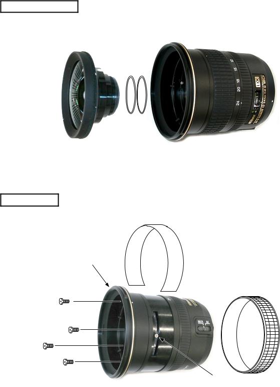
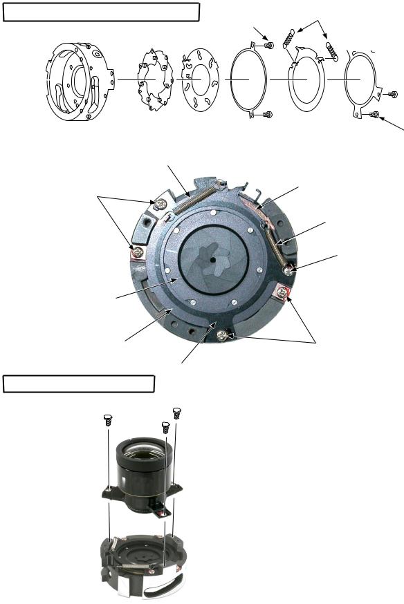
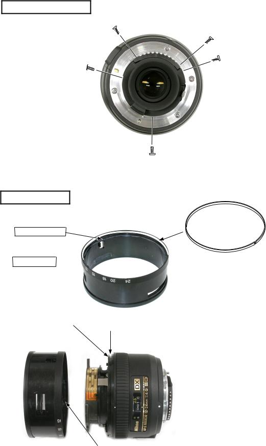
1ST LENS GROUP
#101
FILTER RING
#103
Filter ring
#104×4 |
#35 |
|
#79
Remove the rubber ring (#35).Remove the blindfolding-cover (#103).Unscrew #79.
Take out 4 screws (#104).Remove the filter ring.
- L1 AF-S DX12-24/4G -
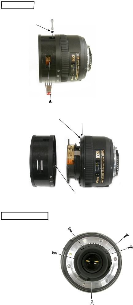
ZOOM RING |
|
#127 |
#87 |
|
B4 |
|
#66 |
|
#22 |
Groove |
|
|
Zoom ring |
|
INC
JAA78451-R.3596.A
Unscrew #87.Unscrew #66.Remove the encoder brush (B4).Remove the zoom ring.
Note The convex 3 parts of the zoom ring are grooved in #22. So remove the zoom ring by turning it to the position where the convex parts detach from the groove.
Convexity
REAR COVER RING
#64×2
#66×3
 Rear cover ring
- L2 AF-S DX12-24/4G -
INC
JAA78451-R.3596.A
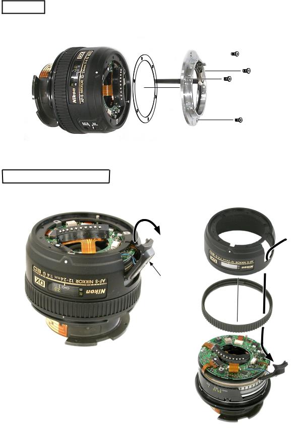
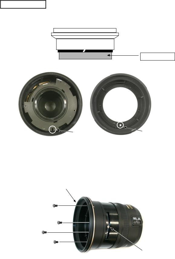
BAYONET
#100 |
#110 |
|
|
|
|
|
|
|
#109×3
INDEX RING, FOCUS RING
Index ring |
Index ring |
|
M/Achange-over
SW
Fig. 1.
Detach the M/Achange-over SW from the index ring by sliding it as shown in Fig. 1.
Remove the index ring.
Remove the focus ring.
Note Pass the M/Achange-over SW through the hole of the index ring as shown in Fig. 2.
Fig. 2.
Focus ring
M/Achange-over
SW
- L3 AF-S DX12-24/4G -

MAIN PCB
Zoom encoder FPC
INC
JAA78451-R.3596.A
Distance encoder FPC
Remove the FPCs (positioned at 4 parts) Main PCB from the connecter.
Unscrew #89.
Remove the main PCB.
 SWM FPC
 #89
#89
MR sensor FPC
SWM UNIT
#90×3
#90×3
#29
SWM unit
- L4 AF-S DX12-24/4G -
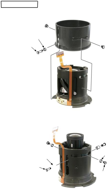
CAM RING UNIT
#72
#77
#97 × 2 #98 × 2 
INC
JAA78451-R.3596.A
#86
#78 × 2
#72 × 2
#84 × 2
- L5 AF-S DX12-24/4G -

Cam ring
1st sliding ring
Can ring
1st sliding ring


 #95×3
#95×3 
 #135×3 #96×3
INC
JAA78451-R.3596.A
Take out the cam ring by turning the 1st sliding ring in the direction indicated by the arrow.
Detach the 2nd and 3rd units from the cam ring.
2nd and 3rd units
- L6 AF-S DX12-24/4G -

INC
JAA78451-R.3596.A
2ND LENS GROUP
#72×2 #84×2
2nd lens group
3RD LENS GROUP
Note If the 3rd lens group is removed, the shaft alignment is necessary after assembling. If the shaft alignment is impossible in your service offices, do not remove the 3rd lens group.
 #68×3
#68×3
3rd lens group
Aperture blade housing
- L7 AF-S DX12-24/4G -
Assembly
APERTURE BLADE HOUSING UNIT
INC
JAA78451-R.3596.A
#59 × 2 |
#80 × 2 |
|


 #59 × 2
Aperture blade housing unit |
B5 × 7 |
#33 |
#52 |
#56 |
#58 |
#60 |
|
|
|
|
|
||
|
#80 |
|
|
|
|
|
|
|
|
|
#52 |
|
|
#59 |
|
|
|
|
|
|
|
|
|
|
|
#80 |
|
|
|
|
|
|
#60 |
|
#33 |
|
|
|
|
|
|
#56 |
|
|
|
|
#59 |
|
|
#58 |
|
|
|
|
|
3RD LENS GROUP |
|
|
|
|
|
|
|
|
#68 × 3 |
|
|
|
|
3rd lens group
Aperture blade housing
- L8 AF-S DX12-24/4G -
2ND LENS GROUP
#34
INC
JAA78451-R.3596.A
Apply the grease (GE-8) to 3 parts of the cam groove and the all-round of #34.
#72×2 #84×2
2nd lens group
1ST SLIDING RING
Grease: GE-8
1st sliding ring
Grease: GE-8
Apply the grease (GE-8) to 5 parts of the cam groove and across stepped parts.Assemble the 1st sliding ring at the below position.
Grease: GE-8
|
Cam ring |
|
#95×3 |
1st sliding ring |
Cam ring |
|
||
#135×3 |
|
|
#96×3 |
|
|
LIMIT PLATE
Limit plate #69×2
Grease: MZ-800S
- L9 AF-S DX12-24/4G -

ZOOM ENCODER FPC
Attach with Super glue
INC
JAA78451-R.3596.A
Attach the FPC along the groove.
 Apply the grease (GE-8) to the cam grooves (3 transversal grooves and 2 longitudinal grooves.).
Apply the grease (GE-8) to 3 inside cam grooves.
Inside cam groove
Do not let the FPC run off downwards.
Align the end of FPC in this position.
CAM RING UNIT
2nd and 3rd group units
Insert the 2nd and 3rd group units into the cam ring in the position as shown in the left.
 Cam ring
Cam ring
Insert the cam ring by aligning it with the 3 guide rollers and 3 notches of #51.
#51
Notch
Guide roller
- L10 AF-S DX12-24/4G -
1st sliding ring
#97×2
#98×2
INC
JAA78451-R.3596.A
Turn the 1st sliding ring in the direction indicated by the arrow.
Make sure that the limit plate is entered in the notches of the 2nd and 3rd group units.
Apply the grease (MZ-800S) to the 1 longitudinal groove and 3 transversal grooves of #86.
#86
#72
#77
#78×2
#72×2
#84×2
- L11 AF-S DX12-24/4G -

INC
JAA78451-R.3596.A
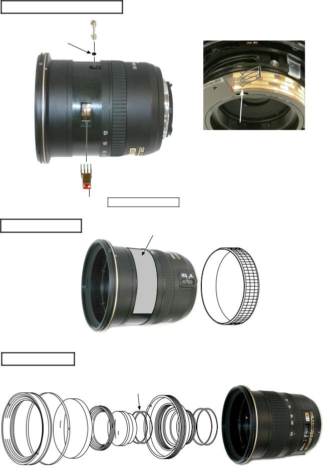
POSITIONADJUSTMENT OF LIMIT PLATE
#69
Limit plate |
Fix the limit plate in the center. |
|
As shown in Fig. 1., assemble #29 and the |
|
bayonet. |
|
The aperture lever (#55) is put intoAof Fig. |
|
2. |
#29 |
#55 |
|
Bayonet
#90×3 
 #109×3
Fig. 1.
Fig. 2.
Turn the zoom to TELE side.
(to the position where the 2nd and 3rd lens units are pushed downward.)
Move the aperture lever slowly in the direction indicated by the arrow, and make sure of being the full aperture when the aperture blades stop.
Make adjustments by changing the position of attaching the limit plate.
After adjusting, apply the Screw Lock to #69.
Remove #29 and the bayonet.
Aperture lever
2nd and 3rd group units
- L12 AF-S DX12-24/4G -
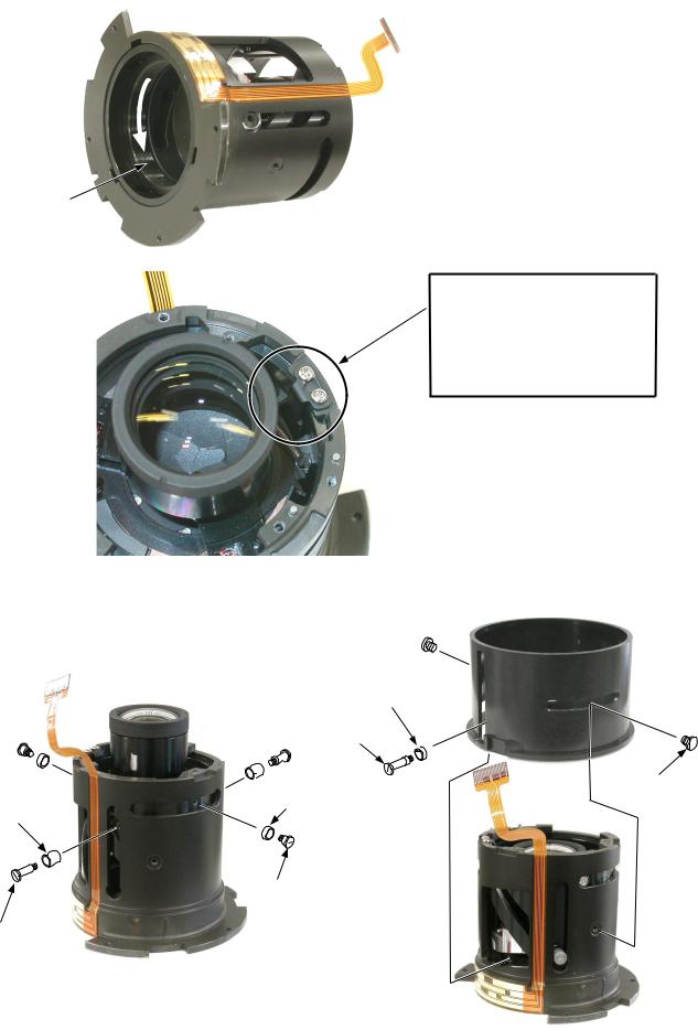
MR HEAD
MR head
MR sensor FPC
SWM unit
INC
JAA78451-R.3596.A
#541 × 2
#534
Attach the head so that it is aligned parallel to the magnetic tape.
Attach the sensor FPC so that it goes alongside the inside groove of the SWM unit.
Magnetic tape
#533
#536
#543
INSPECTIONANDADJUSTMENT FOR THE WAVEFORM OUTPUT FROM MR ENCODER
●In case of disassembling or replacing the MR head, be sure to make adjustments.
1. Equipment and tools to be required
Single output rated voltage power supply: 1 unit With 5.0V and 100mA, applicable to the self-made tool
Oscilloscope: 1 unitSelf-made tool: 1 unit
Note In case of any trouble in continuity between the self-made tool and the contacts of relay FPC, there may be dust, corrosion or oxidation on the contact surface of relay FPC. Be sure to polish the contact surface prior to connect to the self-made tool.
2. Preparation for the measuring lens
Set the SWM unit on which the MR head is already set, the MF ring, the rear fixing tube, and the index ring into the cam ring unit. Then connect to the measuring devices. (Refer to the next page.)
Note: When make checks and adjustments, put a cloth under the lens to avoid any damages to the rear lens.
- L13 AF-S DX12-24/4G -
INC
JAA78451-R.3596.A
#90×3
#90×3
SWM unit
Rear fixing tube
Focus connection key
#86
Insert the focus connection key into the groove of #86.
Index ring
MF ring
Pass this FPC through the hole of the index ring.
- L14 AF-S DX12-24/4G -

INC
Connections
Self-made tool
 Oscilloscope(2ch)
Oscilloscope(1ch)
Power supply(+)
Power supply(-)
JAA78451-R.3596.A
Power supply
Set values
.
(GND)
( )
Self-made tool
Oscilloscope
2ch
How to conduct inspection and adjustment
Make sure that the current and voltage of the connected rated voltage power supply are set values.If they meet the set values, turn on the power.
Set the oscilloscope and drive the focus ring by hand.
Note Since the shape of waveform varies according to the driving speed of focus ring, particularly and properly set Time/Div.
In case of detecting any wider waveform noise, use the filter function.
How to set the filer function in the employment case of Yokogawa-manufactured DL1540
Press the filter button.
Select "Smooth" in the menu on the PC screen.
CH1=20mV |
CH2=20mV |
5ms/div |
AC 10:1 |
AC 10:1 |
|
|
|
NORM 200KS/s |
● Oscilloscope setting |
|
|
V/Div (ch1) |
|
: |
V/Div (ch2) |
|
: |
Coupling |
|
: |
Time/Div |
|
: Sec |
Trigger Mode : |
||
Trigger Coupling |
: |
|
Trigger Source |
|
: |
Trigger Position |
: div |
|
Trigger Type |
: |
|
Trigger Level |
: |
|
INPUT (ch1) |
|
: |
INPUT (ch2) |
|
: |
Standard The amplitude of every pulse/waveform should be 50mV or more.
Note Check the waveform by letting the focus ring to travel from the infinity-end position to the near distance end position and vice versa.
- L15 AF-S DX12-24/4G -
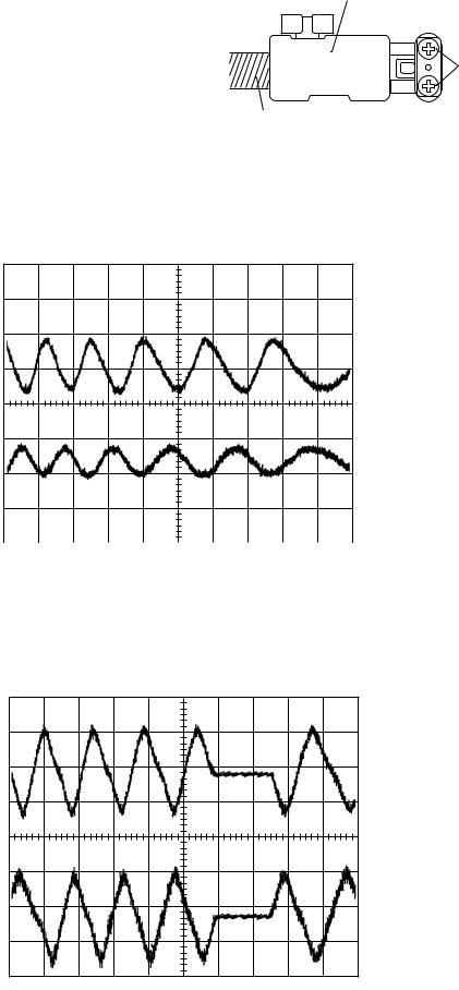
In the case of smaller amplitude, for adjustment, loosen
the two screws #541 and then shift the MR head position
as shown in the right figure.
Note During adjustment, prevent the magnetic tape and MRhead from touching the magnetized driver bit, or the magneticdata may be damaged.
INC
JAA78451-R.3596.A
MR head
541 × 2
Magnetic tape
Reference
● In case the amplitude of either CH1 or CH2 seems smaller, one of the two screws #541 may be loosened.
Then, check the screws. In case the screws are fully tightened, the MR head may be troubled. Then, be sure to
replace the MR head unit B15 and adjust it again.
CH1=20mV |
CH2=20mV |
5ms/div |
AC 10:1 |
AC 10:1 |
|
|
|
NORM 200KS/s |
● In case of a presence of partial drop in the amplitude between the infinity and the near distance, the magnetic datain magnetic tape may be damaged. Then, replace the magnetic tape and adjust it again.
CH1=20mV |
CH2=20mV |
5ms/div |
AC 10:1 |
AC 10:1 |
|
|
|
NORM 200KS/s |
Turn off the rated voltage power supply and remove the SWM unit.
- L16 AF-S DX12-24/4G -

INC
JAA78451-R.3596.A
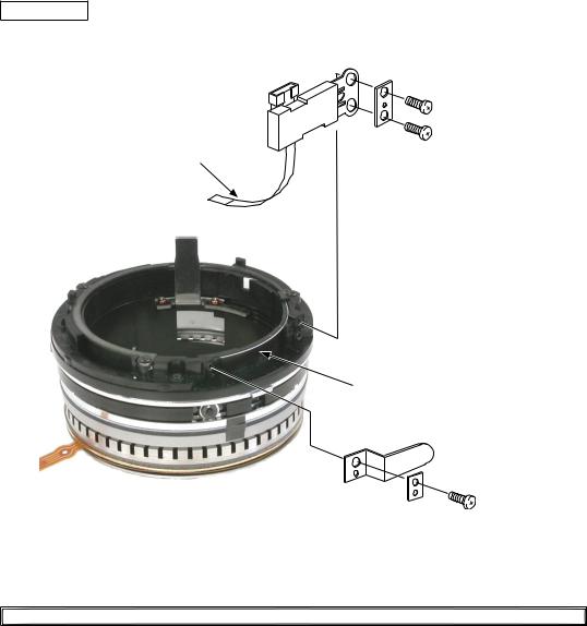
SWM UNIT
 #131×4 #22 #22
#88
Attach #88 to #22, and apply the oil barrier to the overall #88.Build #22 in the SWM unit.Tighten 4 screws (#131 .
SWM
#90×3
SWM unit
#90×3
#29
Focus connecting key
#86
Insert the focus connecting key into the groove of #86.
Pass the circled FPC through the inside of #29.
- L17 AF-S DX12-24/4G -

MAIN PCB
Zoom encoder FPC
INC
JAA78451-R.3596.A
Distance encoder FPC
Attach the main PCB. Main PCB Screw #89.
Connect the FPC (at 4 parts) to the connector.
 SWM FPC
 #89
#89
MR sensor FPC
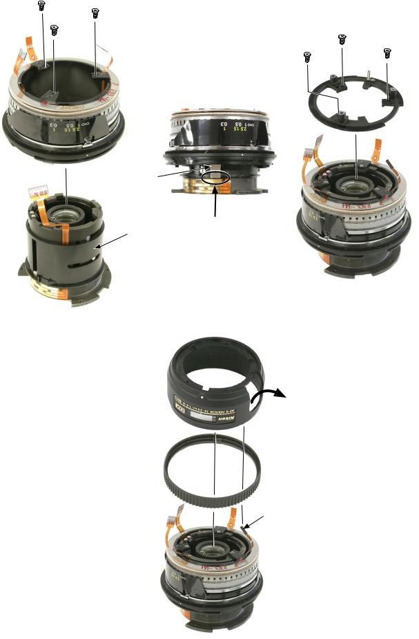
INDEX RING, FOCUS RING |
|
|
|
|
|
|
|
Index ring |
On the sliding surface with focus |
||
|
ring. |
||
|
|
|
|
|
|
Grease: MZ-800S |
|
#75
Focus ring
M/Achange-over
SW
 Projection
Attach #75 to the focus ring, and apply the oil barrier to the overall #75.
Assemble the focus ring by aligning the inside notches (at 3 parts) and the projections of SWM (at 3 parts).
Assemble the index ring by passing the M/Achangeover SW unit through the hole of the index ring.
- L18 AF-S DX12-24/4G -

INC
JAA78451-R.3596.A
Index ring
Slide the M/Achange-over SW and assemble into the index ring.
M/Achange-over SW
BAYONET
#100 |
|
#110 |
|
#55 |
|
||
|
|
|
#109×3
Put the aperture lever (#55 inA of the above.
POSITIONADJUSTMENT OFAPERTURE LEVER
J18004-1
#93×2
Turn the zoom to the TELE side.to the position where the 2nd and 3rd lens units are pushed downward.
Attach the tool (J18004-1) and make sure of the aperture diameter.
Standard: Full aperture
In case it is out of standard, adjust the position of the aperture lever by loosening 2 screws (#93).
After adjusting, fix the 2 screws (#93) with Screw Lock.
Aperture lever
- L19 AF-S DX12-24/4G -
INC
JAA78451-R.3596.A
REAR COVER RING
#64×2
#66×3
 Rear cover ring
ZOOM RING
All-round
Grease: MZ-800S
3 convexities Grease:GE-8 
|
#105 |
|
Zoom ring |
Attach #105 to the zoom ring, and |
|
apply the oil barrier to the overall |
||
|
||
|
#105. |
#22
Zoom ring
Groove
Put the convexities (at 3 parts) inside the zoom ring in the notches (at 3 parts) of #22, to assemble together.
Convexity
- L20 AF-S DX12-24/4G -
INC
JAA78451-R.3596.A
FILTER RING
All-round
Grease: GE-8
Filter ring
Notch |
Convesity (on backside) |
Put the convexity of the fileter ring in the notch of the above, and attach the filter ring with 4 screws (#104).
Filter ring
#104×4
#79
- L21 AF-S DX12-24/4G -
ZOOM ENCODER BRUSH
#87
#127
B4
 #66 Attach with Screw Lock
RUBBER RING
#103
1ST LENS GROUP
#41 |
#102 |
#G1 |
#126 × 2 |
B1 |
|
|
|||
|
|
|
#42 |
|
|
|
|
#G2.3 |
|
INC
JAA78451-R.3596.A
Position to attach the encoder brush
Turn the zoom to the TELE side.
Attach the encoder brush (B4) in the above position and fix it with screw (#66).
After adjusting,fix #66 with the Screw Lock.
#35
#101
● The size of 2 washers (#126) is fixed (0.038mm).
- L22 AF-S DX12-24/4G -

INC
JAA78451-R.3596.A
ADJUSTMENT (DIVISION) OF FOCUS MOVEMENT (T, W)
Fit the infinity ( ∞ ) mark of the focus ring to the index.Fix the aperture lever to make the aperture "full".Read the values of the Wide and Tele sides.Carry out the following calculations.
|
Value of Tele side |
|
Value of Wide side |
|
Adjustment amount (mm) of the 2nd lens group unit washer #101 |
Adjust the thickness of the washer #101 by the value of C calculated in the above. If C is positive, thicken thewasher. If it is negative, thin the washer.
Note When setting the washer #101, put a thin washer between thick washers.
ADJUSTMENT OF BACK FOCUS
Fit the infinity ( ∞ ) mark of the focus ring to the index.Fix the aperture lever to make the aperture "full".Read the value of Wide or Tele side.
Remove the bayonet mount.
Adjust the thickness of the washer #100 by the difference from the standard value. If the difference value ispositive, thicken the washer. If it is negative, thin the washer.
Focal length |
Standard |
|
|
|
|
|
|
|
|
|
|
|
|
|
|
- L23 AF-S DX12-24/4G -
 Loading...