


 Loading...
REPAIIIRMANUAL
IIINDV:2III
1 |
INTRODUCTION........................................... |
3 |
1.1 |
Purpose of the document................................................... |
3 |
1.2 |
Pictograms .......................................................................... |
3 |
2 |
SAFETY ........................................................ |
4 |
2.1 |
Safety warnings .................................................................. |
4 |
2.2 |
Repair warnings .................................................................. |
4 |
2.3 |
EGB ...................................................................................... |
5 |
3 |
COMPONENTS AND FUNCTION ................ |
8 |
3.1 |
Electronic Induction (ELIN) ................................................ |
8 |
3.2 |
Bosch TouchControl......................................................... |
12 |
3.3 |
Siemens TouchControls................................................... |
15 |
3.4 |
Neff TouchControl ............................................................ |
18 |
3.5 |
Balay TouchControl.......................................................... |
21 |
3.6 |
ELIN support ..................................................................... |
23 |
3.7 |
Glass frame ....................................................................... |
25 |
3.8 |
Fan ..................................................................................... |
28 |
3.9 |
NTC .................................................................................... |
29 |
3.10 |
Inductors............................................................................ |
33 |
3.11 |
Connections ...................................................................... |
38 |
3.12 |
Perfect Built in union accessory ..................................... |
43 |
4 |
FAULT DIAGNOSTICS............................... |
47 |
4.1 |
Error codes or warnings sent by the ELIN...................... |
47 |
4.2 |
Error codes or warnings sent by the TouchControl ...... |
53 |
5 |
CHECK AND REPAIR................................ |
58 |
1.1Activation and deactivation of the technical services
program for TouchControl .............................................................. |
58 |
|
5.2 |
Technical Services Program for TouchControl............... |
66 |
5.3 |
NTC sensor checks ........................................................... |
71 |
5.4 |
Fan checks ......................................................................... |
72 |
5.5 |
Coil checks......................................................................... |
72 |
5.6 |
Induction unit checks (ELIN) ............................................ |
73 |
5.7 |
Checks for when the circuit breaker trips ....................... |
74 |
5.8 |
Radio interference ............................................................. |
82 |
5.9 |
Checking the level of supplied power.............................. |
84 |
5.10 |
Checking hob flatness....................................................... |
93 |
5.11 |
Checking standard operation noises............................... |
94 |
5.12 |
Checking pot detection ..................................................... |
95 |
5.13 |
Checking of broken glass ................................................. |
97 |
5.14 |
Cookware for induction and recommendations.............. |
99 |
5.15 |
Disassembly of the TouchControl.................................. |
102 |
5.16 |
Check: low sensitivity on the TouchControl Slider ...... |
103 |
5.17 |
Checking the replacement part is correct ..................... |
104 |
5.18 |
Checking SQ YL-196 TouchControl operation .............. |
109 |
5.19 |
Checking the “foam” ....................................................... |
110 |
5.20 |
Checking perfect built-in accessory joint...................... |
111 |
5.21 |
Checking necessary ventilation: 60/70 cm.................... |
114 |
5.22 |
Installation of flat recess in timber using accessory.... |
116 |
5.23 |
Assembly and disassembly: 2i....................................... |
118 |

5.24 |
Check of residual heat indication.................................. |
120 |
r630005d - 16.10.2008 – Dieter Helmich |
Page 2 of 122 |

1 INTRODUCTION
1.1Purpose of the document
The repair manual provides support for the official technician to help diagnose faults and repair the electrical appliances.
Apart from the repair manual, the technician may also use the following documents:
-Blow-up diagram of parts of the appliance.
-Diagrams
-List of parts
-Associated technical reports on specific occasions
The diagnosis of faults plus their repair should only be carried out by an officially authorised technician.
1.2Pictograms
Warning!
Components sensitive to electrostatic shock:
Respect EGB reference
Sharp edges:
Use protective gloves!
Information or advice
Electrical hazard!
r630005d - 16.10.2008 – Dieter Helmich |
Page 3 of 122 |

2 SAFETY
2.1Safety warnings
Electrical hazard!
Repairs should only be carried out by the manufacturer’s technical staff.
Inadequate repairs can harm the users.
The sheath and framework may be subjected to voltage in case of failure.
The appliance should be disconnected from the mains before dismounting. It contains parts inside that are subjected to high voltage.
Always use a current-breaker switch if it is necessary to conduct lowvoltage tests.
The earth connection should not exceed standardised values. This is of the utmost importance for people’s safety and normal working conditions of the appliance.
Once the appliance has been repaired, it should be subjected to tests
VDE 0701 or the specific regulations that are in force in the country concerned.
The replacement of the power cable can only be carried out by authorised technical staff, using the replacement cable.
Special warnings for induction hobs!
Induction hobs comply with the safety and electromagnetic compatibility regulations currently in force (EN50366). People with fitted pacemakers should abstain from using or repairing such an appliance. The operation of the appliance may interfere with the operation of the pacemaker.
People with hearing aids may experience discomfort.
2.2Repair warnings
Warning!
Never attempt to carry out repairs involving the indiscriminate exchange of component parts.
Proceed in a systematic way, with reference to the technical specifications supplied with the appliance.
The electronic plates should not be repaired, but replaced with original spare parts. Exceptions are indicated in separate documents.
Components sensitive to electrostatic shock:
Respect EGB reference
Sharp edges:
Use protective gloves!
r630005d - 16.10.2008 – Dieter Helmich |
Page 4 of 122 |
2.3EGB
2.3.1Concept
EGB = “Elektrostatisch Gefährdete Bauelemente“ (Electrostatic-
Sensitive Devices)
(Component sensitive to electrostatic shock)
2.3.2Pictogram
Electronic devices with components that are sensitive to electrostatic shock (EGB in German) are marked with the pictogram shown here.
2.3.3General specifications
The use of cutting-edge electronic technology in current electrical appliances guarantees high levels of profitability, protection of the environment, easy handling, operability and safety. Such highperformance technology can only be handled by qualified technicians with specialised knowledge.
All electronic modules and constructive units incorporate elements with a potentially dangerous electrostatic voltage.
2.3.4Dangerous components
Amongst others, these constructive elements are threatened by electrostatic voltage:
!µProcessors
!ICs
!Transistors
!Tiristors
!Triacs
!Diodes
!etc.
2.3.5Causes and effect
The human body can generate electrostatic charges in certain environmental situations. This charge is favoured by dry air and the coating on insulated floors.
People can transfer an electrostatic voltage:
!of up to 35,000 volts when standing on a non-conductive carpet.
!of up to 12,000 volts when standing on a non-conductive PVC floor.
!of up to 1.800 volts when sitting in a padded chair.
The electrostatic voltage in the human body is transferred to electronic devices and components that are sensitive to electrostatic shock by touching them, sometimes resulting in damage depending on the circumstances.
r630005d - 16.10.2008 – Dieter Helmich |
Page 5 of 122 |

Mortal attack!
-component rendered useless
-constructive unit rendered useless
-equipment rendered useless
Light attack!
-damaged
-weakened
-premature failure
2.3.6Indications for components sensitive to electrostatic shock
In all electronic modules and constructive units there are components that are sensitive to electrostatic shock.
In order to protect such components, the following steps should be taken:
1.Read the corresponding label for the modules and constructive units with care.
2.Before touching and measuring any components that are sensitive to electrostatic shock, apply an electrostatic protection system (wristband with earth block).
3.Avoid touching these components with electrostaticallysensitive plastics (plastic sheeting, etc.).
4.Constructive units, modules and plate should be picked up as far as possible without touching the printed circuit boards and connections.
5.Components that are sensitive to electrostatic shock should not be located close to monitors or televisions.
6.For transport purposes, only conductive materials or the original packing should be used.
r630005d - 16.10.2008 – Dieter Helmich |
Page 6 of 122 |

2.3.7Electrostatic protection system
There are several different electrostatic protection systems.
These electrostatic protection systems act to prevent the electrostatic shock from affecting the human body or by shunting the existing electrostatic voltage to earth.
In the electrostatic protection system used at the after-sales customer service, the electrostatic voltage in the body is transferred by means of a wristband and earth block.
For safety reasons, this is not carried out directly but using a combination of elements
The connection with the earthwire conductor or protective conductor should be in perfect condition
Combination of elements with wristband
r630005d - 16.10.2008 – Dieter Helmich
Page 7 of 122
3 COMPONENTS AND FUNCTION
3.1Electronic Induction (ELIN)
There are two types of elin (electronic induction).
!One with its own power supply (“left or main elin”)
!Another one without its own power supply (“right or secondary elin”), which is powered by the main elin.
They are attached to the elin bracket with clips, plus a couple of screws.
They communicate with the TouchControl through the LIN connector.
The TouchControl sends power level orders for each burner and the elin returns the state of the burner (pan recognition, error detection, etc.)
Depending on the type of model there are:
Domino |
1 main elin |
|
2I |
60 cm |
1 main elin |
4I |
60cm |
1 main elin / 1 secondary elin |
4I |
70 cm |
1 main elin / 1 secondary elin |
4I |
80cm |
1 main elin / 1 secondary elin |
3I |
|
1 main elin / 1 secondary elin |
5I |
90cm |
2 main elin / 1 secondary elin |
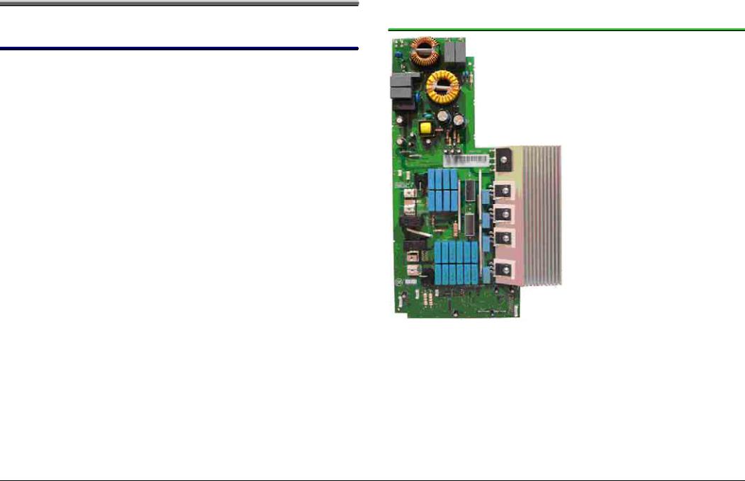
3.1.1ELIN with own power supply (“left Elin”)
r630005d - 16.10.2008 – Dieter Helmich |
Page 8 of 122 |
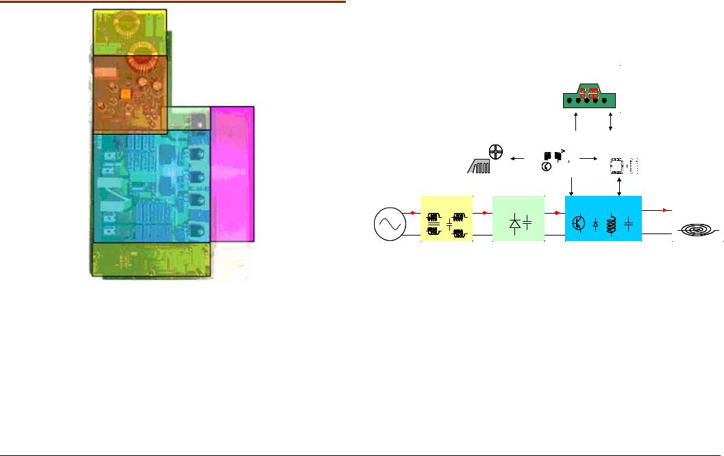
3.1.1.1Components of Elin with own power supply
User Interface |
Cooling |
|
Power Supplier |
|
|
Control |
|||||||||||||||||
|
|
|
|
|
|
|
|
|
|
|
|
|
|
|
|
|
|
|
|
|
|
|
|
|
|
|
|
|
|
|
|
|
|
|
|
|
|
|
|
|
|
|
|
|
|
|
|
|
|
|
|
|
|
|
|
|
|
|
|
|
|
|
|
|
|
|
|
|
|
|
|
|
|
|
|
|
|
|
|
|
|
|
|
|
|
|
|
|
|
|
|
|
|
|
|
|
|
|
|
|
|
|
|
|
|
|
|
|
|
|
|
|
|
|
|
|
|
|
|
|
|
|
|
|
|
|
|
|
|
|
|
|
|
|
|
|
|
|
|
|
|
|
|
|
|
|
|
|
|
|
|
|
|
|
|
|
|
|
|
|
I1 |
EMC Filter |
I2 |
Rectify |
II |
Inverter |
I0 |
Inductor |
|
|||||||
V |
|
V2 |
|
VI |
|
V0 |
|
1- Interference filter (yellow)
2- Power supply (red)
3- Rectificator (light green)
4- Power inverter (blue)
5- Control (green)
6- Cooling element (pink)
r630005d - 16.10.2008 – Dieter Helmich |
Page 9 of 122 |

3.1.2ELIN without own power supply (“right ELIN”)
3.1.2.1Components of elin without own power supply
1- Interference filter (light green)
2- Rectificator (light yellow)
3- Power inverter (blue)
4- Control (green, bottom part)
5- Cooling element (left grey)
r630005d - 16.10.2008 – Dieter Helmich |
Page 10 of 122 |
I |
Filter |
Rectificator |
Inverter |
I0 |
Inductor-pot |
V |
|
VI |
|
V0 |
|
V |
VI |
V0 |
I
I0
25-75 kHz
3.1.3ELIN functions
3.1.3.1Power supply
Elins with their own power supply power the various components of the induction hob (fan, touchControl, elin without its own power supply, etc...)
3.1.3.2Regulation
The elin regulates the power of the inductors by means of the IGBTs
(insulated-gate bipolar transistors) and coordinates the signals given by the user through the control panel with the various induction zones.
3.1.3.3Communication
!The elin returns the state of the burner.
For example, if the pan is not detected, the power selected starts flashing (See pan recognition)
!It indicates the warnings and errors sent by the elin (See errors and warnings)
!It communicates with the touchControl by means of the 4-cable
LIn connector.
r630005d - 16.10.2008 – Dieter Helmich |
Page 11 of 122 |
3.2Bosch TouchControl
3.2.1Bosch dominos
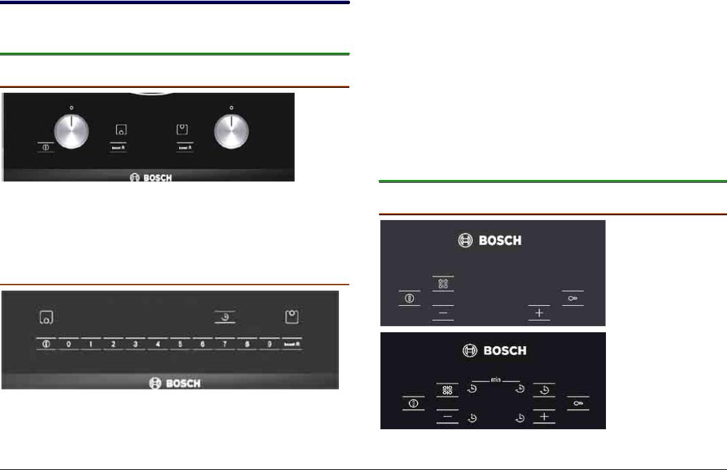
3.2.1.1Control knobs YL-167
!Control knobs
!9 power levels
!Powerboost function
!“On/Off” sensor
3.2.1.2Precise TouchControl YL-199
!Precise TouchControl
!One sensor for each level – intuitive direct access to each level
!9 power levels
!Direct switch off for each cooking zone
!Powerboost function with separate sensor
!“On/Off” sensor
!Timer function
!Residual heat indicator H/h
!Power Management
3.2.2Bosch 60 / 70 / 80 / 90 cm
3.2.2.1 TouchControl Superquattro (SQ) YL-196
r630005d - 16.10.2008 – Dieter Helmich |
Page 12 of 122 |

!One +/- Sensor for each cooking zone
!17 power levels
!Powerboost function after level 9
!“On/Off” sensor
!Timer function depending on model
!Residual heat indicator H/h
!Power management
!Child lock
3.2.2.2+/ - TouchControl Sensor YL-202
! +/- Sensors for each cooking zone
!17 power levels
!Powerboost function after level 9
!Sensor “On”
!Timer function depending on model
!Residual heat indicator H/h
!Power management
!Child lock
3.2.2.3PreciseTouchControl 60 / 70 / 80 / 90 cm YL-180
!One sensor for each level – intuitive direct access to each level
!17 power levels
!Direct switch off for each cooking zone
!Powerboost function with separate sensor
!“On/Off” sensor
!Timer function
!Frying sensor depending on model with 4 levels (low- min-med-max)
!9 Frying sensor programs
!Cooking sensor depending on model with 5 levels.
!9 Cooking sensor programs
!Residual heat indicator H/h
!Power management
r630005d - 16.10.2008 – Dieter Helmich |
Page 13 of 122 |

!Child lock
!Key lock
3.2.2.4 Semi-preciseTouchControl 60 / 70 / 80 / 90 cm YL-180
!One sensor for each level and one +/- for each intermediate level
!17 power levels
!Direct switch off for each cooking zone
!Powerboost function with separate sensor
!“On/Off” sensor
!Timer function
!Frying sensor depending on model with 4 levels (low- min-med-max)
!9 Frying sensor programs
!Residual heat indicator H/h
!Power management
!Child lock
!Key lock
3.2.2.5Metal Touch Control (Precise) YL-205
!One sensor for each level – intuitive direct access to each level
!17 power levels
!Direct switch off for each cooking zone
!Powerboost function with separate sensor
!“On/Off” sensor
!Timer function
!Frying sensor depending on model with 4 levels (lowmin- med-max)
!9 Frying sensor programs
!Cooking sensor depending on model with 5 levels.
!9 Cooking sensor programs
!Residual heat indicator H/h
!Power management
!Child lock
!Key lock
r630005d - 16.10.2008 – Dieter Helmich |
Page 14 of 122 |

3.3Siemens TouchControls
3.3.1Siemens dominos
3.3.1.1Control knobs YL-167
!Control knobs
!9 power levels
!Powerboost function
!“On/Off” sensor
3.3.1.2TouchControl Slider YL-207
!TouchControl Slider – intuitive direct access to each level
!17 power levels
!Direct switch off for each cooking zone
!Powerboost function
!“On/Off” sensor
!Timer function
!Residual heat indicator H/h
!Power Management
3.3.260 / 70 / 80 / 90 cm Siemens
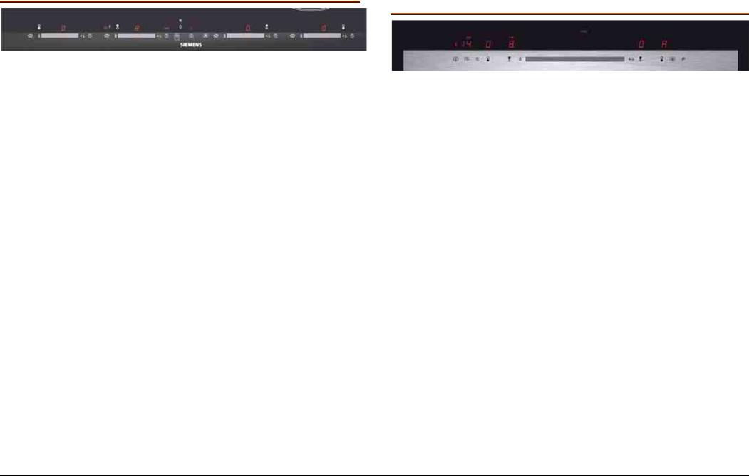
3.3.2.1TouchControl Superquattro (SQ) YL-196
!One +/- sensor for all cooking zones
!17 power levels
r630005d - 16.10.2008 – Dieter Helmich |
Page 15 of 122 |

!Powerboost function after level 9
!“On/Off” sensor
!Timer function depending on model
!Residual heat indicator H/h
!Power management
!Child lock
3.3.2.2 +/ - TouchControl Sensor YL-202
!+/- Sensors for each cooking zone
!17 power levels
!Powerboost function after level 9
!“On” Sensor
!Timer function depending on model
!Residual heat indicator H/h
!Power management
!Child lock
3.3.2.3TouchControl Slider 60 / 70 / 80 / 90 cm YL-190
!TouchControl Slider – intuitive direct access to each level
!17 levels of power
!Direct switch off for each cooking zone
!Powerboost function
!“On/Off” sensor
!Timer function
!Residual heat indicator H/h
!Power Management
!Frying sensor depending on model with 4 levels (low- min-med-max)
!9 Frying sensor programs
!Cooking sensor depending on model with 5 levels.
!9 Cooking sensor programs
!Residual heat indicator H/h
!Power management
!Child lock
!Key lock
r630005d - 16.10.2008 – Dieter Helmich |
Seite 16 von |
122 |
|
3.3.2.4TouchControl multislider 60 / 70 / 80 / 90 cm YL-169/-170
!One Slider touch control for each cooking zone – intuitive direct access to each level
!17 power levels
!Direct switch off for each cooking zone
!Powerboost function
!“On/Off” sensor
!Timer and Egg timer function, one sensor for each cooking zone
!Residual heat indicator H/h
!Keep Warm function
!Power management
!Child lock
!Key lock
3.3.2.5Metal TouchControl (slider) YL-204
!One sensor for each level – intuitive direct access to each level
!17 power levels
!Direct switch off for each cooking zone
!Powerboost function with separate sensor
!“On/Off” sensor
!Timer and Egg timer function
!Frying sensor function depending on model with 4 levels (low-min-med-max)
!9 Frying sensor programs
!Cooking sensor function depending on model with 5 levels.
!9 Cooking sensor programs
!Residual heat indicator H/h
!Power management
!Child lock
!Key lock
r630005d - 16.10.2008 – Dieter Helmich |
Seite 17 von |
122 |
|
3.4Neff TouchControl
3.4.1Neff dominos
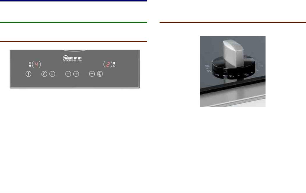
3.4.1.1TouchControl YL-199
!One +/- Sensor for each cooking zone
!9 power levels
!Powerboost function after level 9
!Powerboost function with separate sensor “P”
!“On/Off” sensor
!Residual heat indicator H/h
!Child lock
!Cleaning protection
!Power management
3.4.1.2With controls
The control is oval and just as those of the oven.
r630005d - 16.10.2008 – Dieter Helmich |
Seite 18 von |
122 |
|
3.4.260 / 70 / 80 / 90 cm Neff
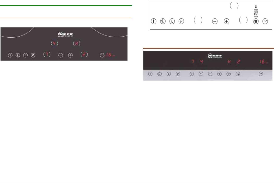
3.4.2.1TouchControl Digiselect YL-188
!One +/- Sensor for all cooking zones
!9 power levels
!Powerboost function after level 9
!Powerboost function with separate sensor “P”
!“On/Off” sensor
!Power management
!Timer function depending of the variant
!Residual heat indicator H/h
!Child Lock or Keep Warm function “L”
!Cleaning protection
!Keep Warm function for each cooking zone
With Frying Sensor function
3.4.2.2TouchControl metalTouch YL-206
!One +/- Sensor for all cooking zones
!9 power levels
!Powerboost function after level 9
!Powerboost function with separate sensor “P”
!Timer function depending of the variant
!Residual heat indicator H/h
!Child Lock or Keep Warm function “L”
!Cleaning protection
!Keep Warm function for each cooking zone
!Power management
The sensors are integrated in a metallic profile.
r630005d - 16.10.2008 – Dieter Helmich |
Page 19 of 122 |
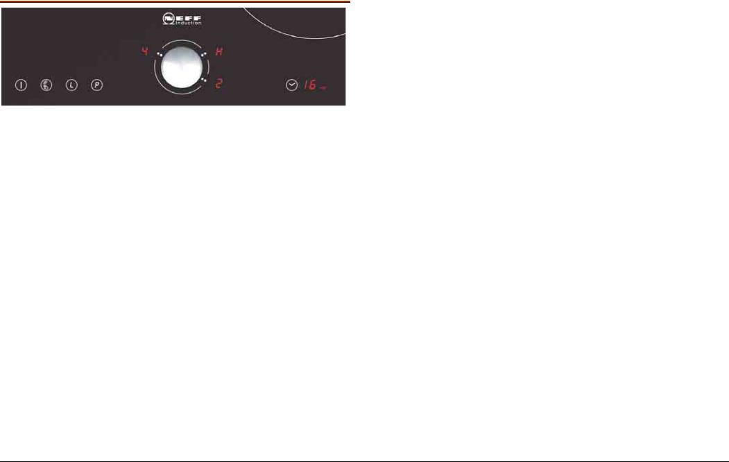
3.4.2.3Touch Control Tippad YL-189
!A only central control device
!Powerboost function after level 9
!Powerboost function with separate sensor “P”
!“On/Off” sensor
!Timer function
!Residual heat indicator H/h
!Power management
!Child Lock “L”
!Key Lock “L”
!Cleaning protection
r630005d - 16.10.2008 – Dieter Helmich |
Page 20 of 122 |
3.5Balay TouchControl
3.5.1Balay dominos
3.5.1.1TouchControl YL-213
!One +/- sensor for each cooking zone
!9 power levels
!Powerboost function after level 9
!Powerboost function with separate sensor
!“On/Off” sensor
!Residual heat indicators H/h
!Child lock
3.5.2Balay 60 / 70 / 80 / 90 cm
3.5.2.1TouchControl Superquattro (SQ) YL-196
!One +/- sensor for each cooking zone
!9 power levels
!Powerboost function after level 9
!“On/Off” sensor
!Timer function depending on model
!Residual heat indicator H/h
!Child lock
r630005d - 16.10.2008 – Dieter Helmich |
Page 21 of 122 |

3.5.2.2 TouchControl Básico+ línea de texto YL-197
It has been cancelled.
!+/- sensors for each cooking zone
!9 power levels
!Powerboost function after level 9
!“On” sensor
!Timer function depending on model
!Residual heat indicator H/h
!Power management
!Child lock
!
3.5.2.3Touch Control Metal Balay
!+/- sensors for each cooking zone
!9 power levels
!Powerboost function after level 9
!“On/Off” sensor
!Timer function
!Frying sensor depending on model with 4 levels (lowmin- med-max)
!9 Frying sensor programs
!Residual heat indicator H/h
!Power management
!Child lock
!Key lock
r630005d - 16.10.2008 – Dieter Helmich |
Page 22 of 122 |

3.6ELIN support
In IH4 (previous project) there was a plastic support without a metal frame.
In the new IH5 project there are two types of support:
!ELIN support 1
!ELIN support 2
!Along with a metal frame, which makes it possible to insert the turrets for the cooking sensor and two more relay modules.
3.6.1ELIN support 2 for 60-70 cm hobs
3.6.2 ELIN support 1 for dominos and combinations
r630005d - 16.10.2008 – Dieter Helmich |
Page 23 of 122 |

3.6.390cm hob
3.6.4 90*35 cm panoramic hob
A- ELIN support 1
A- ELIN support 1
B- ELIN support 2
r630005d - 16.10.2008 – Dieter Helmich |
Page 24 of 122 |

3.7Glass frame
3.7.1Characteristics
The inner framework of the glass frame units consists of 4 frames stuck together.
This design improves the tension that might be created.
The hermetic seal has been replaced by foam, which is fitted by robot.
Old seal
New seal = foam
There are greater advantages to be obtained with foam as opposed to using the hermetic seal:
!Automatically constant thickness
!Site of application is controlled
!Average flatness is reduced by 0.2 mm.
3.7.2Types
We have different sizes and styles for glass frame units. Sizes:
30 cm; 40 cm; 60 cm; 70 cm; 80 cm and 90 cm.
r630005d - 16.10.2008 – Dieter Helmich |
Page 25 of 122 |

Styles
The various styles differ with respect to outer trim, colour of the glass and / or type of mounting, apart from the way the model can be recognised.
Black vitroceramic glass
Metal look vitroceramic glass
White vitroceramic glass
3.7.3Markings on glass
In the models for Balay and Lynx there is a label at the top on the right with the complete model without KI printed on it.
The other models only have the supplier’s number, at the top on the left, enabling us to find out what model it is.
This number is not easy to see. See photo below.
r630005d - 16.10.2008 – Dieter Helmich |
Seite 26 von |
122 |
|

All replacement glass frames will be supplied like this. However, they will have a sticker to remind the people handling them, printed with the following warning:
3.7.4Replacing glass frame for basic units
Warning!
The basic units have trim all around the edge of the glass.
Until recently, the outer metallic trim was completely stuck to the glass with silicon.
Now, although they will be supplied together, they will not be stuck with silicon but with foam, which only keeps the trim in place.
Thus, special care should be taken when handling the replacement glass frame, since it might fall and cause injury should the glass fall on top of us.
r630005d - 16.10.2008 – Dieter Helmich |
Seite 27 von |
122 |
|

3.8Fan
3.8.1Characteristics and assembly
The fan used operates on direct current (without dynamo brushes) and contains electronic components.
It is connected to the ELIN plate by means of a 3-wire connection with some of the ends soldered to the fan’s circuit board
+24V
GND = earth
TACHO = tachograph
It is attached by means of clips (dominos and 2I). In other models it is attached to a bracket, which is screwed into place.
1.1.2 Function
To cool the electronic components.
Warning!
Between the content of the housing and the entrance of the fan there should be a gap of at least 2 cm.
Do not keep small objects and papers in the box, since these could be absorbed by the fan and reduce the cooling effect, or damage the fan.
r630005d - 16.10.2008 – Dieter Helmich |
Seite 28 von |
122 |
|

3.9NTC
3.9.1Types
There are two types of NTCs.
!NTCs for the inductors.
!NTCs for the electronic module (ELIN)
3.9.2Characteristics and assembly
3.9.2.1NTCs for the inductors
In both IH4-I (previous project) and IH5-I (current project) the NTCs measure the temperature directly on top of the glass.
The difference lies in the way the NTC is mounted in the inductor and the fact that they have polarity (i.e. 3 channels for the frying function NTC).
For mounting purposes, a silicon support bracket is used instead of
a metal spring. This reduces the time taken to assemble the Photo of NTC and cross section of new IH5-I project component.
The external NTC has a 3-wire connector and controls the frying sensor function.
They are both interchangeable and have a different code number
(internal 2-wire NTC connector and external 3-wire NTC connector) and can be supplied as spare parts.
r630005d - 16.10.2008 – Dieter Helmich |
Page 29 of 122 |

IH4-I
r630005d - 16.10.2008 – Dieter Helmich |
Seite 30 von |
122 |
|
Loading...