


 Loading...
PROFESSIONAL DIGITAL TWO-WAY RADIO
MOTOTRBO™
DP4400/DP4401
NON-DISPLAY PORTABLE
USER GUIDE
EN DE FR IT ES TU PL RU AR

Contents
This User Guide contains all the information you need to use the MOTOTRBO Series Portables.
Important Safety Information . . . . . . . . . . . . . . . . . iv
Product Safety and RF Exposure Compliance . . .iv
Software Version . . . . . . . . . . . . . . . . . . . . . . . . . . . iv Computer Software Copyrights . . . . . . . . . . . . . . . . v Handling Precautions . . . . . . . . . . . . . . . . . . . . . . . vi
Getting Started . . . . . . . . . . . . . . . . . . . . . . . . . . . . . . 1
How to Use This Guide . . . . . . . . . . . . . . . . . . . . . . . 1 What Your Dealer/System Administrator
Can Tell You . . . . . . . . . . . . . . . . . . . . . . . . . . . . . . 1
Preparing Your Radio for Use . . . . . . . . . . . . . . . . . . 2
Charging the Battery . . . . . . . . . . . . . . . . . . . . . . . . . 2 Attaching the Battery . . . . . . . . . . . . . . . . . . . . . . . . . 3 Attaching the Antenna . . . . . . . . . . . . . . . . . . . . . . . . 3 Attaching the Belt Clip . . . . . . . . . . . . . . . . . . . . . . . . 4 Attaching the Universal Connector Cover
(Dust Cover) . . . . . . . . . . . . . . . . . . . . . . . . . . . . . . 4 Powering Up the Radio . . . . . . . . . . . . . . . . . . . . . . . 5 Adjusting the Volume . . . . . . . . . . . . . . . . . . . . . . . . 5
Identifying Radio Controls . . . . . . . . . . . . . . . . |
. . . . 6 |
Radio Controls . . . . . . . . . . . . . . . . . . . . . . . . . . |
. . . 6 |
Programmable Buttons . . . . . . . . . . . . . . . . . . . . |
. . . 7 |
Assignable Radio Functions . . . . . . . . . . . . . . |
. . . 7 |
Assignable Settings or Utility Functions . . . . . . |
. . . 8 |
Push-To-Talk (PTT) Button . . . . . . . . . . . . . . . . . |
. . . 8 |
Switching Between Conventional Analog and |
|
Digital Mode . . . . . . . . . . . . . . . . . . . . . . . . . . . . |
. . . 9 |
IP Site Connect . . . . . . . . . . . . . . . . . . . . . . . . . . |
. . 10 |
Capacity Plus . . . . . . . . . . . . . . . . . . . . . . . . . . . |
. . 10 |
Linked Capacity Plus . . . . . . . . . . . . . . . . . . . . . |
. . 11 |
Identifying Status Indicators . . . . . . . . . . . . . . . . |
. . 12 |
LED Indicator . . . . . . . . . . . . . . . . . . . . . . . . . . . |
. . 12 |
Indicator Tones . . . . . . . . . . . . . . . . . . . . . . . . . . |
. . 13 |
Audio Tones . . . . . . . . . . . . . . . . . . . . . . . . . . . . |
. . 13 |
Receiving and Making Calls . . . . . . . . . . . . . . . . |
. . 14 |
Selecting a Zone . . . . . . . . . . . . . . . . . . . . . . . . . |
. . 14 |
Selecting a Channel . . . . . . . . . . . . . . . . . . . . . . |
. . 14 |
Receiving and Responding to a Radio Call . . . . |
. . 15 |
Receiving and Responding to a Group Call . . . |
. . 15 |
Receiving and Responding to a Private Call |
. . . 16 |
Receiving and Responding to a Selective Call |
. . 17 |
Receiving an All Call . . . . . . . . . . . . . . . . . . . . |
. . 17 |
Contents
i
English

Contents
ii
Making a Radio Call . . . . . . . . . . . . . . . . . . . . . . . . 18
Making a Call with the Channel Selector Knob . . |
18 |
Making a Group Call . . . . . . . . . . . . . . . . . . . . |
18 |
Making a Private Call . . . . . . . . . . . . . . . . . . . |
19 |
Making a Selective Call . . . . . . . . . . . . . . . . . |
19 |
Making an All Call . . . . . . . . . . . . . . . . . . . . . . |
20 |
Stopping a Radio Call . . . . . . . . . . . . . . . . . . . . . . |
21 |
Talkaround . . . . . . . . . . . . . . . . . . . . . . . . . . . . . . . 21 Monitoring Features . . . . . . . . . . . . . . . . . . . . . . . . 22 Monitoring a Channel . . . . . . . . . . . . . . . . . . . . . 22 Permanent Monitor . . . . . . . . . . . . . . . . . . . . . . . 22
Advanced Features . . . . . . . . . . . . . . . . . . . . . . . . . 23
Scan Lists . . . . . . . . . . . . . . . . . . . . . . . . . . . . . . . . 23 Scan . . . . . . . . . . . . . . . . . . . . . . . . . . . . . . . . . . . . 24 Starting and Stopping Scan . . . . . . . . . . . . . . . . 24 Responding to a Transmission During a Scan . . 24 Deleting a Nuisance Channel . . . . . . . . . . . . . . . 25 Restoring a Nuisance Channel . . . . . . . . . . . . . . 25 Vote Scan . . . . . . . . . . . . . . . . . . . . . . . . . . . . . . . . 25 Call Indicator Settings . . . . . . . . . . . . . . . . . . . . . . 26 Escalating Alarm Tone Volume . . . . . . . . . . . . . . 26 Call Alert Operation . . . . . . . . . . . . . . . . . . . . . . . . 26 Receiving and Responding to a Call Alert . . . . . 26
Making a Call Alert with the
One Touch Access Button . . . . . . . . . . . . . . . . . 26
Emergency Operation . . . . . . . . . . . . . . . . . . . . . . 27 Sending an Emergency Alarm . . . . . . . . . . . . . . 27 Sending an Emergency Alarm with Call . . . . . . . 28 Sending an Emergency Alarm with Voice to
Follow . . . . . . . . . . . . . . . . . . . . . . . . . . . . . . . . . 28 Reinitiating an Emergency Mode . . . . . . . . . . . . 30 Exiting an Emergency Mode . . . . . . . . . . . . . . . . 30 Text Messaging Features . . . . . . . . . . . . . . . . . . . 30 Sending a Quick Text Message . . . . . . . . . . . . . 30 Privacy . . . . . . . . . . . . . . . . . . . . . . . . . . . . . . . . . 31 Multi-Site Controls . . . . . . . . . . . . . . . . . . . . . . . . . 32 Starting an Automatic Site Search . . . . . . . . . . . 32 Stopping an Automatic Site Search . . . . . . . . . . 32 Starting a Manual Site Search . . . . . . . . . . . . . . 32 Lone Worker . . . . . . . . . . . . . . . . . . . . . . . . . . . . . . 33 Password Lock Features . . . . . . . . . . . . . . . . . . . . 33 Accessing the Radio from Password . . . . . . . . . 33 Unlocking the Radio from Locked State . . . . . . . 34 Bluetooth . . . . . . . . . . . . . . . . . . . . . . . . . . . . . . . . 34 Finding and Connecting to a Bluetooth Device . . 35 Disconnecting from a Bluetooth Device . . . . . . . 35 Switching Audio Route . . . . . . . . . . . . . . . . . . . . 35 Utilities . . . . . . . . . . . . . . . . . . . . . . . . . . . . . . . . . . 36 Setting the Squelch Level . . . . . . . . . . . . . . . . . 36 Setting the Power Level . . . . . . . . . . . . . . . . . . . 36
English

Turning the Option Board Feature(s) On or Off . . 36 Turning the Voice Operating Transmission (VOX) Feature On or Off . . . . . . . . . . . . . . . . . . . . . . . . . 36 Turning Radio Tones/Alerts On or Off . . . . . . . . . 37 Checking the Battery Strength . . . . . . . . . . . . . . . 37 Voice Announcement . . . . . . . . . . . . . . . . . . . . . . 37 Intelligent Audio . . . . . . . . . . . . . . . . . . . . . . . . . . 38 GPS . . . . . . . . . . . . . . . . . . . . . . . . . . . . . . . . . . . 38
Batteries and Chargers Warranty . . . . . . . . . . . . . . 39 Limited Warranty . . . . . . . . . . . . . . . . . . . . . . . . . . . 40
Contents
iii
English

Important Safety Information
Product Safety and RF Exposure Compliance
Before using this product, read the operating instructions for safe usage contained in the Product Safety and RF Exposure booklet enclosed with your radio.
Information |
ATTENTION! |
|
|
||
|
This radio is restricted to occupational use only to |
|
|
satisfy FCC/ICNIRP RF energy exposure |
|
Safety |
requirements. Before using this product, read the RF |
|
energy awareness information and operating instructions |
||
|
||
|
in the Product Safety and RF Exposure booklet enclosed |
|
|
with your radio (Motorola Publication part number |
|
Important |
6864117B25) to ensure compliance with RF energy |
|
exposure limits. |
||
|
||
|
For a list of Motorola-approved antennas, batteries, and |
|
|
other accessories, visit the following website: |
|
|
http://www.motorolasolutions.com |
iv
Software Version
All the features described in the following sections are supported by the radio's software version R02.04.00.
Please check with your dealer or system administrator for more details of all the features supported.
English

Computer Software Copyrights
The Motorola products described in this manual may include copyrighted Motorola computer programs stored in semiconductor memories or other media. Laws in the United States and other countries preserve for Motorola certain exclusive rights for copyrighted computer programs including, but not limited to, the exclusive right to copy or reproduce in any form the copyrighted computer program. Accordingly, any copyrighted Motorola computer programs contained in the Motorola products described in this manual may not be copied, reproduced, modified, reverse-engineered, or distributed in any manner without the express written permission of Motorola. Furthermore, the purchase of Motorola products shall not be deemed to grant either directly or by implication, estoppel, or otherwise, any license under the copyrights, patents or patent applications of Motorola, except for the normal non-exclusive license to use that arises by operation of law in the sale of a product.
The AMBE+2TM voice coding Technology embodied in this product is protected by intellectual property rights including patent rights, copyrights and trade secrets of Digital Voice Systems, Inc.
This voice coding Technology is licensed solely for use within this Communications Equipment. The user of this Technology is explicitly prohibited from attempting to decompile, reverse engineer, or disassemble the Object Code, or in any other way convert the Object Code into a human-readable form.
U.S. Pat. Nos. #5,870,405, #5,826,222, #5,754,974, #5,701,390, #5,715,365, #5,649,050, #5,630,011, #5,581,656, #5,517,511, #5,491,772, #5,247,579, #5,226,084 and #5,195,166.
Copyrights Software Computer
v
English

Handling Precautions
The MOTOTRBO Series Digital Portable radio meets IP57 specifications, allowing the radio to withstand adverse field conditions such as being submersed in water.
|
• |
If the radio has been submersed in water, shake the |
|
|
radio well to remove any water that may be trapped |
|
|
inside the speaker grille and microphone port. Trapped |
|
|
water could cause decreased audio performance. |
|
• |
If the radio’s battery contact area has been exposed to |
Precautions |
• |
water, clean and dry battery contacts on both the radio |
To clean the exterior surfaces of the radio, use a diluted |
||
|
|
and the battery before attaching the battery to the |
|
|
radio. The residual water could short-circuit the radio. |
|
• |
If the radio has been submersed in a corrosive |
|
|
substance (e.g. saltwater), rinse the radio and battery |
|
|
in fresh water then dry the radio and battery. |
Handling |
|
solution of mild dishwashing detergent and fresh water |
|
(i.e. one teaspoon of detergent to one gallon of water). |
|
|
|
vi
•Never poke the vent (hole) located on the radio chassis below the battery contact. This vent allows for pressure equalization in the radio. Doing so may create a leak path into the radio and the radio’s submersibility may be lost.
•Never obstruct or cover the vent, even with a label.
•Ensure that no oily substances come in contact with the vent.
•The radio with antenna attached properly is designed to be submersible to a maximum depth of 1 meter (3.28 feet) and a maximum submersion time of 30 minutes. Exceeding either maximum limit or use without antenna may result in damage to the radio.
•When cleaning the radio, do not use a high pressure jet spray on the radio as this will exceed the 1 meter depth pressure and may cause water to leak into the radio.
Do not disassemble the radio. This could damage radio seals and result in leak paths into the radio. Radio maintenance should only be done in service depot that is equipped to test and replace the seal on the radio.
English

Getting Started
Take a moment to review the following:
How to Use This Guide . . . . . . . . . . . . . . . . . . . . . . . . . page 1
What Your Dealer/System Administrator
Can Tell You. . . . . . . . . . . . . . . . . . . . . . . . . . . . . . . . page 1
 How to Use This Guide
This User Guide covers the basic operation of the MOTOTRBO Non-Display Portables.
However, your dealer or system administrator may have customized your radio for your specific needs. Check with your dealer or system administrator for more information.
Throughout this publication, the icons below are used to indicate features supported in either the conventional Analog
mode or conventional Digital mode:
Indicates a conventional Analog Mode-Only feature.
Indicates a conventional Digital Mode-Only feature.
For features that are available in both Analog and Digital modes, no icon is shown.
For features that are available in a conventional multi-site mode, see IP Site Connect on page 10 for more information.
Selected features are also available on the single-site trunking mode, Capacity Plus. See Capacity Plus on page 10 for more information.
Selected features are also available in the multi-site trunking mode, Linked Capacity Plus. See Linked Capacity Plus on page 11 for more information.
 What Your Dealer/System Administrator
Can Tell You
You can consult your dealer or system administrator about the following:
•Is your radio programmed with any preset conventional channels?
•Which buttons have been programmed to access other features?
•What optional accessories may suit your needs?
•What are the best radio usage practices for effective communication?
•What maintenance procedures will help promote longer radio life?
Started Getting
1
English

Preparing Your Radio for Use
2
Preparing Your Radio for Use
Assemble your radio by following these steps:
Charging the Battery . . . . . . . . . . . . . . . . . . . . . . . . . . . page 2 Attaching the Battery. . . . . . . . . . . . . . . . . . . . . . . . . . . page 3 Attaching the Antenna. . . . . . . . . . . . . . . . . . . . . . . . . . page 3 Attaching the Belt Clip. . . . . . . . . . . . . . . . . . . . . . . . . . page 4
Attaching the Universal Connector
Cover (Dust Cover) . . . . . . . . . . . . . . . . . . . . . . . . . . page 4 Powering Up the Radio . . . . . . . . . . . . . . . . . . . . . . . . . page 5 Adjusting the Volume . . . . . . . . . . . . . . . . . . . . . . . . . . page 5
 Charging the Battery
For best performance, your radio is powered by a Motorola-approved Nickel Metal-Hydride (NiMH) or Lithium-Ion (Li-lon) battery. To avoid damage and comply with warranty terms, charge the battery using a Motorola charger exactly as described in the charger user guide.
Charge a new battery 14 to 16 hours before initial use for best performance.
IMPORTANT: ALWAYS charge your IMPRES battery with an IMPRES charger for optimized battery life and valuable battery data. IMPRES batteries charged exclusively with IMPRES chargers receive a 6-month capacity warranty extension over the standard Motorola Premium battery warranty duration.
English

 Attaching the Battery
Align the battery with the rails on the back of the radio. Press the battery firmly, and slide upward until the latch snaps into place. Slide battery latch into lock position.
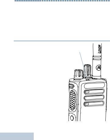
 Attaching the Antenna
With the radio turned off, set the antenna in its receptacle and turn clockwise.
To remove the antenna, turn the antenna counterclockwise.
If antenna needs to be replaced, ensure that only MOTOTRBO antennas are used. Neglecting this will damage your radio.
To remove the battery, turn the radio off. Move the battery latch into unlock position and hold, and slide the battery down
and off the rails.
Battery
Latch
Use for Radio Your Preparing
3
English


 Attaching the Belt Clip
Align the grooves on the clip with those on the battery and press downward until you hear a click.
Use |
To remove the clip, press the |
|
belt clip tab away from the |
||
|
||
for |
battery using a key. Then |
|
slide the clip upward and |
||
|
||
Preparing Your Radio |
away from the radio. |
|
|
4
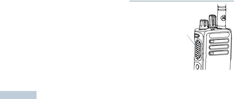
 Attaching the Universal Connector Cover
(Dust Cover)
The universal connector is located on the antenna side of the radio. It is used to connect MOTOTRBO accessories to the radio.
|
Insert the hooked end of the |
|
cover into the slots above the |
|
universal connector. Press |
|
downward on the cover to |
Universal |
seat the lower tab properly |
Connector |
into the RF connector. |
|
Turn the thumbscrew |
|
clockwise to secure the |
|
connector cover to the radio. |
To remove the universal connector cover, press down
on the cover and turn the thumbscrew counterclockwise.
Replace the dust cover when the universal connector is not in use.
English

 Powering Up the Radio
Rotate the On/Off/Volume Control Knob clockwise until you hear a click. The LED lights up solid green.
A brief tone sounds, indicating that the power up test is successful.
NOTE: There is no power up tone if the radio tones/alerts function is disabled (see
Turning Radio Tones/Alerts On or Off on page 37).
If your radio does not power up, check your battery. Make sure that it is charged and properly attached. If your radio still does not power up, contact your dealer.
To turn off the radio, rotate this knob counterclockwise until you hear a click.

 Adjusting the Volume
To increase the volume, turn the On/Off/Volume Control Knob |
forRadioYourPreparing |
|
clockwise. |
||
|
||
To decrease the volume, turn this knob counterclockwise. |
Use |
|
|
NOTE: Your radio can be programmed to have a minimum volume offset where the volume level cannot be turned past the programmed minimum volume. Check with your dealer or system administrator for more information.
5
English

Identifying Radio Controls
6
Identifying Radio Controls
Take a moment to review the following:
Radio Controls . . . . . . . . . . . . . . . . . . . . . . . . . . . . . . . page 6 Programmable Buttons . . . . . . . . . . . . . . . . . . . . . . . . . page 7 Push-To-Talk (PTT) Button . . . . . . . . . . . . . . . . . . . . . . page 8
Switching Between Conventional Analog and
Digital Mode. . . . . . . . . . . . . . . . . . . . . . . . . . . . . . . . page 9 IP Site Connect . . . . . . . . . . . . . . . . . . . . . . . . . . . . . . page 10 Capacity Plus . . . . . . . . . . . . . . . . . . . . . . . . . . . . . . . page 10 Linked Capacity Plus. . . . . . . . . . . . . . . . . . . . . . . . . . page 11
 Radio Controls
1Channel Selector Knob
2On/Off/Volume Control Knob
3LED Indicator
4Side Button 1*
5Push-to-Talk (PTT) Button
6Side Button 2*
7Side Button 3*
8Microphone
1 |
12 |
2 |
11 |
3 |
10 |
|
|
4 |
9 |
5 |
|
8
6
7
9 Speaker
10Universal Connector for Accessories
11Emergency Button*
12Antenna
*These buttons are programmable.
English

 Programmable Buttons
Your dealer can program the programmable buttons as shortcuts to radio functions or preset channels/groups depending on the duration of a button press:
•Short press – Pressing and releasing rapidly.
•Long press – Pressing and holding for the programmed duration.
•Hold down – Keeping the button pressed.
NOTE: The programmed duration of a button press is applicable for all assignable radio/utility functions or settings. See Emergency Operation on page 27 for more information on the programmed duration of the
Emergency button.
Assignable Radio Functions
BluetoothTM Audio Switch – Toggles audio routing between internal radio speaker and external Bluetooth-enabled accessory.
Bluetooth Connect – Initiates a Bluetooth find-and-connect operation.
Bluetooth Disconnect – Terminates all existing Bluetooth connections between your radio and any Bluetooth-enabled devices.
Call Forwarding – Toggles Call Forwarding on or off.
Voice Announcement for Channel – Plays zone and channel announcement voice messages for the current channel. This function is unavailable when Voice Announcement is disabled.
Emergency – Depending on the programming, initiates or cancels an emergency alarm or call.
Intelligent Audio On/Off – Toggles Intelligent Audio on or off.
Manual Site Roam*‡  – Starts the manual site search.
Mic AGC On/Off – Toggles the internal microphone automatic gain control (AGC) on or off. Not applicable during a Bluetooth session.
Monitor – Monitors a selected channel for activity.
Nuisance Channel Delete*‡ – Temporarily removes an unwanted channel, except for the Selected Channel, from the scan list. The Selected Channel refers to the user’s selected zone/channel combination from which scan is initiated.
One Touch Access  – Directly initiates a predefined Private or Group Call, a Call Alert or a Quick Text message.
Option Board Feature – Toggles option board feature(s) on or off for option board-enabled channels.
* Not applicable in Capacity Plus
‡ Not applicable in Linked Capacity Plus
Controls Radio Identifying
7
English
Identifying Radio Controls
8
Permanent Monitor*‡– Monitors a selected channel for all radio traffic until function is disabled.
Privacy  – Toggles privacy on or off.
Repeater/Talkaround*‡ – Toggles between using a repeater and communicating directly with another radio.
Scan*‡ – Toggles scan on or off.
Site Lock On/Off*  – Toggles the automatic site roam on or off.
Telemetry Control  – Controls the Output Pin on a local or remote radio.
Transmit Interrupt Remote Dekey  – Stops an ongoing interruptible call to free the channel.
Voice Announcement On/Off – Toggles Voice Announcement on or off.
Voice Operating Transmission (VOX) – Toggles VOX on or off.
Zone – Allows selection from a list of zones.
Battery Strength – Indicates battery strength via the LED Indicator.
* Not applicable in Capacity Plus
‡ Not applicable in Linked Capacity Plus
Assignable Settings or Utility Functions
All Tones/Alerts – Toggles all tones and alerts on or off.
Power Level – Toggles transmit power level between high and low.
Squelch  – Toggles squelch level between tight and normal.
 Push-To-Talk (PTT) Button
The PTT button on the side of the radio serves two basic purposes:
• While a call is in |
|
progress, the PTT |
PTT Button |
button allows the radio |
|
to transmit to other |
|
radios in the call. |
|
Press and hold down |
|
PTT button to talk. |
|
Release the PTT |
|
button to listen. |
|
The microphone is |
|
activated when the PTT button is pressed.
English

•While a call is not in progress, the PTT button is used to make a new call (see Making a Radio Call on page 18).
Depending on programming, if the Talk Permit Tone or the PTT
Sidetone  is enabled, wait until the short alert tone ends before talking.
During a call, if the Channel Free Indication feature is enabled on your radio (programmed by your dealer), you hear a short alert tone the moment the target radio (the radio that is receiving your call) releases the PTT button, indicating the channel is free for you to respond.
You will also hear a continuous talk prohibit tone, if your call is interrupted, indicating that you should release the PTT button, for example when the radio receives an Emergency Call.
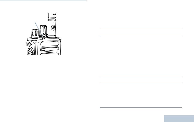
 Switching Between Conventional Analog
and Digital Mode
Each channel in your radio
can be configured as a Channel Selector Knob
conventional analog or conventional digital channel. Use the Channel Selector Knob to switch between an analog or a digital channel.
When switching from digital to analog mode, certain features are unavailable.
Your radio also has features available in both analog and digital mode. However, the minor differences in the way each feature works does NOT affect the performance of your radio.
NOTE: Your radio also switches between digital and analog modes during a dual mode scan (see Scan on page 24).
Controls Radio Identifying
9
English

Identifying Radio Controls
10
 IP Site Connect
This feature allows your radio to extend conventional communication beyond the reach of a single site, by connecting to different available sites which are connected via an Internet Protocol (IP) network.
When the radio moves out of range from one site and into the range of another, it connects to the new site's repeater to send or receive calls/data transmissions. Depending on your settings, this is done automatically or manually.
If the radio is set to do this automatically, it scans through all available sites when the signal from the current site is weak or when the radio is unable to detect any signal from the current site. It then locks on to the repeater with the strongest Received Signal Strength Indicator (RSSI) value.
In a manual site search, the radio searches for the next site in the roam list that is currently in range (but which may not have the strongest signal) and locks on to it.
NOTE: Each channel can only have either Scan or Roam enabled, not both at the same time.
Channels with this feature enabled can be added to a particular roam list. The radio searches the channel(s) in the roam list during the automatic roam operation to locate the best site.
A roam list supports a maximum of 16 channels (including the Selected Channel).
You cannot manually add or delete an entry to the roam list. Check with your dealer or system administrator for more
information.
 Capacity Plus
Capacity Plus is a single-site trunking configuration of the MOTOTRBO radio system, which uses a pool of channels to support hundreds of users and up to 254 Groups. This feature allows your radio to efficiently utilize the available number of programmed channels while in Repeater Mode.
Icons of features not applicable to Capacity Plus are not available in the menu. You hear a negative indicator tone if you try to access a feature not applicable to Capacity Plus via a programmable button press.
Your radio also has features that are available in conventional digital mode, IP Site Connect, Capacity Plus and Linked Capacity Plus. However, the minor differences in the way each feature works does NOT affect the performance of your radio.
Check with your dealer or system administrator for more information on this configuration.
English

 Linked Capacity Plus
Linked Capacity Plus is a multi-site multi-channel trunking configuration of the MOTOTRBO radio system, combining the best of both Capacity Plus and IP Site Connect configurations.
Linked Capacity Plus allows your radio to extend trunking communication beyond the reach of a single site, by connecting to different available sites which are connected via an Internet Protocol (IP) network. It also provides an increase in capacity by efficiently utilizing the combined available number of programmed channels supported by each of the available sites.
When the radio moves out of range from one site and into the range of another, it connects to the new site's repeater to send or receive calls/data transmissions. Depending on your settings, this is done automatically or manually.
If the radio is set to do this automatically, it scans through all available sites when the signal from the current site is weak or when the radio is unable to detect any signal from the current site. It then locks on to the repeater with the strongest Received Signal Strength Indicator (RSSI) value.
In a manual site search, the radio searches for the next site in the roam list that is currently in range (but which may not have the strongest signal) and locks on to it.
Any channel with Linked Capacity Plus enabled can be added to a particular roam list. The radio searches these channels during the automatic roam operation to locate the best site.
NOTE: You cannot manually add or delete an entry to the roam |
|
|
list. Check with your dealer or system administrator for |
|
|
more information. |
Identifying |
|
Similar to Capacity Plus, icons of features not applicable to |
||
|
||
Linked Capacity Plus are not available in the menu. You hear a |
|
|
negative indicator tone if you try to access a feature not |
|
|
applicable to Linked Capacity Plus via a programmable button |
|
|
press. |
|
|
Check with your dealer or system administrator for more |
ControlsRadio |
|
information on this configuration. |
||
|
11
English
Identifying Status Indicators
12
Identifying Status Indicators
Your radio indicates its operational status through the following: LED Indicator . . . . . . . . . . . . . . . . . . . . . . . . . . . . . . . page 12 Audio Tones . . . . . . . . . . . . . . . . . . . . . . . . . . . . . . . . page 13 Indicator Tones . . . . . . . . . . . . . . . . . . . . . . . . . . . . . . page 13
 LED Indicator
The LED indicator shows the |
LED Indicator |
operational status of your radio. |
|
Blinking red – Radio is |
|
transmitting at low battery |
|
condition, receiving an |
|
emergency transmission or has |
|
failed the self-test upon |
|
powering up. |
|
Solid green – Radio is |
|
powering up, or transmitting. |
|
Also indicates full charge of the |
|
battery when Battery Strength |
|
button is pressed. |
|
Blinking green – Radio is |
|
receiving a non-privacy- |
|
enabled call or data, or |
|
detecting activity over the air. |
|
Double blinking green – Radio is receiving a privacy-enabled call or data  .
.
Solid yellow – Radio is monitoring a conventional channel. Also indicates fair battery charge when Battery Strength button is pressed.
Blinking yellow – Radio is scanning for activity or receiving a Call Alert, or all local Linked Capacity Plus channels are busy.
Double blinking yellow – Radio is no longer connected to the repeater while in Capacity Plus or Linked Capacity Plus, all Capacity Plus channels or Linked Capacity Plus channels are currently busy, Auto Roaming is enabled, radio is actively searching for a new site. Also indicates radio has yet to respond to a group call alert, or radio is locked.
NOTE: While in conventional mode, when the LED blinks green, it indicates the radio detects activity over the air. Due to the nature of the digital protocol, this activity may or may not affect the radio's programmed channel.
For Capacity Plus and Linked Capacity Plus, there is no LED indication when the radio is detecting activity over the air.
English
 Indicator Tones
High pitched tone |
Low pitched tone |
|
Positive Indicator Tone
Negative Indicator Tone
 Audio Tones
Alert tones provide you with audible indications of the radio’s |
Identifying |
||||||
status or the radio’s response to data received. |
|||||||
|
|||||||
Continuous Tone |
A monotone sound. Sounds |
|
|||||
|
|
|
|
|
continuously until termination. |
Status |
|
|
|
|
|
|
|||
Periodic Tone |
Sounds periodically depending on the |
||||||
|
|
|
|
|
duration set by the radio. Tone starts, |
||
|
|
|
|
|
|
||
|
|
|
|
|
stops, and repeats itself. |
Indicators |
|
|
|
|
|
|
|||
Repetitive Tone |
A single tone that repeats itself until it is |
||||||
|
|
|
|
|
terminated by the user. |
||
|
|
|
|
|
|
||
Momentary Tone |
Sounds only once for a short period of |
|
|||||
|
|
|
|
|
time defined by the radio. |
|
|
|
|
|
|
|
|
||
13
English

Receiving and Making Calls
14
Receiving and Making Calls
Once you understand how your MOTOTRBO Portable is configured, you are ready to use your radio.
Use this navigation guide to familiarize yourself with the basic Call features:
Selecting a Zone . . . . . . . . . . . . . . . . . . . . . . . . . . . . . page 14
Selecting a Radio Channel, Subscriber ID,
or Group ID . . . . . . . . . . . . . . . . . . . . . . . . . . . . . . . page 14 Receiving and Responding to a Radio Call. . . . . . . . . page 15 Making a Radio Call . . . . . . . . . . . . . . . . . . . . . . . . . . page 18 Stopping a Radio Call . . . . . . . . . . . . . . . . . . . . . . . . . page 21 Talkaround . . . . . . . . . . . . . . . . . . . . . . . . . . . . . . . . . page 21 Monitoring Features . . . . . . . . . . . . . . . . . . . . . . . . . . page 22
 Selecting a Zone
A zone is a group of channels. Your radio supports up to 32 channels and 2 zones, with a maximum of 16 channels per zone.
Procedure:
1Press the programmed Zone button.
2You hear a positive indicator tone, indicating the radio has switched from Zone 1 to Zone 2.
OR
You hear a negative indicator tone, indicating the radio has switched from Zone 2 to Zone 1.
 Selecting a Channel
Transmissions are sent and received on a channel. Depending on your radio's configuration, each channel may have been programmed differently to support different groups of users or supplied with different features. After selecting the required zone, select the channel you require to transmit or receive on.
Procedure:
Turn the Channel Selector Knob to select the channel with the active group alias or ID.
English
 Receiving and Responding to a Radio Call
Once the channel, subscriber ID, or group ID is set, you can proceed to receive and respond to calls.
LED Indicator
The LED lights up solid green while the radio is transmitting and blinks when the radio is receiving.
NOTE: The LED lights up solid green while the radio is transmitting and double blinks green when the radio is receiving a privacy-enabled call.
To unscramble a privacy-enabled call, your radio must have the same Privacy Key, OR the same Key Value and Key ID (programmed by your dealer) as the transmitting radio (the radio you are receiving the call from).
See Privacy on page 31 for more information. 
Receiving and Responding to a Group Call
To receive a call made to a group of users, your radio must be configured as part of that group.
Procedure:
1The LED blinks green. Your radio unmutes and the incoming call sounds through the radio's speaker.
2To respond, hold the radio vertically 1 to 2 inches (2.5 to 5.0 cm) from your mouth.
3 If the Channel Free Indication feature is enabled, you
hear a short alert tone the moment the transmitting radio releases the PTT button, indicating the channel is free for you to respond.
Press the PTT button to respond to the call.
OR
 If the Voice Interrupt feature is enabled, press the PTT
button to stop the current call from the transmitting radio and free the channel for you to talk/respond.
4The LED lights up solid green.
5Wait for the Talk Permit Tone to finish (if enabled) and speak clearly into the microphone.
OR
 Wait for the PTT Sidetone to finish (if enabled) and speak clearly into the microphone.
Calls Making and Receiving
15
English

Receiving and Making Calls
16
6 Release the PTT button to listen. |
4 |
Press the PTT button to respond to the call. The LED lights |
||
|
|
|
up solid green. |
|
7 If there is no voice activity for a predetermined period of |
5 |
|||
Wait for the Talk Permit Tone to finish (if enabled) and speak |
||||
time, the call ends. |
||||
|
|
|
clearly into the microphone. |
|
See Making a Group Call on page 18 for details on making a |
6 |
|||
Release the PTT button to listen. |
||||
Group Call. |
||||
|
|
7 |
If there is no voice activity for a predetermined period of |
|
Receiving and Responding to a Private Call |
|
time, the call ends. |
||
A Private Call is a call from an individual radio to another |
8 |
You hear a short tone. |
||
individual radio. |
See Making a Private Call on page 19 for details on making a |
|||
Procedure: |
||||
Private Call. |
||||
When you receive a Private Call:
1The LED blinks green. Your radio unmutes and the incoming call sounds through the radio's speaker.
2To respond, hold the radio vertically 1 to 2 inches (2.5 to 5.0 cm) from your mouth.
3If the Channel Free Indication feature is enabled, you hear a short alert tone the moment the transmitting radio releases the PTT button, indicating the channel is free for you to respond.
OR
If the Voice Interrupt feature is enabled, press the PTT button to stop the current call from the transmitting radio and free the channel for you to talk/respond.
English

Receiving and Responding to a Selective Call 
A Selective Call is a call from an individual radio to another individual radio. It is a Private Call on an analog system.
Procedure:
When you receive a Selective Call:
1The LED blinks green.
2Hold the radio vertically 1 to 2 inches (2.5 to 5.0 cm) from your mouth. Your radio unmutes and the incoming call sounds through the radio's speaker.
3If the Channel Free Indication feature is enabled, you hear a short alert tone the moment the transmitting radio releases the PTT button, indicating the channel is free for you to respond.
4Press the PTT button to respond to the call. The LED lights up solid green.
5Wait for the Talk Permit Tone to finish (if enabled) and speak clearly into the microphone.
6Release the PTT button to listen.
7If there is no voice activity for a predetermined period of time, the call ends.
8You hear a short tone.
See Making a Selective Call on page 19 for details on making a Selective Call.
Receiving an All Call
An All Call is a call from an individual radio to every radio on the channel. It is used to make important announcements requiring the user’s full attention.
Procedure:
When you receive an All Call:
1A tone sounds and the LED blinks green. Your radio unmutes and the incoming call sounds through the radio's speaker.
2If there is no voice activity for a predetermined period of time, the All Call ends. An All Call does not wait for a predetermined period of time before ending.
 If the Channel Free Indication feature is enabled, you
hear a short alert tone the moment the transmitting radio releases the PTT button, indicating the channel is now available for use.
You cannot respond to an All Call.
NOTE: The radio stops receiving the All Call if you switch to a different channel while receiving the call.
During an All Call, you are not able to use any programmed button functions until the call ends.
Calls Making and Receiving
17
English

|
|
Making a Radio Call |
|
|
|
|
|
|
|
After selecting your channel, you can select a subscriber alias |
|
|
or ID, or group alias or ID by using: |
|
|
• |
The Channel Selector Knob |
|
• |
A programmed One Touch Access button |
|
NOTE: Your radio must have the Privacy feature enabled on |
|
Calls |
|
the channel to send a privacy-enabled transmission. |
|
Only target radios with the same Privacy Key OR the |
|
|
|
|
|
|
same Key Value and Key ID as your radio are able to |
Making |
|
unscramble the transmission. |
|
See Privacy on page 31 for more information. |
|
|
|
|
|
|
The One Touch Access feature allows you to make a |
and |
|
Group or Private Call to a predefined ID easily. This |
|
feature can be assigned to a short or long |
|
|
programmable button press.You can ONLY have one |
|
Receiving |
|
ID assigned to a One Touch Access button. Your |
|
radio can have multiple One Touch Access buttons |
|
|
|
|
|
|
programmed. |
|
Making a Call with the Channel Selector Knob |
|
Making a Group Call
To make a call to a group of users, your radio must be 18 configured as part of that group.
Procedure:
1Select the channel with the active group alias or ID. See
Selecting a Channel on page 14.
OR
Press the programmed One Touch Access button.
2Hold the radio vertically 1 to 2 inches (2.5 to 5.0 cm) from your mouth.
3Press the PTT button to make the call. The LED lights up solid green.
4Wait for the Talk Permit Tone to finish (if enabled) and speak clearly into the microphone.
OR
 Wait for the PTT Sidetone to finish (if enabled) and speak clearly into the microphone.
5Release the PTT button to listen. When the target radio responds, the LED blinks green.
6If the Channel Free Indication feature is enabled, you hear a short alert tone the moment the target radio releases the PTT button, indicating the channel is free for you to respond.
Press the PTT button to respond.
OR
If there is no voice activity for a predetermined period of time, the call ends.
English

Making a Private Call 
While you can receive and/or respond to a Private Call initiated by an authorized individual radio, your radio
must be programmed for you to initiate a Private Call.
There are two types of Private Calls. The first type, where a radio presence check is performed prior to setting up the call, while the other sets up the call immediately.
Only one of these call types can be programmed to your radio by your dealer.
You hear a negative indicator tone, when you make a Private Call via the One Touch Access button or the Channel Selector Knob, if this feature is not enabled.
Use the Quick Text Message or Call Alert features to contact an individual radio. See Text Messaging Features on page 30 or Call Alert Operation on page 26 for more information.
Procedure:
1Select the channel with the active group alias or ID. See
Selecting a Channel on page 14.
OR
Press the programmed One Touch Access button.
2Hold the radio vertically 1 to 2 inches (2.5 to 5.0 cm) from your mouth.
3Press the PTT button to make the call. The LED lights up solid green.
4Wait for the Talk Permit Tone to finish (if enabled) and speak clearly into the microphone.
5Release the PTT button to listen. When the target radio responds, the LED blinks green.
6If the Channel Free Indication feature is enabled, you hear a short alert tone the moment the target radio releases the PTT button, indicating the channel is free for you to respond. Press the PTT button to respond.
OR
If there is no voice activity for a predetermined period of time, the call ends.
7You hear a short tone.
Making a Selective Call 
Just like a Private Call, while you can receive and/or respond to a Selective Call initiated by an authorized individual radio, your radio must be programmed for you to initiate a Selective Call.
Procedure:
1Select the channel with the active group alias or ID. See
Selecting a Channel on page 14.
2Hold the radio vertically 1 to 2 inches (2.5 to 5.0 cm) from your mouth.
3Press the PTT button to make the call. The LED lights up solid green.
Calls Making and Receiving
19
English

Receiving and Making Calls
20
4Wait for the Talk Permit Tone to finish (if enabled) and speak clearly into the microphone.
5Release the PTT button to listen. When the target radio responds, the LED blinks green.
6If the Channel Free Indication feature is enabled, you hear a short alert tone the moment the target radio releases the PTT button, indicating the channel is free for you to respond. Press the PTT button to respond.
OR
If there is no voice activity for a predetermined period of time, the call ends.
7You hear a short tone.
Making an All Call
This feature allows you to transmit to all users on the channel. Your radio must be programmed to allow you to use this feature.
Procedure:
1Select the channel with the active group alias or ID. See
Selecting a Channel on page 14.
2Hold the radio vertically 1 to 2 inches (2.5 to 5.0 cm) from your mouth.
3Press the PTT button to make the call. The LED lights up solid green.
4Wait for the Talk Permit Tone to finish (if enabled) and speak clearly into the microphone.
OR
 Wait for the PTT Sidetone to finish (if enabled) and speak clearly into the microphone.
Users on the channel cannot respond to an All Call.
English

 Stopping a Radio Call
This feature allows you to stop an ongoing Group or Private Call to free the channel for transmission. For example, when a radio experiences a “stuck microphone” condition where the PTT button is inadvertently pressed by the user.
Your radio must be programmed to allow you to use this feature.
Procedure:
While on the required channel:
1Press the programmed Transmit Interrupt Remote Dekey button.
2Wait for acknowledgment.
3The radio sounds a positive indicator tone, indicating that the channel is now free.
OR
The radio sounds a negative indicator tone, indicating that the radio is unable to free the channel.
Your radio sounds a negative indicator tone until you release the PTT button, if it is transmitting an interruptible call that is stopped via this feature. On an interrupted radio with a display, the display shows Call Interrupted.
 Talkaround
You can continue to communicate when your repeater is not |
Receiving |
||
operating, or when your radio is out of the repeater’s range but |
|||
|
|||
within talking range of other radios. This is called “talkaround”. |
|
||
NOTE: This feature is not applicable in Capacity Plus and |
|
||
|
Linked Capacity Plus. |
|
|
Procedure: |
and |
||
1 Press the programmed Repeater/Talkaround button. |
|||
2 |
|
Making |
|
You hear a negative indicator tone, indicating the radio is in |
|||
You hear a positive indicator tone, indicating the radio is in |
|
||
|
Talkaround mode. |
|
|
|
OR |
|
|
|
Repeater mode. |
Calls |
|
|
|
||
The Talkaround setting is retained even after powering down. |
|||
|
|||
21
English

Receiving and Making Calls
22
 Monitoring Features
Monitoring a Channel
Use the Monitor feature to make sure a channel is free before transmitting.
NOTE: This feature is not applicable in Capacity Plus and Linked Capacity Plus.
Procedure:
1Press and hold the programmed Monitor button and listen for activity.
2You hear radio activity or total silence, depending on how your radio is programmed.
3When you hear “white noise” (that is, the channel is free), press the PTT button to talk and release it to listen. The LED lights up solid yellow.
Permanent Monitor
Use the Permanent Monitor feature to continuously monitor a selected channel for activity.
NOTE: This feature is not applicable in Capacity Plus and Linked Capacity Plus.
Procedure:
1Press the programmed Permanent Monitor button.
2Radio sounds alert tone, and the LED lights up solid yellow.
3Press the programmed Permanent Monitor button to remove the radio from permanent monitor mode.
4Radio sounds an alert tone and the LED turns off.
English
Loading...