


USER’S MANUAL
FX2N-32DP-IF PROFIBUS-DP INTERFACE UNIT

FX2N-32DP-IF Profibus-DP Interface Unit
Foreword
•This manual contains text, diagrams and explanations which will guide the reader in the correct installation and operation of the FX2N-32DP-IF Profibus-DP Interface Unit. It should be read and understood before attempting to install or use the unit.
•Further information can be found in the FX2N Series and FX0/FX0N Series Hardware Manual, manual of special function blocks and manual of Profibus-DP master CPUs.
•If in doubt at any stage during the installation of the FX2N-32DP-IF Profibus-DP Interface Unit always consult a professional electrical engineer who is qualified and trained to the local and national standards.
•If in doubt the operation or use of the FX2N-32DP-IF Profibus-DP Interface Unit please consult the nearest Mitsubishi Electric distributor.
•This manual is subject to change without notice.

FX2N-32DP-IF Profibus-DP Interface Unit
FX2N-32DP-IF PROFIBUS-DP
INTERFACE UNIT
USER’S MANUAL
Manual number : JY992D79401
Manual revision : A
Date |
: April 1999 |
i

FX2N-32DP-IF Profibus-DP Interface Unit
ii

FX2N-32DP-IF Profibus-DP Interface Unit
FAX BACK
Mitsubishi has a world wide reputation for its efforts in continually developing and pushing back the frontiers of industrial automation. What is sometimes overlooked by the user is the care and attention to detail that is taken with the documentation. However,to continue this process of improvement, the comments of the Mitsubishi users are always welcomed. This page has been designed for you,the reader,to fill in your comments and fax them back to us. We look forward to hearing from you.
Fax numbers: |
|
Your name .................................................... |
Mitsubishi Electric |
.... |
..................................................................... |
America |
(708)298-1834 |
Your company .............................................. |
Australia |
(02)638 7072 |
..................................................................... |
Germany |
(0 21 02)4 86-1 12 |
Your location:................................................ |
South Africa |
(0111)444-8304 |
..................................................................... |
United Kingdom |
(01707)278695 |
|
Please tick the box of your choice |
|
|
|
What condition did the manual arrive in? |
Good |
Minor damage |
Unusable |
Will you be using a folder to store the manual? Yes |
No |
|
|
What do you think to the manual presentation? Tidy |
Un-friendly |
|
|
Are the explanations understandable? |
Yes |
Not too bad |
Unusable |
Which explanation was most difficult to understand: ..................................................................
....................................................................................................................................................
Are there any diagrams which are not clear? |
Yes |
No |
|
If so,which: .................................................................................................................................. |
|
|
|
What do you think to the manual layout? |
Good |
Not too bad |
Un-helpful |
If there one thing you would like to see improved,what is it? ......................................................
....................................................................................................................................................
....................................................................................................................................................
Could you find the information you required easily using the index and/or the contents,if possi-
ble please identify your experience:............................................................................................
....................................................................................................................................................
....................................................................................................................................................
....................................................................................................................................................
....................................................................................................................................................
Do you have any comments in general about the Mitsubishi manuals? .....................................
....................................................................................................................................................
....................................................................................................................................................
....................................................................................................................................................
....................................................................................................................................................
Thank you for taking the time to fill out this questionnaire. We hope you found both the product and this manual easy to use.
iii

FX2N-32DP-IF Profibus-DP Interface Unit
iv

FX2N-32DP-IF Profibus-DP Interface Unit
Guidelines for the Safety of the User and Protection of the FX2N-32DP-IF Profi- bus-DP Interface Unit.
This manual provides information for the use of the FX2N-32DP-IF Profibus-DP Interface Unit. The manual has been written to be used by trained and competent personnel. The definition of such a person or persons is as follows:
a)Any engineer who is responsible for the planning, design and construction of automatic equipment using the product associated with this manual should be of a competent nature, trained and qualified to the local and national standards required to fulfill that role. These engineers should be fully aware of all aspects of safety with regards to automated equipment.
b)Any commissioning or service engineer must be of a competent nature, trained and qualified to the local and national standards required to fulfill that job. These engineers should also be trained in the use and maintenance of the completed product. This includes being completely familiar with all associated documentation for the said product. All maintenance should be carried out in accordance with established safety practices.
c)All operators of the completed equipment should be trained to use that product in a safe and coordinated manner in compliance to established safety practices. The operators should also be familiar with documentation which is connected with the actual operation of the completed equipment.
Note : the term ‘completed equipment’ refers to a third party constructed device which contains or uses the product associated with this manual.
Notes on the Symbology Used in this Manual
At various times through out this manual certain symbols will be used to highlight points of information which are intended to ensure the users personal safety and protect the integrity of equipment. Whenever any of the following symbols are encountered its associated note must be read and understood. Each of the symbols used will now be listed with a brief description of its meaning.
Hardware Warnings
1)Indicates that the identified danger WILL cause physical and property damage.
2)Indicates that the identified danger could POSSIBLY cause physical and property damage.
3)Indicates a point of further interest or further explanation.
Software Warnings
4) Indicates special care must be taken when using this element of software.
5) Indicates a special point which the user of the associate software element should be aware of.
6) Indicates a point of interest or further explanation.
v

FX2N-32DP-IF Profibus-DP Interface Unit
•Under no circumstances will Mitsubishi Electric be liable responsible for any consequential damage that may arise as a result of the installation or use of this equipment.
•All examples and diagrams shown in this manual are intended only as an aid to understanding the text, not to guarantee operation. Mitsubishi Electric will accept no responsibility for actual use of the product based on these illustrative examples.
•Owing to the very great variety in possible application of this equipment, you must satisfy yourself as to its suitability for your specific application.
vi

FX2N-32DP-IF Profibus-DP Interface Unit
Table of Contents
Guideline............................................................................................................................ v
1. Introduction............................................................................................ |
1-1 |
||
1.1 |
Features of the 32DP-IF ...................................................................................... |
1-1 |
|
1.2 |
External Dimensions and Each Part Name ......................................................... |
1-2 |
|
1.2.1 |
Pin Configuration ....................................................................................................... |
1-3 |
|
1.3 |
System Configuration .......................................................................................... |
1-4 |
|
1.3.1 |
Connected Programming Tools................................................................................. |
1-5 |
|
1.3.2 |
Connected Extension Units/Blocks ........................................................................... |
1-6 |
|
1.3.3 |
Configuration Rules ................................................................................................... |
1-8 |
|
1.3.4 |
Example Configuration .............................................................................................. |
1-9 |
|
2. Wiring and Mounting Arrangements...................................................... |
2-1 |
|
2.1 |
Mounting Arrangements ...................................................................................... |
2-1 |
2.2 |
Wiring .................................................................................................................. |
2-2 |
2.2.1 Caution for Wiring...................................................................................................... |
2-2 |
|
2.2.2 Wiring for 32DP-IF and Profibus-DP Network ........................................................... |
2-3 |
|
2.2.3 Wiring for Extension I/O Units/Blocks and Special Function Blocks.......................... |
2-4 |
|
3. Specifications ........................................................................................ |
3-1 |
|
3.1 |
General Specifications......................................................................................... |
3-1 |
3.2 |
Power Supply Specifications ............................................................................... |
3-1 |
3.3 |
Performance Specifications................................................................................. |
3-2 |
4. Advanced Devices................................................................................. |
4-1 |
|
4.1 |
Data Registers..................................................................................................... |
4-1 |
4.1.1 Example of Allocating Device .................................................................................... |
4-2 |
|
4.2 |
Diagnostic Devices (Special Devices) ................................................................. |
4-3 |
4.2.1 32DP-IF Status (M8000 ~ M8009 and D8000 ~ D8009) ........................................... |
4-4 |
|
4.2.2 Profibus-DP Network Status (M8020 ~ M8039 and D8020 ~ D8039) ....................... |
4-5 |
|
4.2.3 Configuration Status (M8040 ~ M8059 and D8040 ~ D8059) ................................... |
4-9 |
|
4.2.4 Error Status (M8060 ~ M8069 and D8060 ~ D8069) .............................................. |
4-10 |
|
5. Address Setting ..................................................................................... |
5-1 |
|
5.1 |
Setting Address ................................................................................................... |
5-1 |
5.2 |
Example Address Setting .................................................................................... |
5-1 |
6. User Parameter ..................................................................................... |
6-1 |
|
6.1 |
User Parameter Rules ......................................................................................... |
6-1 |
6.2 |
Configuring Slave Parameter .............................................................................. |
6-4 |
6.2.1 Configuring Slave Parameter by GSD file ................................................................. |
6-4 |
|
6.2.2 Configuring Slave Parameter by Programming Tool ................................................. |
6-4 |
|
7. Diagnostic Message .............................................................................. |
7-1 |
|
7.1 |
Diagnostic Massage Frame ................................................................................. |
7-1 |
7.2 |
Diagnostic Message Contents List ...................................................................... |
7-1 |
vii

FX2N-32DP-IF Profibus-DP Interface Unit
8. Diagnostics............................................................................................ |
8-1 |
||
8.1 |
Preliminary Checks.............................................................................................. |
8-1 |
|
8.2 |
Check the Status of the LEDs for the 32DP-IF.................................................... |
8-2 |
|
8.3 |
Check Error Status of the 32DP-IF ...................................................................... |
8-3 |
|
8.3.1 Error Status in D8029 ................................................................................................ |
8-3 |
||
8.3.2 |
Error Flags................................................................................................................. |
8-4 |
|
8.3.3 |
Error Code................................................................................................................. |
8-5 |
|
Appendix A |
|
||
Default Parameter <After Power ON>...................................................... |
A-1 |
||
A-1 |
User Parameter <After Power ON>..................................................................... |
A-1 |
|
A-2 |
Exchanged Data by Default Parameter ............................................................... |
A-2 |
|
Appendix B |
|
||
Example Setting User Parameters ........................................................... |
B-1 |
||
B-1 |
Example Configuration User Parameters ............................................................ |
B-1 |
|
B-1-1 Example Setting for FX2N-4AD.................................................................................. |
B-1 |
||
B-1-2 Example Setting for FX2N-4DA.................................................................................. |
B-2 |
||
B-1-3 Example Setting for FX2N-4AD-PT............................................................................ |
B-3 |
||
B-1-4 Example Setting for FX2N-4AD-TC............................................................................ |
B-4 |
||
B-2 |
Setting the Number of Average for Leveled Input Data....................................... |
B-5 |
|
B-3 |
Adjusting Offset and Gain.................................................................................... |
B-6 |
|
B-4 |
Changing the High Speed Mode/Normal Mode ................................................. |
B-11 |
|
B-5 |
Returning to Default Settings............................................................................. |
B-12 |
|
viii
FX2N-32DP-IF Profibus-DP Interface Unit |
Introduction 1 |
1.Introduction
The FX2N-32DP-IF Profibus-DP Interface Unit (hereafter called “32DP-IF”) can be used to connect extension blocks/units and special function blocks of FX2N/FX0N series directly to an existing Profibus-DP network.
The 32DP-IF provides an intelligent slave function for decentralized control applications. Digital and analog data from a Profibus-DP master CPU (hereafter called “DP-master”) can be sent and received to/from any of the supported I/O blocks and special function blocks.
1.1Features of the 32DP-IF
Using the 32DP-IF extension blocks, units, special function blocks of FX2N/FX0N series can exchange data with any DP-master.
•Up to 256 I/O points and/or up to 8 special function blocks can be connected to the 32DP-IF. However, adjust total control I/O points to 256 or less. See section 1.3.
•The slave address of the 32DP-IF is adjusted by DIP switches. See chapter 5.
•The 32DP-IF can be connected to a Profibus-DP network by a standard 9-pin D-SUB connector and a shielded twisted pair cable complying with EN50170. Optional glassfiber adapters are supported by the 32DP-IF and are available from other vendors.
See chapter 2.
•An FX-20P-E or personal computer can be used to monitor the devices of the 32DP-IF or to set parameter for special function blocks connected to the 32DP-IF. For operating instructions of the FX-20P-E or personal computer, refer to their respective operation manuals and to section 1.3.1. For device numbers and explanation, refer to Chapter 4. For parameter of 32DP-IF, refer to chapter 6 and appendix B.
1-1
FX2N-32DP-IF Profibus-DP Interface Unit |
Introduction 1 |
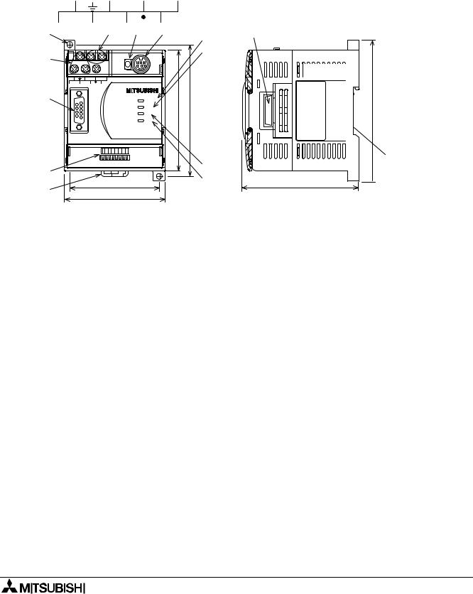
1.2External Dimensions and Each Part Name
Dimensions: mm (inches) |
Weight: Approx. 0.4 kg (0.88 lbs) |
Accessory: GSD files (FD: 1 piece)
Figure 1.1:External Dimensions
|
C O M |
) ) |
|
+ |
||||
|
|
2 4 |
||||||
L |
N |
|
|
|
" " |
|
|
|
c ) |
d ) e ) f46) |
g ) |
||||||
|
|
|
|
5 |
8 |
|||
|
|
|
|
|
||||
|
|
|
|
|
h ) |
|||
b ) |
R U N |
. . |
||||||
|
|
|
|
|
|
|||
|
S T O P |
3 3 |
|
|
||||
|
C O 2M 4 + |
|
|
|
( ( |
|
|
|
L |
N |
|
|
|
|
|
||
|
|
|
|
|
|
|
||
a ) |
|
|
|
P O W E R |
|
|
|
|
|
|
|
|
R U N |
0 |
8 |
|
|
|
|
|
|
B F |
|
|
||
|
|
|
|
D I A |
|
|
|
|
|
|
|
|
F 2X-N 3 2 D 9P -9I F |
|
|
||
|
64 32 16 8 4 |
2 |
1 |
O N |
|
|
|
|
|
|
|
|
|
|
i |
) |
|
|
|
|
|
O F F |
|
|
||
l ) |
|
|
|
|
|
|
j |
) |
|
6 7 |
|
|
|
|
|
||
k ) |
|
|
( 2 . 6 4 " ) |
|
||||
7 5 |
|
|
( 2 . 9 5 " ) |
|
||||
|
|
|
|
|||||
m )


 1 0 5 ( 4 . 1 3 " )
n )
8 7 ( 3 . 4 3 " )
3 " )
a)Connector for Profibus cable (D-SUB 9 pin)
b)Power supply terminals (screws terminal: M3.5 (0.14"))
c)Direct mounting hole (2-φ4.5 (0.18"))
d)24 V DC power terminal (screws terminal: M3.5 (0.14"))
e)RUN/STOP switch: When this switch is in the RUN position, the 32DP-IF will exchange
data with extension units/blocks and special function blocks. If this switch is in the STOP position, the 32DP-IF will exchange only input data with extension units/blocks.
f)Communication port for FX-20P-E and personal computer
g)POWER LED : ON when AC power is supplied.
h) RUN LED |
: ON when 32DP-IF is exchanging data with extension units/blocks and |
|
|
|
special function blocks. |
i) |
BF LED |
: ON when a communication error is detected (No data exchange). |
j) |
DIA LED |
: ON when notice of diagnostic data is detected. |
k)Hook for mounting DIN rail
l)DIP switches for slave address of this unit
m)Connector for extension cable
n)Groove for mounting DIN rail (DIN rail width: 35 mm (1.38"))
1-2

FX2N-32DP-IF Profibus-DP Interface Unit |
Introduction 1 |
1.2.1Pin Configuration
The connector is a 9-pin D-SUB type and the pin configuration is shown below.
Figure 1.2:Pin Layout 9-pin D-SUB
6 7 8 9 1 2 3 4 5
|
Table 1.1: |
Pin Configuration |
|
|||
|
|
Connector |
|
Signal |
Meaning |
|
|
|
|
|
|
|
|
|
|
3 |
|
RXD/TXD-P |
Receive/transmit-Data-P(+) |
|
|
|
|
|
|
|
|
|
|
4 |
|
RTS |
Request to send |
|
|
|
|
|
|
|
|
Assigned |
|
5 |
|
DGND |
Data Ground |
|
|
|
|
|
|
|
|
Not assigned |
|
6 |
|
VP |
Voltage-Plus(+) |
|
|
|
|
|
|
|
|
|
|
8 |
|
RXD/TXD-N |
Receive/transmit-Data-N(+) |
|
|
|
|
|
|
|
|
|
|
1,2,7,9 |
|
NC |
Pin not assigned |
|
|
|
|
|
|
|
|
|
|
|
|
|
|
|
1-3
FX2N-32DP-IF Profibus-DP Interface Unit |
Introduction 1 |
1.3System Configuration
Figure 1.3:System Configuration
|
|
|
DP-master |
|
Profibus-DP network |
|||
|
|
|
|
|
|
|
|
|
|
|
|
|
|
|
|
|
|
|
|
|
|
|
|
|
|
|
Slave or DP-master *1
Slave or DP-master *1
FX2N-32DP-IF Profibus-DP |
Extension I/O units/blocks and |
interface unit *2 |
special function blocks *3 |
*1 The units at each end of the Profibus-DP network must have a terminating resistor. This will either be in the master or slave unit or in the Profibus connector.
*2 For connecting monitoring tool, refer to section 1.3.1
*3 For connecting extension I/O units/blocks and special function blocks, refer to section 1.3.2.
Caution
The parameter data of the 32DP-IF must be set correctly in the DP-master, If the parameter data are not correct, the operation of the module might be affected. For a detailed overview of the parameter of 32DP-IF, refer to chapter 6.
1-4

FX2N-32DP-IF Profibus-DP Interface Unit |
Introduction 1 |
1.3.1Connected Programming Tools
An FX-20P-E or personal computer can be used to monitor the devices of the 32DP-IF or to set parameter data for special function blocks connected to the 32DP-IF. For operating instructions of the FX-20P-E or personal computer, refer to their respective operation manuals. For device numbers and explanation, refer to chapter 4.
Connecting cable is same as FX0N/FX2N programmable controller.
Table 1.2: Connected Programming Tools
|
|
|
|
|
Monitoring Tools |
Description |
|
|
|
|
|
|
FX-20P-E |
“Device Monitor”, “Data Change” and “Forced ON/OFF” in the Online |
|
|
Monitor /Test mode can be used for supported devices. |
|
|
|
|
|
|
|
|
|
|
|
Personal Computer |
“Device Edit” and “Entry Data Monitor” can be used for supported |
|
|
(MELSEC MEDOC PLUS) |
devices. |
|
|
|
|
|
|
|
|
|
1-5

FX2N-32DP-IF Profibus-DP Interface Unit |
Introduction 1 |
1.3.2Connected Extension Units/Blocks
The table below shows extension units/blocks and their data lengths when connected to a 32DP-IF. Data is exchanged between the 32DP-IF and DP-master during every cycle. The maximum amount of data that can be exchanged with the 32DP-IF is 200 bytes of input data and 200 bytes of output data. Please check the specification of the DP-master, it may limit the total amount of exchanged data.
Table 1.3: Connected Extension Units/Blocks and Exchanged Data Length
|
|
|
|
|
|
|
|
|
|
|
|
Items |
Description |
Exchange Data Length |
|
||
|
|
|
|
|
|
|||
|
|
|
Output Data (Y) |
Input Data (X) |
|
|||
|
|
|
|
|
|
|
||
|
|
|
|
|
|
|
|
|
|
|
|
|
FX2N-32ER-ES/UL |
Input = 16 points |
2 Bytes (Y0 ~ Y17) |
2 Bytes (X0 ~ X17) |
|
|
|
|
|
|
|
|||
|
Extension I/O Units |
|
FX2N-32ET-ESS/UL |
Output = 16 points |
|
|||
|
|
|
|
|
|
|||
|
|
|
|
|
|
|
||
|
|
FX2N-48ER-ES/UL |
Input = 24 points |
3 Bytes (Y0 ~ Y27) |
3 Bytes (X0 ~ X27) |
|
||
|
|
|
|
|
||||
|
|
|
|
|
|
|||
|
|
|
|
FX2N-48ET-ESS/UL |
Output = 24 points |
|
||
|
|
|
|
|
|
|
|
|
|
|
|
|
|
|
|
|
|
|
|
|
|
FX2N-16EX-ES/UL |
Input = 16 points |
- |
2 Bytes (X0 ~ X17) |
|
|
|
|
|
Output = 0 point |
|
|||
|
|
|
|
|
|
|
|
|
|
|
FX2N |
|
|
|
|
|
|
|
|
|
FX2N-16EYR-ES/UL |
|
|
|
|
|
|
|
Series |
|
|
|
|
|
|
|
|
|
|
Input = 0 point |
|
|
|
|
|
|
|
FX2N-16EYT-ESS/UL |
2 Bytes (Y0 ~ Y17) |
- |
|
||
|
|
|
|
|
||||
|
|
|
|
Output = 16 points |
|
|||
|
|
|
|
FX2N-16EYS-ES/UL |
|
|
|
|
|
|
|
|
|
|
|
|
|
|
|
|
|
FX0N-8EX-UA1/UL |
Input = 8 points |
|
1 Bytes (X0 ~ X7) |
|
|
|
|
|
|
|
|
||
|
|
|
|
FX0N-8EX-ES/UL |
Output = 0 point |
- |
|
|
|
|
|
|
|
|
|||
|
Extension |
|
|
|
|
|
||
|
|
|
|
|
|
|
||
|
|
|
|
Input = 16 points |
|
|
|
|
|
I/O Blocks |
|
|
FX0N-16EX-ES/UL |
|
2 Bytes (X0 ~ X17) |
|
|
|
|
|
Output = 0 point |
|
|
|||
|
|
|
|
|
|
|||
|
|
|
|
|
|
|
|
|
|
|
|
|
|
|
|
|
|
|
|
FX0N |
|
FX0N-8ER-ES/UL |
Input = 4 points |
1 Bytes (Y0 ~ Y3) |
1 Bytes (X0 ~ X3) |
|
|
|
|
Output = 4 points |
|
||||
|
|
Series |
|
|
||||
|
|
|
|
|
|
|
||
|
|
|
|
|
|
|
|
|
|
|
|
|
FX0N-8EYR-ES/UL |
Input = 0 point |
1 Bytes (Y0 ~ Y7) |
|
|
|
|
|
|
|
|
|
||
|
|
|
|
FX0N-8EYT-ESS/UL |
Output = 8 points |
|
|
|
|
|
|
|
|
|
|
||
|
|
|
|
|
|
|
|
|
|
|
|
|
|
|
|
|
|
|
|
|
|
FX0N-16EYR-ES/UL |
Input = 0 point |
2 Bytes (Y0 ~ Y17) |
|
|
|
|
|
|
|
- |
|
||
|
|
|
|
FX0N-16EYT-ESS/UL |
Output = 16 points |
|
||
|
|
|
|
|
|
|||
|
|
|
|
|
|
|
||
|
|
|
|
|
|
|
|
|
|
|
|
|
|
Digital to analog |
8 Bytes, |
|
|
|
|
|
|
FX2N-4DA |
Analog output data |
|
|
|
|
|
|
|
converter |
|
|
||
|
|
|
|
|
(BFM #1 ~ #4) |
|
|
|
|
|
|
|
|
|
|
|
|
|
|
|
|
|
|
|
|
|
|
Special Function |
|
FX2N-4AD |
Analog to digital |
|
8 Bytes *1 |
|
|
|
|
converter |
|
|
||||
|
Blocks |
|
|
|
|
|
||
|
|
|
|
|
|
|
||
|
|
FX2N-4AD-PT |
PT100 probe |
- |
8 Bytes *2 |
|
||
|
|
|
|
|
||||
|
|
|
|
interface |
|
|||
|
|
|
|
|
|
|
|
|
|
|
|
|
|
|
|
|
|
|
|
|
|
FX2N-4AD-TC |
Thermo-couple |
|
8 Bytes *3 |
|
|
|
|
|
interface |
|
|
||
|
|
|
|
|
|
|
|
|
|
|
|
|
|
|
|
|
|
|
|
|
|
|
|
|
|
|
*1 Total 8 bytes, selection between averaged data (BFM #5 ~ #8) or present data (BFM #9 ~ #12) can be done by GSD file configuration for each channel separately.
1-6

FX2N-32DP-IF Profibus-DP Interface Unit |
Introduction 1 |
*2 Total 8 bytes, selection between °C and °F, averaged or present data can be done by GSD file configuration for each channel separately.
Table 1.4: BFM No. of FX2N-4AD-PT
|
|
|
|
|
Items |
BFM No. |
|
|
|
|
|
|
°C (averaged) |
BFM #5 ~ #8 |
|
|
|
|
|
|
°C (present) |
BFM #9 ~ #12 |
|
|
|
|
|
|
°F (averaged) |
BFM #13 ~ #16 |
|
|
|
|
|
|
°F (present) |
BFM #17 ~ #20 |
|
|
|
|
|
|
|
|
|
*3 Total 8 bytes, selection between °C and °F, averaged or present data and the type of thermocouple can be done by GSD file configuration for each channel separately.
Table 1.5: BFM No. of FX2N-4AD-TC
|
|
|
|
|
Items |
BFM No. |
|
|
|
|
|
|
°C (averaged) |
BFM #5 ~ #8 |
|
|
|
|
|
|
°C (present) |
BFM #9 ~ #12 |
|
|
|
|
|
|
°F (averaged) |
BFM #13 ~ #16 |
|
|
|
|
|
|
°F (present) |
BFM #17 ~ #20 |
|
|
|
|
|
|
|
|
|
1-7

FX2N-32DP-IF Profibus-DP Interface Unit |
Introduction 1 |
1.3.3Configuration Rules
1)Special function blocks: Max. 8 blocks per 32DP-IF.
Check the loading on the 5 V DC bus supply. Consumption values for special function blocks can be found in Table 1.7. For maximum available current see the Table 1.6.
2)Maximum I/O points: 256 or less.
3)Check the loading on the 24 V DC service supply. Look up the number of expansion I/O in Figure 1.4. Find the residual current. This can then be used to power sensors etc.
4)Check total exchanged data length in DP-master, this number might be limited by the DPmaster unit. Data length is exchanged between the 32DP-IF and a DP-master in every cycle.
For the data length of connected extension units/blocks, refer to Table 1.3.
However, the maximum amount of data that can be exchanged with the 32DP-IF is 200 byte inputs and 200 byte outputs.
Table 1.6: 24 and 5 V DC Supply Capacity
|
|
|
|
|
Items |
Power Supply |
|
|
|
|
|
|
24 V DC Service Supply |
500 mA at 24 V DC |
|
|
|
|
|
|
Max. 5 V DC Bus Supply |
220 mA at 5 V DC |
|
|
|
|
|
|
|
|
|
Table 1.7: Power Supply for Special Function Blocks
|
|
|
|
|
|
|
|
|
|
Number of |
Power Supply |
|
|
|
Model |
Description |
|
|
|
|
|
Internal 5 V DC |
External 24 V DC |
|
|||
|
I/O Points |
|
||||
|
|
|
|
|||
|
|
|
(mA) |
(mA) |
|
|
|
|
|
|
|
||
|
|
|
|
|
|
|
|
FX2N-4DA |
Digital to analog converter |
8 |
30 |
200 |
|
|
|
|
|
|
|
|
|
FX2N-4AD |
Analog to digital converter |
8 |
30 |
55 |
|
|
|
|
|
|
|
|
|
FX2N-4AD-PT |
PT100 probe interface |
8 |
30 |
50 |
|
|
|
|
|
|
|
|
|
FX2N-4AD-TC |
Thermo-couple interface |
8 |
30 |
50 |
|
|
|
|
|
|
|
|
|
|
|
|
|
|
|
Figure 1.4:Number of Expansion I/O and 24 V DC Service Supply Capacity (mA)
Number of additional output (points)
> 32 |
|
|
|
|
|
|
|
|
|
|
|
|
|
|
|
|
|
|
Invalid configuration |
||||
32 |
200 |
150 |
100 |
50 |
0 |
|
|||||
|
|
|
|
|
|
|
|
|
|
|
|
24 |
275 |
225 |
175 |
125 |
75 |
25 |
|
|
|
|
|
|
|
|
|
|
|
|
|
|
|
|
|
16 |
350 |
300 |
250 |
200 |
150 |
100 |
50 |
0 |
|
|
|
|
|
|
|
|
|
|
|
|
|
|
|
8 |
425 |
375 |
325 |
275 |
225 |
175 |
125 |
75 |
25 |
|
|
|
|
|
|
|
|
|
|
|
|
|
|
0 |
500 |
450 |
400 |
350 |
300 |
250 |
200 |
150 |
100 |
|
|
|
|
|
|
|
|
|
|
|
|
|
|
|
0 |
8 |
16 |
24 |
32 |
40 |
48 |
56 |
64 |
> 64 |
|
|
|
|
|
|
|
|
|
|
|
|
|
Number of additional input (points)
For extension unit, refer to FX2N Series Hardware Manual.
1-8

FX2N-32DP-IF Profibus-DP Interface Unit |
Introduction 1 |
1.3.4Example Configuration
Figure 1.5:Example Configuration
A Series
PLC
|
|
|
|
|
|
|
|
|
|
Profibus-DP |
|
|
|
|
|
|
|
||
network |
|
|
A1SJ71PB92 (software version E) |
|
|||||
|
|
|
|
|
|
|
|
|
|
|
|
FX2N- |
FX2N-16EX |
FX2N-16EYT |
FX2N- |
FX2N- |
FX2N- |
||
|
|
32DP-IF |
-ES/UL |
-ESS/UL |
4AD |
4DA |
4DA |
||
|
|
|
|
|
|
|
|
|
|
For configuration rules, refer to section 1.3.3.
1)Check special function blocks.
a)Count special function blocks.
This 32DP-IF has 3 special function blocks connected (FX2N-4AD × 1, FX2N-4DA × 2). This configuration is OK as the total number of blocks is less than 8.
b)Check the loading on the 5 V DC bus supply. Consumption values for special function blocks can be found in Table 1.7. For maximum available current see the Table 1.6.
Table 1.8: Check 5 V DC Bus Supply
|
|
|
|
|
|
Items |
Internal 5 V DC |
External 24 V DC |
|
|
|
|
|
|
|
FX2N-4AD |
30 mA |
55 mA |
|
|
|
|
|
|
|
FX2N-4DA |
30 mA |
200 mA |
|
|
|
|
|
|
|
FX2N-4DA |
30 mA |
200 mA |
|
|
|
|
|
|
|
|
|
|
|
|
Total Consumption Values |
90 mA <220 mA |
455 mA |
|
|
|
|
|
|
|
|
|
|
|
This configuration is OK as the 5 V DC bus supply consumption value is less than 220 mA (5 V DC bus supply capacity).
However, this system needs a supply of 455 mA from an external 24 V DC power supply, for the special function blocks. In this case, the 32DP-IF can supply 250 mA for external 24 V DC. See next page (check the loading on the 24 V DC service supply)
1-9

FX2N-32DP-IF Profibus-DP Interface Unit |
Introduction 1 |
2)Check total I/O points and the loading on the 24 V DC service supply. For the loading on the 24 V DC service supply, refer to Figurer 1.4.
Table 1.9: Check Total I/O Points and the Loading on the 24 V DC Service Supply
|
|
|
|
|
|
|
|
|
|
|
|
Addressable I/O |
24 V DC Service Supply |
|
|||
|
|
|
|
|
|
|
|
|
|
Units/Block Name |
|
|
|
Special |
|
|
|
|
Inputs |
|
Outputs |
Function |
Sum I/O |
Sum |
|
|
|
|
|
|
|||||
|
|
(X) |
|
(Y) |
Blocks |
|
||
|
|
|
|
|
|
|||
|
|
|
|
|
(X/Y) |
|
|
|
|
|
|
|
|
|
|
|
|
|
FX2N-32DP-IF |
0 |
|
0 |
- |
|
|
|
|
|
|
|
|
|
Inputs (X) = 16 |
+ 250 mA |
|
|
FX2N-16EX-ES/UL |
16 |
|
0 |
- |
|
||
|
|
Outputs (Y) = 16 |
According to Figure 1.4 |
|
||||
|
|
|
|
|
|
|
||
|
FX2N-16EYT-ESS/UL |
0 |
|
16 |
- |
|
|
|
|
|
|
|
|
|
|
|
|
|
FX2N-4AD |
- |
|
- |
8 |
- |
0 mA |
|
|
|
|
|
|
|
|
|
|
|
FX2N-4DA |
- |
|
- |
8 |
- |
0 mA |
|
|
|
|
|
|
|
|
|
|
|
FX2N-4DA |
- |
|
- |
8 |
- |
0 mA |
|
|
|
|
|
|
|
|
|
|
|
|
|
|
|
|
|
|
|
|
|
16 |
|
16 |
24 |
This configuration can supply 250 mA at |
|
|
|
|
|
|
|
|
|
||
|
|
Total I/O is 56 points <256 points |
24 V DC service supply for other usages. |
|
||||
|
|
|
|
|
|
|
|
|
|
|
|
|
|
|
|
|
|
This configuration is OK as the total I/O points are less than 256. It is also OK with the loading on the 24 V DC service supply, this configuration can supply 250 mA at 24 V DC service supply for other usages.
3)Check the total allowable exchanged data length for each input data and output data in the DP-master, because this number might be limited by the DP-master unit.
Maximum exchanged data length of 32DP-IF can be found in Table 3.3. For the data length of connected extension units/blocks, refer to Table 1.3.
Table 1.10:Check Total Exchanged Data Length
|
|
|
|
|
|
Units/Blocks Name |
Exchanged Data Length |
|
|
|
|
|
|
|
|
Input Data |
Output Data |
|
|
|
|
|
||
|
|
|
|
|
|
FX2N-16EX-ES/UL |
2 bytes |
0 byte |
|
|
|
|
|
|
|
FX2N-16EYT-ESS/UL |
0 byte |
2 bytes |
|
|
|
|
|
|
|
FX2N-4AD |
8 bytes |
0 byte |
|
|
|
|
|
|
|
FX2N-4DA |
0 byte |
8 bytes |
|
|
|
|
|
|
|
FX2N-4DA |
0 byte |
8 bytes |
|
|
|
|
|
|
|
|
|
|
|
|
Total exchanged data length |
10 bytes < 200 bytes *1 |
18 bytes < 200 bytes *1 |
|
|
<244 bytes *2 |
<244 bytes *2 |
|
|
|
|
|
||
|
|
|
|
|
|
|
|
|
|
*1 This value is maximum exchanged data length of 32DF-IF.
*2 This example configuration use A series programmable controllers A1SJ71PB92D (software version is E). This DP-master is limited to 244 bytes of input data and 244 bytes of output data.
This configuration is OK as the each total input data and total output data length is less than 200 bytes.
1-10
FX2N-32DP-IF Profibus-DP Interface Unit |
Wiring and Mounting Arrangements 2 |
2.Wiring and Mounting Arrangements
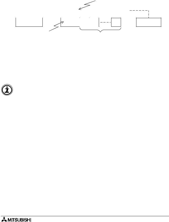
2.1Mounting Arrangements
To prevent a rise in temperature, mount the units to back walls. Never mount them to the floor, ceiling or side wall of an enclosure.
Figure 2.1:Mounting Location
> 50 mm
FX2N-32DP-IF
(1.97")
> 50 mm (1.97")
FX2N-4DA |
FX2N-4AD |
FX2N-16EX -ES/UL |
|
|
|
|
|
|
|
|
> 50 mm (1.97")
FX2N-16EYT
-ESS/UL
> 50 mm (1.97")
Figure 2.2:Mounting Arrangement
2-1
 Loading...