


 Loading...
SOFTWARE MANUAL
FX-PCS-DU/WIN-E

FX Series Programmable Controllers
FX-PCS-DU/WIN-E
Software Manual
Manual number |
: |
JY992D68301 |
Manual revision |
: |
G |
Date |
: |
February 2003 |
Foreword
•This manual contains text, diagrams and explanations which will guide the reader in the correect installation and operation of the FX-PCS-DU/WIN-E.
•Before attempting to install or use the FX-PCS-DU/WIN-E this manual should be read and understood.
•If in doubt at any stage of the installation of the FX-PCS-DU/WIN-E always consult a professional electrical engineer who is qualified and trained to the local and national standards which apply to the installation site.
•If in doubt about the operation or use of the FX-PCS-DU/WIN-E please consult the nearest Mitsubisi Electric distributor.
•This manual is subject to change without notice.
i

FX Series Programmable Controllers
MS,MS-DOS and Windows are registered trademarks of Microsoft Corporation.
IBM and AT are registered trademarks of International Business Machines Corporation.
All other brand and product names are trademarks or registered trademarks of theirrespective owners.
ii

FX Series Programmable Controllers
FAX BACK
Mitsubishi has a world wide reputation for its efforts in continually developing and pushing back the frontiers of industrial automation. What is sometimes overlooked by the user is the care and attention to detail that is taken with the documentation. However, to continue this process of improvement, the comments of the Mitsubishi users are always welcomed. This page has been designed for you, the reader, to fill in your comments and fax them back to us. We look forward to hearing from you.
Fax numbers: |
|
|
Your name: ......................................................... |
Mitsubishi Electric.... |
|
|
........................................................................... |
America |
(01) |
847-478-2253 |
Your company:.................................................... |
Australia |
(02) |
638-7072 |
........................................................................... |
Germany |
(0 21 02) 4 86-1 12 |
Your location:...................................................... |
|
Spain |
(34) |
93-589-1579 |
........................................................................... |
United Kingdom |
(01707) 278-695 |
|
|
Please tick the box of your choice |
|
|
|
What condition did the manual arrive in? |
!Good |
!Minor damage |
!Unusable |
Will you be using a folder to store the manual? |
!Yes |
!No |
|
What do you think to the manual presentation? |
!Tidy |
!Unfriendly |
|
Are the explanations understandable? |
!Yes |
!Not too bad |
!Unusable |
Which explanation was most difficult to understand: ................................................................................
..................................................................................................................................................................
Are there any diagrams which are not clear? |
!Yes |
!No |
|
If so,which: ................................................................................................................................................ |
|
|
|
What do you think to the manual layout? |
!Good |
!Not too bad |
!Unhelpful |
If there one thing you would like to see improved, what is it? ...................................................................
..................................................................................................................................................................
..................................................................................................................................................................
Could you find the information you required easily using the index and/or the contents, if possible please
identify your experience: ...........................................................................................................................
..................................................................................................................................................................
..................................................................................................................................................................
..................................................................................................................................................................
..................................................................................................................................................................
Do you have any comments in general about the Mitsubishi manuals? ...................................................
..................................................................................................................................................................
..................................................................................................................................................................
..................................................................................................................................................................
..................................................................................................................................................................
Thank you for taking the time to fill out this questionnaire. We hope you found both the product and this manual easy to use.
iii

FX Series Programmable Controllers
Guidelines for the safety of the user and protection of the FX-PCS-DU/WIN-E
This manual provides information for the use of the FX-PCS-DU/WIN-E. The manual has been written to be used by trained and competent personnel. The definition of such a person or persons is as follows;
a ) |
Any engineer who is responsible for the planning, design and construction of automatic equipment |
|
using the product associated with this manual should be of a competent nature,trained and qualified |
|
to the local and national standards required to fulfill that role. These engineers should be fully aware |
|
of all aspects of safety with regards to automated equipment. |
b ) |
Any commissioning or service engineer must be of a competent nature,trained and qualified to the |
|
local and national standards required to fulfill that job. These engineers should also be trained in the |
|
use and maintenance of the completed product. This includes being completely familiar with all |
|
associated documentation for the said product. All maintenance should be carried out in accordance |
|
with established safety practices. |
c ) |
All operators of the completed equipment should be trained to use that product in a safe and |
|
coordinated manner in compliance to established safety practices. The operators should also be |
|
familiar with documentation which is connected with the actual operation of the completed equipment. |
Note: the term 'completed equipment' refers to a third party constructed device which contains or uses the product associated with this manual.
Notes on the symbology used in this manual
At various times through out this manual certain symbols will be used to highlight points of information which are intended to ensure the users personal safety and protect the integrity of equipment. Whenever any of the following symbols are encountered its associated note must be read and understood. Each of the symbols used will now be listed with a brief description of its meaning.
iv
FX Series Programmable Controllers
Hardware warnings
Indicates that the identified danger WILL cause physical and property damage.
Indicates that the identified danger could POSSIBLY cause physical and property damage.
Indicates a point of further interest or further explanation.
Software warning
Indicates special care must be taken when using this element of software.
Indicates a special point which the user of the associate software element should be aware of.
Indicates a point of interest or further explanation.
v

FX Series Programmable Controllers
vi

FX Series Programmable Controllers Contents
1. Introduction .......................................................................................... |
1-1 |
1.1 Outline ............................................................................................................... |
1-1 |
1.1.1 List of models compatible with the software DU/WIN ............................................. |
1-1 |
1.1.2 Product configuration (accessory list) .................................................................... |
1-1 |
1.1.3 Major features of the software ................................................................................ |
1-2 |
1.2 How to read this manual .................................................................................... |
1-3 |
1.2.1 Contents described in manual ................................................................................ |
1-3 |
1.2.2 Abbreviations in the text ......................................................................................... |
1-5 |
2. Installation ............................................................................................ |
2-1 |
|
2.1 |
Software installation procedure ......................................................................... |
2-1 |
2.2 |
Operating environments of the personal computer ............................................ |
2-1 |
2.3 |
System configuration ......................................................................................... |
2-2 |
2.4 |
Installation (setup) ............................................................................................. |
2-4 |
2.4.1 Starting up the setup program ................................................................................ |
2-4 |
|
2.5 |
Deleting the application ..................................................................................... |
2-5 |
2.6 |
Installation information ....................................................................................... |
2-6 |
2.6.1 Installation destination directory ............................................................................. |
2-6 |
|
2.6.2 Upper compatibility of the drawing file .................................................................... |
2-7 |
|
3. Starting up and Terminating the Program ............................................ |
3-1 |
|
3.1 |
Starting up the program ..................................................................................... |
3-1 |
3.1.1 Program type .......................................................................................................... |
3-1 |
|
3.1.2 Starting up the program .......................................................................................... |
3-2 |
|
3.2 |
Screen configuration of the DU/WIN .................................................................. |
3-3 |
3.2.1 Basic screen ........................................................................................................... |
3-3 |
|
3.3 |
Terminating the program ................................................................................... |
3-4 |
4. What You Should Know Before Starting Drawing ................................ |
4-1 |
|
4.1 |
Name of each object on the screen ................................................................... |
4-1 |
4.2 |
Types of the DU screen and the F940GOT screen ........................................... |
4-3 |
4.3 |
Objects constituting the screen .......................................................................... |
4-5 |
4.4 |
Functions of tools ............................................................................................... |
4-6 |
4.4.1 Tool type ................................................................................................................. |
4-7 |
|
4.4.2 Modifying the display layout of the tool bar ............................................................ |
4-8 |
|
4.5 |
Common change contents in version upgrade of DU/WIN-E ............................ |
4-9 |
4.6 |
Before starting screen creation for F920GOT-K .............................................. |
4-10 |
4.6.1 How to read this manual ....................................................................................... |
4-10 |
|
4.6.2 Functions and objects provided in the F940GOT but not provided in the |
|
|
F920GOT-K ................................................................................................................... |
4-10 |
|
4.6.3 Difference in specifications between the F920GOT-K and the F940GOT ........... |
4-11 |
|
4.6.4 Colors displayed in the F920GOT-K and the screen creation software ............... |
4-11 |
|
4.6.5 Changing the backlight color ................................................................................ |
4-11 |
|
4.7 |
Before starting screen creation for F930GOT(-K) ............................................ |
4-12 |
4.7.1 How to read this manual ....................................................................................... |
4-12 |
|
4.7.2 Functions provided in the F940GOT but not provided in the F930GOT(-K) ......... |
4-12 |
|
4.7.3 Difference in specifications between the F930GOT(-K) and the F940GOT ......... |
4-12 |
|
4.7.4 Colors displayed in the F930GOT(-K) and the screen creation software ............. |
4-12 |
|
4.8 |
Cautions on screen creation in the GOT-F900 Series ..................................... |
4-13 |
4.8.1 Arrangement of "Touch Key", "Number" and "Ascii" objects ................................ |
4-13 |
|
4.8.2 Key code and function of touch key ..................................................................... |
4-15 |
|
4.8.3 High-quality characters and 6¥8-dot font ............................................................. |
4-16 |
|
vii

FX Series Programmable Controllers Contents
5. Preparation for Drawing and Basic Options ......................................... |
5-1 |
|
5.1 |
Screen creation procedure ................................................................................ |
5-1 |
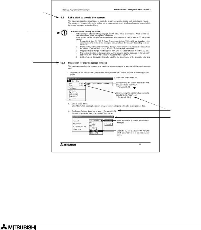
5.2 |
Let's start to create the screen. .......................................................................... |
5-2 |
5.2.1 Preparation for drawing (Screen window) .............................................................. |
5-2 |
|
5.2.2 Creating the screen data newly [New] .................................................................... |
5-5 |
|
5.2.3 Reading and editing the existing screen data (Open) ............................................ |
5-7 |
|
5.2.4 Readable files ......................................................................................................... |
5-8 |
|
5.2.5 Selecting the screen No. and performing additional deletion (Screen List) ............ |
5-9 |
|
5.2.6 Adding and changing the screen No. (Screen Header) ........................................ |
5-10 |
|
5.2.7 Adding, deleting and sorting objects (Object List) ................................................ |
5-12 |
|
5.2.8 Setting the security for system screens ................................................................ |
5-14 |
|
5.3 |
Let’s display characters ................................................................................... |
5-15 |
5.4 |
Let’s turn on output using touch key switch ..................................................... |
5-18 |
5.5 |
Let’s display numeric value (T, C, D) ............................................................... |
5-22 |
5.6 |
Let’s change over screen ................................................................................. |
5-26 |
5.6.1 Screen No. 0 for screen changeover .................................................................... |
5-27 |
|
5.6.2 Screen No. 1 for screen changeover .................................................................... |
5-31 |
|
5.6.3 Screen No. 2 for screen changeover .................................................................... |
5-35 |
|
5.6.4 Setting of control device ....................................................................................... |
5-36 |
|
5.6.5 Setting of "Change Screen (by PLC)" object ........................................................ |
5-38 |
|
5.6.6 Creation of sequence program (reference) .......................................................... |
5-41 |
|
6. Menu Bar Functions ............................................................................. |
6-1 |
6.1 Types and functions of the menu bar ................................................................ |
6-1 |
6.2 Jobs offered by the “File” command .................................................................. |
6-3 |
6.2.1 Saving the screen data to the disk ......................................................................... |
6-4 |
6.2.2 File formats which can be read and saved ............................................................. |
6-5 |
6.2.3 Creating the printout title ........................................................................................ |
6-6 |
6.2.4 Checking the preview before printout ..................................................................... |
6-7 |
6.2.5 Setting and starting printout ................................................................................... |
6-8 |
6.2.6 Samples of printout .............................................................................................. |
6-10 |
6.3 Jobs offered by the “Edit” command ................................................................ |
6-11 |
6.3.1 Deleting, transferring and copying objects (Screen window) ............................... |
6-11 |
6.3.2 Searching the use destination screen No. based on the object name ................. |
6-20 |
6.4 Jobs offered by the “View” command .............................................................. |
6-21 |
6.4.1 Displaying the screen list on the front .................................................................. |
6-22 |
6.4.2 Creating and editing the text library ...................................................................... |
6-23 |
6.4.3 Creating and editing the image library .................................................................. |
6-25 |
6.4.4 Creating and editing the device comment ............................................................ |
6-29 |
6.4.5 Creating and setting the alarm message .............................................................. |
6-31 |
6.4.6 Creating and setting the data for the data file ...................................................... |
6-34 |
6.4.7 Setting the time channel ....................................................................................... |
6-37 |
6.4.8 Setting the sampling condition ............................................................................. |
6-38 |
6.4.9 Creating logos, symbols, etc. using the external character creation function ...... |
6-39 |
6.4.10 Outputting the screen image to the printer (hard copy) ..................................... |
6-41 |
6.4.11 Arranging the DU operation environment by the system setting ........................ |
6-42 |
6.5 Jobs offered by the “Transfer” command ......................................................... |
6-51 |
6.5.1 Preparation for data transfer between the DU ...................................................... |
6-53 |
6.5.2 Executing transfer of the drawing data ................................................................. |
6-57 |
6.5.3 OS transfer function in the F940GOT ................................................................... |
6-61 |
6.5.4 Changing over the port for communication setup ................................................. |
6-63 |
viii
FX Series Programmable Controllers Contents
6.6 Objects offered by the “Other” command ........................................................ |
6-65 |
6.6.1 Error check for the screen data ............................................................................ |
6-66 |
6.6.2 Displaying the memory use capacity .................................................................... |
6-67 |
6.6.3 Displaying the sampling result .............................................................................. |
6-68 |
6.6.4 Displaying the alarm history ................................................................................. |
6-70 |
6.6.5 Displaying the alarm frequency ............................................................................ |
6-72 |
6.7 Functions offered by the Window menu .......................................................... |
6-74 |
6.7.1 Displaying the grid ................................................................................................ |
6-74 |
6.7.2 Setting the grid display ......................................................................................... |
6-75 |
6.7.3 Enlarging and diminishing the screen window ..................................................... |
6-75 |
6.8 Help menu ....................................................................................................... |
6-76 |
6.8.1 Topics index function ............................................................................................ |
6-76 |
6.8.2 Checking the version of the DU/WIN software ..................................................... |
6-77 |
7. Common Drawing Operations .............................................................. |
7-1 |
|
7.1 |
Rule on object selection ..................................................................................... |
7-1 |
7.1.1 Editing the objects to be displayed on the screen .................................................. |
7-1 |
|
7.1.2 Selecting the objects to be displayed on the screen and the objects not to be |
|
|
displayed on the screen .................................................................................................. |
7-2 |
|
7.1.3 Editing the key objects ........................................................................................... |
7-4 |
|
7.1.4 Editing the attribute objects (Scroll and Flashing) in the FX-10DU-E ..................... |
7-6 |
|
7.2 |
Specifying object elements using data files (indirect specification) ................... |
7-7 |
7.3 |
Assigning character strings and graphics in libraries to the DU ........................ |
7-9 |
7.4 |
DU screen specifications ................................................................................. |
7-10 |
8. Object Function Description ................................................................. |
8-1 |
8.1 Setting the "Text" object .................................................................................... |
8-1 |
8.1.1 Text ....................................................................................................................... |
8-2 |
8.1.2 Library Text ............................................................................................................ |
8-4 |
8.2 Setting the "Image" object ................................................................................. |
8-6 |
8.2.1 Image ..................................................................................................................... |
8-8 |
8.2.2 Library Image ....................................................................................................... |
8-10 |
8.3 Setting the "Graph" object ............................................................................... |
8-12 |
8.3.1 Bar Graph ............................................................................................................. |
8-14 |
8.3.2 Trend Graph (Sampling) ....................................................................................... |
8-18 |
8.3.3 Circle Graph ......................................................................................................... |
8-22 |
8.3.4 Panel Meter .......................................................................................................... |
8-24 |
8.3.5 Proportional Bar Graph ....................................................................................... |
8-26 |
8.3.6 Proportional Pie Graph ........................................................................................ |
8-30 |
8.3.7 Line Graph ............................................................................................................ |
8-34 |
8.4 Setting indicators (Indicator) ............................................................................ |
8-37 |
8.4.1 Text indicator ....................................................................................................... |
8-38 |
8.4.2 Image indicator ..................................................................................................... |
8-41 |
8.4.3 Indicator ............................................................................................................... |
8-42 |
8.4.4 Label indicator ...................................................................................................... |
8-43 |
8.4.5 Change screen .................................................................................................... |
8-46 |
8.4.6 Output Indicator .................................................................................................... |
8-47 |
8.4.7 Setting "Overlay Screen" ...................................................................................... |
8-48 |
8.4.8 Buzzer .................................................................................................................. |
8-49 |
8.5 Setting the date/time display (Date/Time) ........................................................ |
8-50 |
8.5.1 Date ...................................................................................................................... |
8-51 |
8.5.2 Time .................................................................................................................... |
8-52 |
8.6 Setting the character code (Ascii) .................................................................... |
8-53 |
ix

FX Series Programmable Controllers Contents
8.7 Setting the numeric (Number) .......................................................................... |
8-57 |
|
8.8 Setting the box (Box) ....................................................................................... |
8-63 |
|
8.9 Setting the circle (Circle) .................................................................................. |
8-66 |
|
8.10 |
Setting the line (Line) ..................................................................................... |
8-69 |
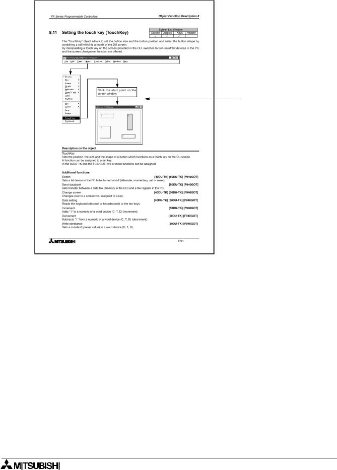
8.11 |
Setting the touch key (TouchKey) .................................................................. |
8-71 |
8.12 |
Setting the keyboard (Keyboard) ................................................................... |
8-77 |
8.13 |
Setting the key function ................................................................................. |
8-80 |
8.13.1 Key function object ............................................................................................. |
8-82 |
|
8.13.2 Switch ................................................................................................................. |
8-83 |
|
8.13.3 Send data bank .................................................................................................. |
8-86 |
|
8.13.4 Change screen ................................................................................................... |
8-87 |
|
8.13.5 Data setting ........................................................................................................ |
8-88 |
|
8.13.6 Increment and Decrement .................................................................................. |
8-90 |
|
8.13.7 Write constant .................................................................................................... |
8-92 |
|
8.14 |
Setting the objects related to the FX-10DU-E ............................................... |
8-93 |
8.15 |
Setting dedicated to handy GOT ................................................................... |
8-95 |
8.15.1 Assignment of LEDs of operation switches ........................................................ |
8-96 |
|
8.15.2 Setting of grip switch .......................................................................................... |
8-97 |
|
8.16 |
Setting of alarm .............................................................................................. |
8-98 |
8.16.1 Alarm List (L) ...................................................................................................... |
8-99 |
|
8.16.2 Alarm History (R) .............................................................................................. |
8-102 |
|
9. Related Information .............................................................................. |
9-1 |
|
9.1 |
Index .................................................................................................................. |
9-1 |
9.1.1 Function index and applicable DU type .................................................................. |
9-1 |
|
9.1.2 Object name index and applicable DU type ........................................................... |
9-4 |
|
9.2 |
Additional functions and corresponding version of the DU ................................ |
9-6 |
9.3 |
Cautions on using the screen data for an other type of PLC ........................... |
9-10 |
9.3.1 Cautions on using the screen data for an other type of PC .................................. |
9-10 |
|
9.3.2 Cautions on change of the DU type ..................................................................... |
9-10 |
|
9.3.3 Cautions on DU type setting when the drawing data is transferred (written) |
|
|
to the DU ....................................................................................................................... |
9-10 |
|
9.4 |
Device list for each PC .................................................................................... |
9-11 |
9.5 |
Control devices ................................................................................................ |
9-25 |
9.5.2 Screen specification registers |
|
|
(The table below indicates the case where D0 is assigned.) ........................................ |
9-28 |
|
9.6 |
Number of objects registered and data size .................................................... |
9-29 |
9.7 |
Data transfer between a general-purpose ROM writer |
|
(preparation before transfer such as connection) .................................................. |
9-36 |
|
9.8 |
Image library data list ....................................................................................... |
9-41 |
9.8.1 Frame .................................................................................................................. |
9-41 |
|
9.8.2 Indicator ............................................................................................................... |
9-44 |
|
9.8.3 Switch ................................................................................................................... |
9-46 |
|
9.8.4 Other(mark) ......................................................................................................... |
9-47 |
|
9.8.5 List of images added in Ver. 2.50 and later .......................................................... |
9-48 |
|
9.9 |
Troubleshooting ............................................................................................... |
9-50 |
9.10 Key code list .................................................................................................. |
9-52 |
|
x
FX Series Programmable Controllers
1Introduction
2Installation
3Starting up and Terminating the Program
4What You Should Know Before Starting Drawing
5Preparation for Drawing and Basic Operations
6Menu Bar Functions
7Common Drawing Operations
8Object Function Description
9Related Information

FX Series Programmable Controllers

FX Series Programmable Controllers |
Introduction 1 |
1.Introduction
This section describes the major functions of the software FX-PCS-DU/WIN-E and the outline of this manual. The applicable data access units are also described here. Make sure to read this section before using the software.
1.1Outline
The software package FX-PCS-DU/WIN-E (hereafter referred to as "software DU/WIN-E") is a screen creation software for graphic operation terminals (GOT-F900) and data access units (DU) running on the Microsoft Windows 95/98/Me/NT4.0 (hereafter referred to as "Windows").
1.1.1List of models compatible with the software DU/WIN
Table:1.1
|
|
|
|
|
|
|
|
|
|
|
|
|
|
FX-PCS-DU/WIN-E |
V1.0 |
V2.0 |
V2.1 |
V2.2 |
V2.3 |
V2.4 |
V2.5 |
V2.6 |
V2.7 |
V2.8 |
|
|
version |
|
||||||||||
|
|
|
|
|
|
|
|
|
|
|
|
|
|
|
|
|
|
|
|
|
|
|
|
|
|
|
FX-10DU-E |
" |
" |
" |
" |
" |
" |
" |
" |
" |
" *3 |
|
|
FX-25DU-E |
" |
" |
" |
" |
" |
" |
" |
" |
" |
" |
|
|
|
|
|
|
|
|
|
|
|
|
|
|
|
FX-30DU-E |
" |
" |
" |
" |
" |
" |
" |
" |
" |
" |
|
|
|
|
|
|
|
|
|
|
|
|
|
|
|
FX-40DU-ES |
" |
" |
" |
" |
" |
" |
" |
" |
" |
" |
|
|
|
|
|
|
|
|
|
|
|
|
|
|
|
FX-40DU-TK-E |
" |
" |
" |
" |
" |
" |
" |
" |
" |
" |
|
|
|
|
|
|
|
|
|
|
|
|
|
|
|
FX-50DU-TK-E |
" |
" |
" |
" |
" |
" |
" |
" |
" |
" |
|
|
FX-50DU-TKS-E |
|
||||||||||
|
|
|
|
|
|
|
|
|
|
|
|
|
|
F940GOT-SBD-E |
|
" |
" |
" |
" |
" |
" |
" |
" |
" |
|
|
F940GOT-LBD-E |
|
|
|||||||||
|
|
|
|
|
|
|
|
|
|
|
|
|
|
F940GOT-SWD-H-E |
|
|
" |
" |
" |
" |
" |
" |
" |
" |
|
|
F940GOT-LWD-H-E |
|
|
|
||||||||
|
|
|
|
|
|
|
|
|
|
|
|
|
|
F930GOT-BWD-E |
|
|
|
" |
" |
" |
" |
" *1 |
" *1 |
" *1 |
|
|
F940WGOT-TWD-E*2 |
|
|
|
|
|
|
" |
" |
" |
" |
|
|
F920GOT-BBD5-K-E |
|
|
|
|
|
|
|
|
" |
" |
|
|
F930GOT-BBD-K-E |
|
|
|
|
|
|
|
|
|
||
|
|
|
|
|
|
|
|
|
|
|
|
|
|
|
|
|
|
|
|
|
|
|
|
|
|
*1 Screen creation in the longitudinal installation is supported in the F930GOT. *2 Screen creation with screen division into 2 or 3 portions is not supported.
*3 FX1S and FX1N Series PLCs are applicable to the screen data transfer function of FX-10DU.
1.1.2Product configuration (accessory list)
Check the software DU/WIN while referring to this checklist to confirm that the following accessories are supplied.
Product model:FX-PCS-DU/WIN-E
•System disk SW0PC-FXDU/WIN-E Floppy disk 3.5-inch (1.44 MB) 3 disks
•Manual (this manual) JY992D68301
The cable to connect the DU and the personal computer is offered as an option.Check the system configuration, and use a cable suitable to your personal computer.
1-1
FX Series Programmable Controllers |
Introduction 1 |
1.1.3Major features of the software
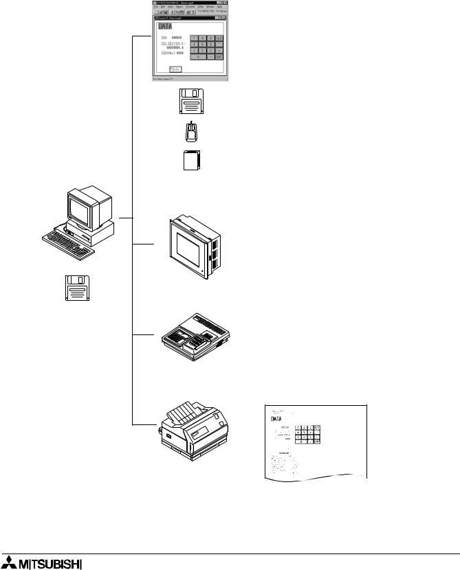
The software DU/WIN has the diversified convenient functions as follows. The operability is excellent because the features of the Windows are offered and the graphic interface is provided. Two or more applications and two or more screen data files can be started up at the same time. You can edit the data while looking at two or more DU screens at the same time.
Screen edition
Data access unit
P
O
W
E
General-purpose ROM writer
SW0PC-FXDU/WIN-E
Printer
•Two or more screen files and screen displays can be opened at the same time.
•The DU screen display size can be enlarged. The position of each component can be adjusted easily.
•Data can be saved in the storage media connected to the personal computer such as a floppy disk or hard disk.
•The drawing software data of the DOS version is available due to the upper compatibility.
•The basic operations are performed using the mouse.
•This software is similar to a general Windows application, so can be easily learned.
•The company logo, symbols, etc. can be created using the external character creation function.
•The libraries for character examples and graphics can be created.
•The screen data can be transferred to the DU.
•The screen data saved in the DU can be read and edited.
•The FX-25DU-E to the FX-50DU-TKS-E are applicable.
•The FX-10DU-E is also applicable (However, the drawing software of the DOS version is not applicable yet.)
•The screen data can be written to and read from the EP-ROM memory.
Use appropriate communication software when transferring the data between a ROM writer.The DU/WIN software can save the data in the Intel Hex format offered for transfer between a ROM writer.
•The graphic (screen data) can be created.
Sampling data
Alarm history
Screen name list, etc.
1-2
FX Series Programmable Controllers |
Introduction 1 |
1.2How to read this manual
This paragraph describes the description format, the abbreviations in the text, the key symbols, etc. adopted in this manual.
1.2.1Contents described in manual
This manual adopts the following format. Refer to this page for index.
In "9. Related Information", you can utilize the function list and the object list for index. Refer to Section 9 also.
General format of manual
 Section title
Paragraph title
Detailed explanation of each paragraph
Note
Notes and cautions described in main text above
Subtitle
 Reference page
Screen
1-3
FX Series Programmable Controllers |
Introduction 1 |
Format of "8. Object Function Description"
 Window which can be set
Paragraph 7.1
Operation flow from the tool bar (The Screen window indicates an example after an object is created. The object dialog box is actually displayed.)
 Applicable models
1-4

FX Series Programmable Controllers |
Introduction 1 |
1.2.2Abbreviations in the text
The following terms may be abbreviated in the text in this manual.
•Microsoft Windows®95, 98, NT4.0 and 2000 may be referred to as “Windows”
•The software kit for creating the display screen “FX-PCS-DU/WIN-E (for Windows)” may be referred to as “software DU/WIN”.
•The general-purpose personal computer PC/AT compatible machine may be referred to as “personal computer”.
A floppy disk may be referred to as “FD”. A floppy disk drive may be referred to as “FD drive”. Each of them may be referred to as “disk”.
•The data access unit may be referred to as “DU”. Each DU model may be referred to as follows.
- Data access unit FX-10DU-E - - - - - - - - - - - - - - - - - - - - - - - - - - - - - - - - - 10DU - Data access unit FX-25DU-E - - - - - - - - - - - - - - - - - - - - - - - - - - - - - - - - - 25DU - Data access unit FX-30DU-E - - - - - - - - - - - - - - - - - - - - - - - - - - - - - - - - - 30DU - Data access unit FX-40DU-ES - - - - - - - - - - - - - - - - - - - - - - - - - - - - - - - - 40DU
- Data access unit FX-40DU-TK-E - - - - - - - - - - - - - - - - - - - - - - - - - - - - - - 40DU-TK - Data access unit FX-50DU-TK-E, FX-50DU-TKS-E - - - - - - - - - - - - - - - - - 50DU-TK
•The graphic operation terminal is referred to as "GOT-F900".
- Graphic operation terminal Model F94#GOT-SWD-E/F94#GOT-LWD-E - - F940GOT
- Graphic operation terminal Model F940WGOT-TWD-E - - - - - - - - - - - - - - - F940WGOT - Graphic operation terminal Model F930GOT-BWD-E - - - - - - - - - - - - - - - - F930GOT
- Graphic operation terminal Model F930GOT-BBD-K-E - - - - - - - - - - - - - - - F930GOT-K
(The abbreviation notation of the F930GOT in the text is included. Refer to the following graphic operation terminal if it has the same functions as the F940GOT in the text.)
- Graphic operation terminal Model F920GOT-BBD5-K-E - - - - - - - - - - - - - - F920GOT-K
• The devices of the programmable controller (PC) are abbreviated as follows. Input: X
Output: Y Auxiliary relay: M State: S
Timer: T Counter: C Data register: D
The output contacts of X, Y, M, X, T and C are called “bit devices”. T, C and D are called “word devices”.All of them are called “devices”.
*In this manual, the devices of the FX PC are described. In any PC other than the FX PC, read the devices described in this manual as the devices in the corresponding PC.
•The liquid crystal screen of the display unit and the notebook personal computer may be referred to as “CRT”.
•The handy graphic operation terminal is referred to as "handy GOT".
-Handy GOT
Read it as "F940GOT" because its functions are equivalent to those of F94!GOT-SWD/LWD-E.
- Handy GOT F94!GOT-SBD/LBD-H-E - - - - - - - - - - - - - - - - - - - - - - - - - - Handy GOT
•The GOT and the handy GOT may be referred to as "DU".
1-5

FX Series Programmable Controllers |
Introduction 1 |
MEMO
1-6
FX Series Programmable Controllers
1Introduction
2Installation
3Starting up and Terminating the Program
4What You Should Know Before Starting Drawing
5Preparation for Drawing and Basic Operations
6Menu Bar Functions
7Common Drawing Operations
8Object Function Description
9Related Information

FX Series Programmable Controllers

FX Series Programmable Controllers |
Installation 2 |
2.Installation
This section describes how to install the software FX-PCS-DU/WIN-E.
Make sure to read the connection of each equipment, the operating environments of the personal computer, the compatibility between files, etc. described in this section before installing the software.
2.1Software installation procedure
This paragraph describes the procedure to install the software DU/WIN to the personal computer and start it up.
•Checking the operating environments and setting up the software
2.2Operating environments of the personal computer
Check whether the hardware and the OS (operating system) of the personal computer are compatible with this software.
2.3System configuration
2.4Installation (setup)
The method to select the cable connecting the personal computer and the DU is described.
The procedure to execute the file “SETUP.EXE “saved in the system disk.
2.2Operating environments of the personal computer
This paragraph describes the system specifications required to use the software DU/WIN.
Table:2.1
|
|
|
|
|
|
|
|
|
|
|
|
|
Item |
PC/AT compatible machine |
|
|
|
|
|
|
|
|
|
|
|
|
|
|
|
|
|
|
Microsoft Windows 95 English version |
|
|
|
|
|
|
|
|
Microsoft Windows 98*1 English version |
|
|
|
|
|
OS |
Microsoft Windows Millennium Edition English version (Windows Me*2) |
|
|
||
|
|
|
Microsoft Windows NT4.0*1 (Workstation) English version (Service Pack 3 or later) |
|
|
|||
|
|
|
|
|
|
Microsoft Windows 2000*3 English version |
|
|
|
|
|
|
|
|
Microsoft Windows XP |
|
|
|
|
|
|
|
|
Operation of each OS shall be assured in the personal computer to be used. |
|
|
|
|
|
|
|
|
|
|
|
|
|
|
|
|
|
Microsoft Windows 95: CPU i486SX or better one |
|
|
|
|
|
|
|
|
Microsoft Windows 98: CPU i486DX (66 MHz) or better one |
|
|
|
|
|
Computer main body |
Microsoft Windows Me: CPU Pentium 150 MHz or better one |
|
|
||
|
|
|
|
|
|
Microsoft Windows NT4.0: CPU i486(25 MHz) or better one |
|
|
|
|
|
|
|
|
Microsoft Windows 2000: CPU i486(133 MHz) or better one |
|
|
|
|
|
|
|
|
|
|
|
|
|
|
|
|
|
Microsoft Windows 95: 8 MB or more (12 MB or more is recommended.) |
|
|
|
|
|
|
|
|
Microsoft Windows 98: 16 MB or more (32 MB or more is recommended.) |
|
|
|
|
|
Required memory |
Microsoft Windows Me: 32 MB or more |
|
|
||
|
|
|
|
|
|
Microsoft Windows NT4.0: 16 MB or more |
|
|
|
|
|
|
|
|
Windows 2000: 32 MB or more (64 MB or more is recommended.) |
|
|
|
|
|
|
|
|
|
||
|
|
|
Hard disk capacity |
Free space of 3 MB or more |
|
|
||
|
|
|
|
|
|
|
|
|
|
|
|
Floppy disk unit |
3.5-inch (2HD) floppy disk drive × 1 unit |
|
|
||
|
|
|
A disk formatted as 1.44 MB shall be able to be read. |
|
|
|||
|
|
|
|
|
|
|
|
|
|
|
|
Display |
Video display adaptor whose resolution is VGA or better |
|
|
||
|
|
|
|
|
|
|
|
|
|
|
|
Interface |
RS-232C serial interface (COM1 to COM4 shall be able to be changed over.) |
|
|
||
|
|
|
|
|
|
|||
|
|
|
Printer interface |
|
|
|||
|
|
|
|
|
|
|
|
|
|
|
|
|
|
|
|
|
|
|
|
|
|
|
|
Printer in accordance with the OS above |
|
|
|
|
|
Printer |
The drawing data in the FX-50DU-TKS-E and the F940GOT-SWD-E is compatible |
|
|
||
|
|
|
|
|
|
with a color printer |
|
|
|
|
|
|
|
|
|
||
|
|
|
Others |
Mouse or other pointing device |
|
|
||
|
|
|
|
|
|
|
|
|
*1 |
It is supported in the DU/WIN Ver. 2.20 or later. |
|||||||
*2 |
It is supported in the DU/WIN Ver. 2.60 or later. |
|||||||
*3 |
It is supported in the DU/WIN Ver. 2.50 or later. |
|||||||
|
|
|
|
|
|
|
|
|
|
|
|
|
|
|
2-1 |
|
|
|
|
|
|
|
|
|||
|
|
|
|
|
|
|
|
|
FX Series Programmable Controllers |
Installation 2 |
2.3System configuration
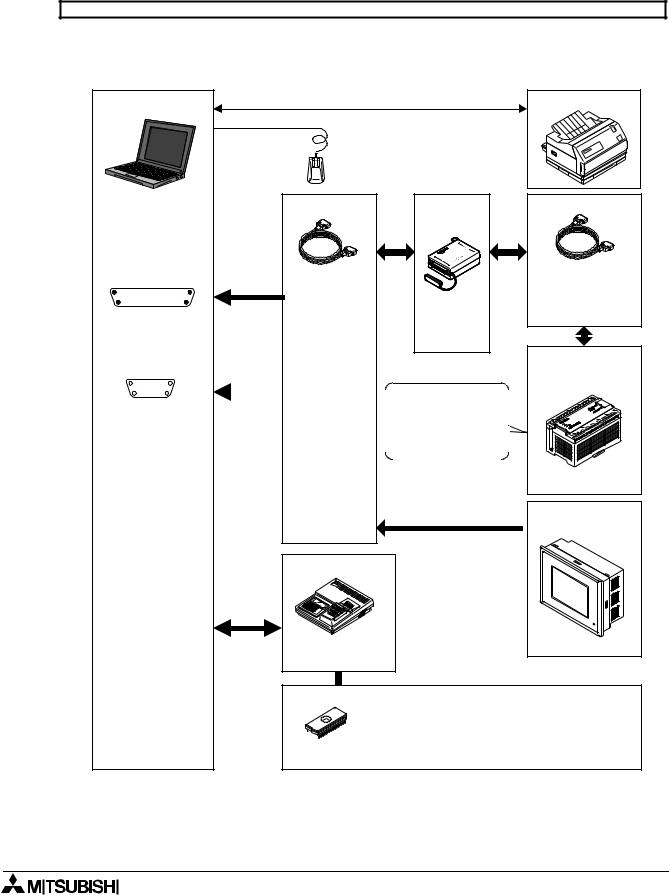
The cable connecting the personal computer and the DU is offered as an option. Select a suitable one as described below.
10DU, 25DU, 30DU, 40DU, 40DU-TK and 50DU-TK
Select the cable suitable to the shape of the RS-232C interface connector on the personal computer among 1) to 2).
The FX-10DU-E shall be connected to the FX Series PC.
Personal computer |
|
|
Printer |
|
Mouse |
|
|
Shape of RS-232C |
Cable (option) |
I/F |
Cable (option) |
connector in |
|
(option) |
|
personal computer |
|
|
|
Dsub 25-pin (female) |
|
|
FX1S, FX0N, FX1N, |
|
! |
|
|
|
FX2N, FX2NC |
|
|
1)Cable |
|
FX-422CAB0 |
# |
" |
F2-232CAB |
FX-232AW |
FX, FX2C |
|
|
FX-422CAB |
||
|
|
(3m, 9.84ft) |
||
|
|
or |
||
|
|
|
||
|
|
|
|
|
|
|
|
FX-232AWC |
Programmable |
Dsub 9-pin (male) |
|
|
||
|
|
controller (in 10DU |
||
|
|
|
|
|
exclusively)
|
|
|
2)Cable |
|
The screen data in |
|
|
|
|
|
the 10DU is required |
|
|
|
|||||
|
|
|
F2-232CAB-1 |
|
|
|
|||
|
|
|
(3m, 9.84ft) |
|
to be transferred and |
|
|
|
|
|
|
|
|
|
written once to the |
|
|
|
|
|
|
|
|
|
|
|
|
||
|
|
|
|
|
memory in the PC. |
|
|
|
|
|
|
|
|
|
|
|
|
||
|
|
|
|
|
|
|
|
|
|
|
|
|
|
|
|
|
|
|
|
FX Series PC
DU (in any model  other than 10DU)
ROM writer
PECKER 11 (manufactured by AVAL)
EPROM memory (refer to note below.)
$FX-EPROM-512 or equivalent to 27C512 (512 kB)
$FX-EPROM-1M or M27C1001-**F
(1 MB) manufactured by SGS-TOMSON
[30DU] [40DU] [40DU-TK]
[50DU-TK]
2-2
FX Series Programmable Controllers |
Installation 2 |
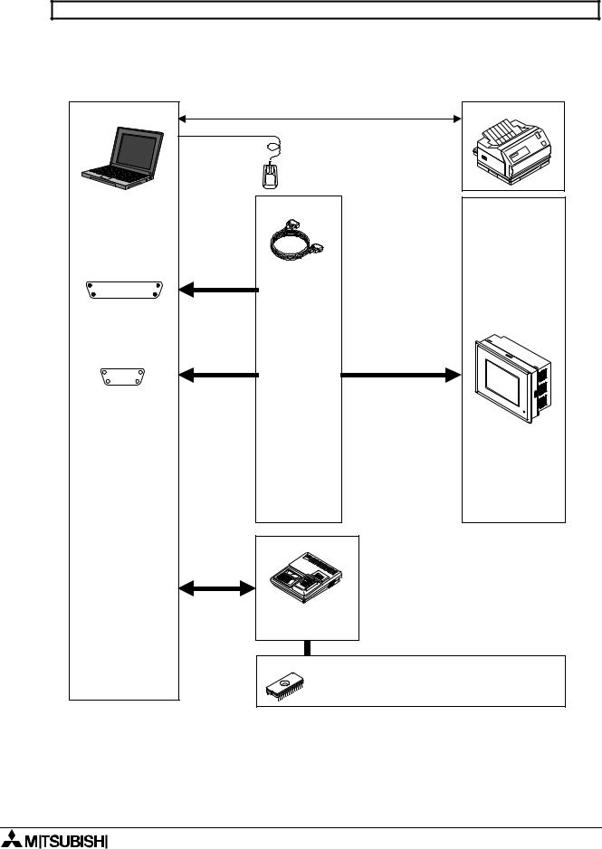
F920GOT-K, F930GOT(-K), F930GOT, F940GOT, F940WGOT and Handy GOT
Select the cable suitable to the shape of the RS-232C interface connector on the personal computer among 1) to 2).
The cables 2) and are different from those for the DU shown in the previous page. Pay attention to the model name.
Personal computer
Shape of RS-232C connector in personal computer
Dsub 25-pin (female)
!
#"
Dsub 9-pin (male)
Mouse
Cable (option)
1)Cable F2-232CAB -1 (3m, 9.84ft)
2)Cable FX-232CAB-1 (3m, 9.84ft)
Dsub 9-pin to RS-232C connector on GOT
Printer |
F940WGOT
F940GOT
F930GOT(-K)
F920GOT-K
Handy GOT
ROM writer
PECKER 11 (manufactured by AVAL)
EPROM memory (refer to note below.)
$ FX-EPROM-4M or M27C4002-**F [F940GOT] (4 MB) manufactured by SGS-TOMSON
2-3
FX Series Programmable Controllers |
Installation 2 |
2.4Installation (setup)
The following three methods are available to install the software DU/WIN to the Windows.
In this manual, the general method a) is adopted.
a ) |
Select “Start” and “Save As”, enter the setup file name, then execute installation. |
b ) |
Display the floppy disk file list from the drive offered by “My Computer”, then execute the |
|
SETUP.EXE. |
c ) |
Select “My Computer”, “Control panel” and “Add/Remove Programs”, then execute installation. |
It is recommended to make the backup of the system disk before starting installation.
2.4.1Starting up the setup program
It is supposed that the Windows is running.
1 ) Insert the system disk 1 into the floppy disk drive.
2 ) Click “Start” of the Windows. Place the cursor on “Save As” on the menu, and click the mouse for execution.
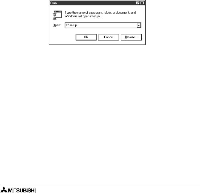
3 ) Enter the drive name, colon (:) and the yen mark (\) in this order. Enter the setup file name “SETUP”. The drive name varies depending on the model of the personal computer, the drive connected, etc. as follows.
The first floppy disk drive is fixed to “Drive A”, and the second floppy disk drive is fixed to “Drive B”. When the floppy disk drive used is “Drive A”, enter “a:\setup”.
4 ) Click the OK button or press the Enter key.
The installer is started up. Perform the operation in accordance with the instruction displayed in the dialog box.
For example, in the case of “User information”, make sure to enter both the name and the company name, then click the Next button.
When installation is finished, the FXDU icon is registered in the start menu program.
When setup is completed, proceed to “3. Starting up and Terminating the Program”.
2-4
FX Series Programmable Controllers |
Installation 2 |
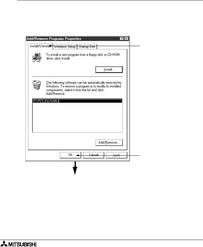
2.5Deleting the application
The software DU/WIN can be easily deleted from the hard disk of the personal computer using the “Add/ Remove Programs” function of the Windows.
This paragraph describes the deletion procedure.
Make sure to make the backup before starting deletion when the files of screen data, external character data, comments, etc. are included in the folder.
Deletion procedure
1 ) |
Double-click the “My Computer” icon. |
2 ) |
Double-click the “Control panel” icon in the “My Computer” folder. |
3 ) |
Double click the “Add/Remove Programs” icon. |
|
The “Add/Remove Programs Property” dialog box is open. |
4 ) |
Select the “Install/Uninstall”. |
|
The list of applications registered in the box is displayed. Select “FX-PCS-DU/WIN-E” in the list. |
|
Click the Details button. |
1.Select the “Install/Uninstall”.
 2. The application list is displayed in the box.
Select “FX-PCS-DU/WIN-E”.
3. Click it for execution.
Deletion is executed.
2-5

FX Series Programmable Controllers |
Installation 2 |
2.6Installation information
2.6.1Installation destination directory
When the software DU/WIN is installed in the initial setting, the system program is written in the following directory.
C:\Program Files\FX-PCS-DU-WIN-E\System file list
\IMAGES\Image library files
Table:2.2 System file list
|
File name |
Contents |
|
|
|
|
|
|
FXDUWIN.EXE |
Execution file |
|
|
|
|
|
|
FXDUWIN.HLP |
Help file |
|
|
|
|
|
|
FXDUWIN.CNT |
|
|
|
|
|
|
|
|
|
|
Table:2.3 Image library file list
File name
FRAMEB**.BMP
LAMPLC**.BMP etc.*1
*1 Refer to "9.7 Image library data list"
2-6
FX Series Programmable Controllers |
Installation 2 |
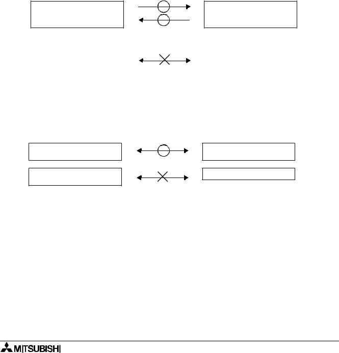
2.6.2Upper compatibility of the drawing file
Compatibility between DOS version and Window version
A drawing file created using the FX-PCS-DU/AT-EE (DOS version) can be read using the DU/WIN software. However, have in mind that the screen data which is newly created or edited using the DU/WIN software and saved in a file (DUP format) cannot be read using the software of the DOS version.
To edit a file using the software of the DOS version, the screen data should be saved in the GDT format. Though files have been created using the software of the DOS version for external characters and printers title (document footers in the DU/WIN software), such files cannot be handled by the DU/WIN software. However, the external character data and the printer title data can be read because they are included in the screen data.
Files created using the software |
Files created using software |
of the DOS version |
DU/WIN |
Created using |
Created using |
FX-PCS-DU/AT-EE |
|
Screen data ××××.GDT (including external character files and printer titles)
Sampling |
××××.SDF |
Alarm history |
××××.HST |
External character file |
|
|
××××.UDL |
Printer title |
××××.PTL |
|
|
Compatibility between DU/WIN V1. × and DU/WIN V2. ×
Screen data ××××.DUP (including external files and document footers)
Sampling |
××××.TXT |
Alarm history |
××××.TXT |
Alarm count |
××××.TXT |
|
|
The F940GOT Series display unit added by version upgrade (to V2.0) of the DU/WIN software cannot be read by a version former than V2.0. DU files which have been handled by V1.0 can be read.
Ver1. ×
10DU, 25DU, 30DU, 40DU-TK, 50DU-TK
Not compatible with F940GOT Series
Ver2. ×
10DU, 25DU, 30DU, 40DU-TK, 50DU-TK
F940GOT Series
Compatibility when the Windows version and the DOS version are used together
When using upgraded objects and added objects of the DU and the F940GOT, make sure to use the compatible software of the DOS version and the Windows version.
If a file is read by the software of incompatible version, errors will occur in the drawing data saved in the file. For compatible versions, refer to "9.2 Additional functions and corresponding version of the DU".
2-7

FX Series Programmable Controllers |
Installation 2 |
MEMO
2-8
Loading...