


FX0S
Table of contents
 Loading...
Mitsubishi Electronics FX0S, FX2NC, FX, FX0, FX0N User Manual
...
PROGRAMMING MANUAL
THE FX SERIES OF PROGR AMM ABLE CONTROLLER
(FX0, F X0S, F X0N, F X , F X
2C, FX2N, FX2NC
)


FX Series Programmable Controllers
g
g
g
y
g
y
j
FX Series Programmable Controllers
Programming Manual
Manual number : JY992D48301
Manual revision : J
Date : November 1999
Foreword
• This manual contains text, dia
the correct pro
• Before attemptin
understood.
• If in doubt at an
electrical en
which appl
• If in doubt about the operation or use of the PLC please consult the nearest
Mitsubishi Electric distributor.
• This manual is sub
ramming and operation of the PLC.
to install or use the PLC this manual should be read and
stage of the installation of the PLC always consult a professional
ineer who is qualified and trained to the local and national standards
to the installation site.
ect to change without notice.
rams and explanations which will guide the reader in
i

FX Series Programmable Controllers
ii

y
y
y
g
g
y
y
y
g
y
y
y
y
y
y
g y
y
y y
y
y
FX Series Programmable Controllers
FAX BACK - Combined Programming Manual (J)
Mitsubishi has a worl d wide rep utation fo r its eff orts i n continual l
the frontiers of industrial automation. What is sometimes overlooked b
and attention to detail that is taken with the documentation. However,to continue this process
of improvement, the comments of the Mitsubishi users are alwa
been desi
ward to hearin
Please tick the box of
Fax numbers: Your name....................................................
Mitsubishi Electric.... .....................................................................
America (01) 847-478-2253 Your compan
Australia (02) 638-7072 .....................................................................
German
South Africa (0111) 444-8304 .................... ................................. ................
United Kin
What condition did the manual arrive in?
Will
ned for you,the reader ,t o fill in your comments and fax them back to us. W e look fo r-
from you.
our choice;
(0 21 02) 4 86-1 12 Your location: ...............................................
dom (01707) 278-695
Good
ou be using a folder to store the manual?
developing and pushing back
the user is the care
s welcomed. This page has
..............................................
Minor damage
Yes
Unusable
No
What do
Are the explanations understandable?
Which explanation was most difficult to understand:..................................................................
....................................................................................................................................................
Are there an
If so,which:..................................................................................................................................
What do
If there one thin
....................................................................................................................................................
....................................................................................................................................................
Could
ble please identif
....................................................................................................................................................
....................................................................................................................................................
....................................................................................................................................................
....................................................................................................................................................
Do
....................................................................................................................................................
....................................................................................................................................................
....................................................................................................................................................
....................................................................................................................................................
ou think to the manual presentation?
Yes
diagrams which are not clear?
ou think to the manual layout?
ou would like to see improved,what is it?......................................................
ou find the information you required easily using the index and/or the contents,if possi-
our experience: ...........................................................................................
ou have any comments in general about the Mitsubishi manuals?.....................................
Good
Tid
Not too bad
Yes
Not too bad
Un-friendl
Unusable
No
Un-helpful
Thank
and this manual easy to use.
ou for taking the time to fill out this questionnaire. W e hope you found both the
product
iii

FX Series Programmable Controllers
iv
FX Series Programmable Controllers
y
y
g
g
y
j
g
y
y
y
g
y
y
y
g
g
g
y
g
Guidelines for the Safety of the User and Protection of the Programmable
Controller (PLC)
This manual provides information for the use of the FX family of PLC’s. The manual has been
written to be used b
persons is as follows;
trained and competent personnel. The definition of such a person or
a) An
engineer who is responsible for the planning, design and construction of automatic
equipment usin
the product associated with this manual should b e of a competent
nature, trained and qua lified to the local an d national standa rds required to fulfill tha t
role. These en
ineers should be fully aware of all aspects of safety with regards to
automated equipment.
b) An
commissioning or service engineer must be of a competent nature, trained and
qualified to the local and national stand ards required to fulfill that
ob. These engineers
should also be trained in the use and maintenance of the completed product. This
includes bein
completely familiar with all associat ed documentation for the said
product. All maintenance should be carried out in acc ordance with established safet
practices.
c) All operators of the completed equipment should be trained to use that product in a safe
and coordinated manner in compliance to established safet
practices. The operators
should also be familiar with documentation which is connected with the actual operation
of the completed equipment.
Note :
the term ‘completed equipment’ refers to a third part
constructed device which
contains or uses the product associated with this manual.
Note’s on the Symbols used in this Manual
At various times throu
information which are intended to ensure the users personal safet
equipment. Whenever an
be read and understood. Each of the s
its meanin
.
h out this manual certain symbols will be used to highlight points of
and protect the integrity of
of the following symbols are encountered its associated note must
mbols used will now be listed with a brief descript ion of
Hardware Warnings
1) Indicates t hat the identified dan
2) Indicates that the identified dan
damage.
3) Indicates a point of further interest or further explanation.
Software Warning s
4) Indicates special care must be taken when usin
5) Indicates a special point which the user of the associate software element should
be aware of.
6) Indicates a point of interest or further explanation.
WILL
er
er could
cause physical and property damage.
POSSIBLY
cause physical and propert
this element of software.
v

FX Series Programmable Controllers
vi

g
g
g
g
g
g
g
g
g
FX Series Programmable Controllers
Contents
1. Introduction............................................................................................1-1
1.1 Overview..............................................................................................................1-1
1.2 What is a Pro
rammable Controller? ..................................................................1-2
1.3 What do You Need to Pro
1.4 CPU version numbers .........................................................................................1-3
1.4.1 FX0N CPU versions...................................................................................................1-3
1.4.2 FX and FX
2C
1.5 Special considerations for programming equipment ....... .. ... ............... .. ... ...........1-4
1.5.1 FX CPU version 3.07 or later and FX2C ................................................................... 1-4
1.5.2 FX
2N
(C) CPU all versions ........................................................................................1-5
2. Basic Program Instructions ...................................................................2-1
2.1 What is a Program?.... .. ... .. .. .. ... .. .. .... ... .. .. .. .. ... .. .. .. .. ..... .. .. .. ... .. .. .. ... .. .. .... ... .. .. .. .. ...2-1
2.2 Outline of Basic Devices Used in Pro
2.3 How to Read Ladder Lo
2.4 Load, Load Inverse ..............................................................................................2-3
2.5 Out.......................................................................................................................2 -4
2.5.1 Timer and Counter Variations ...................................................................................2-4
2.5.2 Double Coil Desi
2.6 And, And Inverse.................................................................................................2-6
2.7 Or, Or Inverse......................................................................................................2-7
2.8 Load Pulse, Load Trailin
2.9 And Pulse, And Trailin
2.10 Or Pulse, Or Trailin
2.11 Or Block.............................................................................................................2-11
2.12 And Block ..........................................................................................................2-12
2.13 MPS, MRD and MPP......................................... .. .. .. ..........................................2-13
2.14 Master Control and Reset................................................... ...............................2-15
2.15 Set and Reset................. ................................. ................................. .................2-17
2.16 Timer, Counter (Out & Reset)................................... .. .. .. .. .. ...............................2-18
2.16.1 Basic Timers, Retentive Timers And Counters........................................................2-18
2.16.2 Normal 32 bit Counters ...........................................................................................2-19
2.16.3 Hi
2.17 Leading and Trailing Pulse................................................................................2-20
2.18 Inverse...............................................................................................................2-21
2.19 No Operatio n . .. .. ............................... ... .. ............................... .. .. .........................2-22
2.20 End ....... .. ............................................... .. .. ............................... .. ... ............... .. .. .2 -23
h Speed Counters ..............................................................................................2-19
ram a PLC? ..............................................................1-2
CPU versions.......................................................................................1-3
ramming..................................................2-1
ic..................................................................................2-2
nation..... ...... ....... ...... ....... ...... ...... ....... ...... ....... ...... ....... ...... ....... ...2-5
Pulse. .. .. ................ .. .. ............... ... .. .............................2-8
Pulse.............................................................................2-9
Pulse................................................................................2-10
i

g
g
g
g
g
g
g
g
g
g
y
y
g
g
y
y
g
g
y
FX Series Programmable Controllers
3. STL Programming.................................................................................3-1
3.1 What is STL, SFC And IEC1131 Part 3?.............................................................3-1
3.2 How STL Operates..............................................................................................3-2
3.2.1 Each step is a program .............................................................................................3-2
3.3 How To Start And End An STL Program.............................................................3-3
3.3.1 Embedded STL programs .........................................................................................3-3
3.3.2 Activatin
3.3.3 Terminatin
3.4 Moving Between STL Steps................................................................................3-5
3.4.1 Using SET to drive an STL coil .................................................................................3-5
3.4.2 Usin
3.5 Rules and Techniques For STL programs...........................................................3-7
3.5.1 Basic Notes On The Behavior Of STL programs.......................................................3-7
3.5.2 Sin
3.6 Restrictions Of Some Instructions When Used With STL..................................3-10
3.7 Usin
3.8 Usin
STL To Select The Most Appropriate Program .......................................3-11
STL To Activate Multiple Flows Simultaneously......................................3-12
3.9 General Rules For Successful STL Branchin
3.10 General Precautions When Usin
3.11 Pro
3.11.1 A Simple STL Flow..................................................................................................3-16
3.11.2 A Selective Branch/ First State Mer
ramming Examples ....................................................................................3-16
3.12 Advanced STL Use............................................................................................3-20
new states.................................................................................................3-3
an STL Program....................................................................................3-4
OUT to drive an STL coil.................... ...... ...... ....... ...... ....... ...... ....... ...... ....... ... 3-6
le Signal Step Control ........................................................................................3-9
..................................................3-14
The FX-PCS/AT-EE Software.....................3-15
e Example Program...................................... .3-18
4. Devices in Detail....................................................................................4-1
4.1 Inputs...................................................................................................................4-1
4.2 Outputs ................................................................................................................4-2
4.3 Auxiliar
4.3.1 General Stable State Auxiliary Relays ......................................................................4-3
4.3.2 Batter
4.3.3 Special Dia
4.3.4 Special Sin
4.4 State Relays ........................................................................................................4-6
4.4.1 General Stable State - State Relays .........................................................................4-6
4.4.2 Batter
4.4.3 STL Step Rela
4.4.4 Annunciator Fla
4.5 Pointers .............................................................................................................4-10
4.6 Interru p t Po in te r s ............. ............... .. ... .............................. ... .. ...........................4-11
4.6.1 Input Interrupts ........................................................................................................4-12
4.6.2 Timer Interrupts.......................................................................................................4-12
4.6.3 Disablin
4.6.4 Counter Interrupts ...................................................................................................4-13
4.7 Constant K.........................................................................................................4-14
4.8 Constant H.........................................................................................................4-14
4.9 Timers................................................................................................................4-15
4.9.1 General timer operation...........................................................................................4-16
4.9.2 Selectable Timers.................................. ............................................. ....... ...... ....... .4-16
4.9.3 Retentive Timers .....................................................................................................4-17
4.9.4 Timers Used in Interrupt and ‘CALL’ Subroutines ...................................................4-18
4.9.5 Timer Accurac
4.10 Counters............................................................................................................4-19
4.10.1 General/ Latched 16bit UP Counters ......................................................................4-20
4.10.2 General/ Latched 32bit Bi-directional Counters.......................................................4-21
Relays....................................... ............................... .............................4-3
Backed/ Latched Auxiliary Relays.................................................................4-4
nostic Auxiliary Relays ...................................... ....... ...... ....... ...... ....... ... 4-5
le Operation Pulse Relays.....................................................................4-5
Backed/ Latched State Relays............... ...... ....... ...... ....... ...... ....... ...... ....... ...4-7
s .......................................................................................................4-8
s .....................................................................................................4-9
Individual Interrupts .................................................................................4-13
.......................................................................................................4-18
ii

y
y
y
)
g
y
g
g
y
g
g
g
y
FX Series Programmable Controllers
4.11 High Speed Counters........................................................................................4-22
4.11.1 Basic High Speed Counter Operation .....................................................................4-23
4.11.2 Availabilit
4.11.3 Availabilit
4.11.4 Availabilit
4.11.5 1 Phase Counters - User Start and Reset (C235 - C240) .......................................4-29
4.11.6 1 Phase Counters - Assi
4.11.7 2 Phase Bi-directional Counters (C246 to C250) ....................................................4-31
4.11.8 A/B Phase Counters (C252 to C255) ......................................................................4-32
of High Speed Counters on FX0, FX0S and FX0N PLC’s......................4-24
of High Speed Counters on FX, FX2C PLC’s........................................4-25
of High Speed Counters on FX
4.12 Data Registers...................................................................................................4-33
4.12.1 General Use Registers............................................................................................4-34
4.12.2 Batter
4.12.3 Special Dia
4.12.4 File Re
4.12.5Externall
Backed/ Latched Registers.................... ...... ....... ...... ....... ...... ....... ..............4-35
nostic Registers...................................................................................4-35
isters ..........................................................................................................4-36
Adjusted Registers...................................................................................4-37
4.13 Index Registers............. ... .. .. .. ... .. .. .. ..... .. .. .. .. ... .. .. .. .. ... .... .. .. ... .. .. .. ... .. .. .. ..... .. .. .. .. .4-38
4.13.1 Modifying a Constant...............................................................................................4-39
4.13.2 Misuse of the Modifiers ...........................................................................................4-39
4.13.3 Usin
Multiple Index Registers................................................................................4-39
4.14 Bits, Words, BCD and Hexadecimal..................................................................4-40
4.14.1 Bit Devices, Individual and Grouped .......................................................................4-40
4.14.2 Word Devices..........................................................................................................4-42
4.14.3 Interpretin
4.14.4 Two’s Compliment...................................................................................................4-45
Word Data............................................................................................4-42
4.15 Floating Point And Scientific Notation ...............................................................4-46
4.15.1 Scientific Notation....................................................................................................4-47
4.15.2 Floatin
4.15.3 Summar
Point Format..............................................................................................4-48
Of The Scientific Notation and Floating Point Numbers..........................4-49
2N(C
PLC’s ..........................................4-28
ned Start and Reset (C241 to C245)..............................4-30
iii

FX Series Programmable Controllers
5. Applied Instructions...............................................................................5-1
5.1 Program Flow-Functions00 to 09 ........................................................................5-4
5.1.1 CJ (FNC 00) ..............................................................................................................5-5
5.1.2 CALL (FNC 01)..........................................................................................................5-7
5.1.3 SRET (FNC 02).........................................................................................................5-8
5.1.4 IRET, EI, DI (FNC 03, 04, 05) ...................................................................................5-9
5.1.5 FEND (FNC 06).......................................................................................................5-11
5.1.6 WDT (FNC 07) ........................................................................................................5-12
5.1.7 FOR, NEXT (FNC 08, 09) .......................................................................................5-13
5.2 Move And Compare - Functions 10 to 19..........................................................5-16
5.2.1 CMP (FNC 10).........................................................................................................5-17
5.2.2 ZCP (FNC 11) .........................................................................................................5-17
5.2.3 MOV (FNC 12) ........................................................................................................5-18
5.2.4 SMOV (FNC 13)......................................................................................................5-18
5.2.5 CML (FNC 14)................................. ...... ....... ...... ...... ....... ...... ..................................5-19
5.2.6 BMOV (FNC 15) .....................................................................................................5-20
5.2.7 FMOV (FNC 16) ......................................................................................................5-21
5.2.8 XCH (FNC 17).............................................................................. ...... ....... ...... ....... . 5 -21
5.2.9 BCD (FNC18)........................... ............................................. ....... ...... ....... ...... ....... .5-22
5.2.10 BIN (FNC 19) .. ....... .......................................................................................... ....... .5-22
5.3 Arithmetic And Logical Operations -Functions 20 to 29 ....................................5-24
5.3.1 ADD (FNC 20).............................................................................. ...... ....... ...... ....... . 5 -25
5.3.2 SUB (FNC 21) ........................................................................................................5-26
5.3.3 MUL (FNC 22)................................. ...... ....... ...... ...... ....... ...... ....... ...... ....... ..............5-27
5.3.4 DIV (FNC 23).. ....... ...... ........................................................................................... .5-2 8
5.3.5 INC (FNC 24) .........................................................................................................5-29
5.3.6 DEC (FNC 24) ...................................... ............................................. ....... ...... ....... .5-29
5.3.7 WAND (FNC 26)......................................................................................................5-30
5.3.8 WOR (FNC 27)........................................................................................................5-30
5.3.9 WXOR (FNC 28) .....................................................................................................5-31
5.3.10NEG (FNC 29) .........................................................................................................5-31
5.4 Rotation And Shift - Functions 30 to 39.............................................................5-34
5.4.1 ROR (FNC 30).........................................................................................................5-35
5.4.2 ROL (FNC 31) .........................................................................................................5-35
5.4.3 RCR (FNC 32)......................................................................................................... 5-36
5.4.4 RCL (FNC 33) .........................................................................................................5-36
5.4.5 SFTR (FNC 34) .......................................................................................................5-37
5.4.6 SFTL (FNC 35)........................................................................................................5-37
5.4.7 WSFR (FNC 36)......................................................................................................5-38
5.4.8 WSFL (FNC 37).......................................................................................................5-38
5.4.9 SFWR (FNC 38)......................................................................................................5-39
5.4.10 SFRD (FNC 39).......................................................................................................5-40
5.5 Data Operation - Functions 40 to 49 ....................................................... ..........5-42
5.5.1 ZRST (FNC 40) .......................................................................................................5-43
5.5.2 DECO (FNC 41) ......................................................................................................5-43
5.5.3 ENCO (FNC 42) ......................................................................................................5-44
5.5.4 SUM (FNC 43).........................................................................................................5-45
5.5.5 BON (FNC 44).........................................................................................................5-45
5.5.6 MEAN (FNC 45) ......................................................................................................5-46
5.5.7 ANS (FNC 46) .........................................................................................................5-47
5.5.8 ANR (FNC 47).............................................................................. ...... ....... ...... ....... . 5 -47
5.5.9 SQR (FNC 48).........................................................................................................5-48
5.5.10 FLT (FNC 49) ..........................................................................................................5-49
iv

FX Series Programmable Controllers
5.6 High Speed Processing - Functions 50 to 59 ....................................................5-52
5.6.1 REF (FNC 50) .........................................................................................................5-53
5.6.2 REFF (FNC 51) .......................................................................................................5-53
5.6.3 MTR (FNC 52)......................................................................................................... 5-54
5.6.4 HSCS (FNC 53).......................................................................................................5-55
5.6.5 HSCR (FNC 54) .......... ....... ............................................. ...... ....... ...... ....... ...... ....... .5-56
5.6.6 HSZ (FNC 55) .........................................................................................................5-57
5.6.7 SPD (FNC 56) .........................................................................................................5-60
5.6.8 PLSY (FNC 57) ..... ...... ....... ...... ....... ...... ....... ...... ...... ....... ........................................5-61
5.6.9 PWM (FNC 58)........................................................................................................5-62
5.6.10 PLSR (FNC 59) .......................................................................................................5-63
5.7 Handy Instructions - Functions 60 to 69............................................................5-66
5.7.1 IST (FNC 60)...........................................................................................................5-67
5.7.2 SER (FNC 61) .........................................................................................................5-69
5.7.3 ABSD (FNC 62).......................................................................................................5-70
5.7.4 INCD (FNC 63)........................................................................................................5-71
5.7.5 TTMR (FNC 64).......................................................................................................5-72
5.7.6 STMR (FNC 65) .......... ....... ...... ....... ...... ....... ...... ............................................. ....... .5-72
5.7.7 ALT (FNC 66)..........................................................................................................5-73
5.7.8 RAMP (FNC 67) ......................................................................................................5-73
5.7.9 ROTC (FNC 68) .......... ....... ...... ....... ............................................. ...... ....... ...... ....... .5-75
5.7.10 SORT (FNC 69).......................................................................................................5-77
5.8 External FX I/O Devices - Functions 70 to 79 ...................................................5-80
5.8.1 TKY (FNC 70)..........................................................................................................5-81
5.8.2 HKY (FNC 71) .........................................................................................................5-82
5.8.3 DSW (FNC 72) ........................................................................................................5-83
5.8.4 SEGD (FNC 73) ......................................................................................................5-84
5.8.5 SEGL (FNC 74).......................................................................................................5-85
5.8.6 ARWS (FNC 75).......... ....... ...... ....... ...... ....... ...... ...... ....... ...... ....... ...........................5-87
5.8.7 ASC (FNC 76) .........................................................................................................5-88
5.8.8 PR (FNC 77)............................................................................................................5-89
5.8.9 FROM (FNC 78)......................................................................................................5-90
5.8.10 TO (FNC 77)............................................................................................................5-91
5.9 External FX Serial Devices - Functions 80 to 89...............................................5-94
5.9.1 RS (FNC 80)............................................................................................................5-96
5.9.2 RUN (FNC 81)......................................................................................................... 5-97
5.9.3 ASCI (FNC 82) ........................................................................................................5-99
5.9.4 HEX (FNC 83) .......................................................................................................5-100
5.9.5 CCD (FNC 84)....................................................................................................... 5-101
5.9.6 VRRD (FNC 85) .......... ....... ...... ....... ...... ....... ...... ............................................. ...... 5-102
5.9.7 VRSD (FNC 86).....................................................................................................5-102
5.9.8 PID (FNC 88).. ....... ...... ....... ...... ....... ...... ....... .........................................................5-103
5.10 External F2 Units - Functions 90 to 99 ............................................................5-111
5.10.1 MNET (FNC 90) .... ...... ............................................. ....... ...... ....... ...... ....... ...... ...... 5-11 2
5.10.2 ANRD (FNC 91) .... ...... ....... ............................................. ...... ....... ...... ....... ...... ...... 5-11 2
5.10.3 ANWR (FNC 92)....................................................................................................5-113
5.10.4 RMST (FNC 93) .... ...... ............................................. ....... ...... ....... ...... ....... ...... ...... 5-11 3
5.10.5 RMMR (FNC 94) ...................................................................................................5-114
5.10.6 RMRD (FNC 95)....................................................................................................5-115
5.10.7 RMMN (FNC 96) ...................................................................................................5-115
5.10.8 BLK (FNC 97)........................................................................................................5-116
5.10.9 MCDE (FNC 98).................................................................................................... 5-117
v

g
g
g
g
g
g
FX Series Programmable Controllers
5.11 Floating Point 1 & 2 - Functions 110 to 129 ....................................................5-119
5.11.1 ECMP (FNC 110) ..................................................................................................5-121
5.11.2 EZCP (FNC 111) ...................................................................................................5-121
5.11.3 EBCD (FNC 118)...................................................................................................5-122
5.11.4 EBIN (FNC 119) ....................................................................................................5-122
5.11.5 EADD (FNC 120)...................................................................................................5-123
5.11.6 EAUB (FNC 121)...................................................................................................5-124
5.11.7 EMUL (FNC 122)...................................................................................................5-124
5.11.8 EDIV (FNC 123) ....................................................................................................5-125
5.11.9 ESQR (FNC 127) ..................................................................................................5-125
5.11.10INT (FNC 129) ......................................................................................................5-126
5.12 Trigonometry - FNC 130 to FNC 139 ..............................................................5-128
5.12.1 SIN (FNC 130) ....... ...... ....... ...... .............................................................................5-129
5.12.2 COS (FNC 131).....................................................................................................5-130
5.12.3 TAN (FNC 132) .....................................................................................................5-130
5.13 Data Operations 2 - FNC 140 to FNC 149 ............................................. .........5-132
5.13.1 SWAP (FNC 147) ..................................................................................................5-133
5.14 Real Time Clock Control - FNC 160 to FNC 169.............................................5-136
5.14.1 TCMP (FNC 160) ............................................... ...... ....... ...... ....... ...... ....... ...... ...... 5-13 7
5.14.2 TZCP (FNC 161) ...................................................................................................5-138
5.14.3 TADD (FNC 162)...................................................................................................5-139
5.14.4 TSUB (FNC 163) ...................................................................................................5-140
5.14.5 TRD (FNC 166) .....................................................................................................5-141
5.14.6 TWR (FNC 167) ....................................................................................................5-142
5.15 Gray Codes - FNC 170 to FNC 179 .................... .. .. ........................................5-144
5.15.1 GRY (FNC 170).....................................................................................................5-145
5.15.2 GBIN (FNC 171)....................................................................................................5-145
5.16 Inline Comparisons - FNC 220 to FNC 249.....................................................5-148
5.16.1 LD compare (FNC 224 to 230) .............................................................................. 5-149
5.16.2 AND compare (FNC 232 to 238)...........................................................................5-150
5.16.3 OR compare (FNC 240 to 246) .............................................................................5-151
6. Diagnostic Devices................................................................................6-1
6.1 PLC Status (M8000 to M8009 and D8000 to D8009)..........................................6-2
6.2 Clock Devices (M8010 to M8019 and D8010 to D8019) ...................................6-3
6.3 Operation Fla
6.4 PLC Operation Mode (M8030 to M8039 and D8030 to D8039) .........................6-5
6.5 Step Ladder (STL) Fla
6.6 Interrupt Control Fla
6.7 Error Detection Devices (M8060 to M8069 and D8060 to D6069) .....................6-8
6.8 Link And Special Operation Devices (M8070 to M8099 and D8070 to D8099) ..6-9
6.9 Miscellaneous Devices (M8100 to M8119 and D8100 to D8119) .....................6-10
6.10 Communication Adapter Devices, i.e. 232ADP, 485ADP ................................6-10
6.11 Hi
h Speed Zone Compare Table Comparison Flags . .. .. ................ .. .. ............6-11
6.12 Miscellaneous Devices (M8160 to M8199) .......................................................6-12
6.13 Index Re
6.14 Up/Down Counter Control (M8200 to M8234 and M8200 to D8234) ..... ..........6-14
6.15 Hi
h Speed Counter Control (M8235 to M8255 and D8235 to D8255) ............6-14
6.16 Error Code Tables.............................. ................................. ..............................6-15
s...................................................................................................6-4
s (M8040 to M8049 and D8040 to D8049) ...................6-6
s (M8050 to M8059 and D8050 to D8059) ......................6-7
isters (D8180 to D8199) ................. ................................. .................6-13
vi

g
g
y
g
g
g
g
g
g
g
g
g
g
g
g
y
g
g
FX Series Programmable Controllers
7. Execution Times And Instructional Hierarchy........................................7-1
7.1 Basic Instructions ................................................................................................7-1
7.2 Applied Instructions ............................................................................................7-3
7.3 Hierarchical Relationships Of Basic Pro
7.4 Batch Processin
7.5 Summar
of Device Memory Allocations...........................................................7-14
7.6 Limits Of Instruction Usa
7.6.1 Instructions Which Can Only Be Used Once In The Main Program Area ...............7-16
7.6.2 Instructions Which Are Not Suitable For Use With 110V AC Input Units ................7-16
8. PLC Device Tables................................................................................8-1
8.1 Performance Specification Of The FX0 And FX0S ............................................. 8-1
8.2 Performance Specification Of The FX
8.3 Performance Specification Of The FX (CPU versions 2.0 to 3.06) .....................8-4
8.4 Performance Specification Of The FX
(CPU versions from 3.07) And FX
8.5 Performance Specification Of The FX
9. Assigning System Devices....................................................................9-1
9.1 Addressing Extension Modules...........................................................................9-1
9.2 Usin
9.2.1 Using the FX2-24EI With A F-16NP/NT ....................................................................9-3
9.2.2 Usin
9.2.3 Usin
9.2.4 Usin
9.3 Parallel Link Adapters..........................................................................................9-6
9.4 Real Time Clock Function ...................................................................................9-7
9.4.1 Setting the real time clock .........................................................................................9-8
The FX2-24EI With F Series Special Function Blocks .............................. 9-2
the FX2-24EI With A F2-6A.............................................................................9-4
the FX2-24EI With A F2-32RM .......................................................................9-4
the FX2-24EI With A F2-30GM .......................................................................9-5
ram Instruction s .................. .. ............7-12
...............................................................................................7-14
e ...............................................................................7-16
0N
............................................................8-2
2C
(all versions) ......................................8-6
2N(C)
.......................................................8-8
10.Points Of Technique...........................................................................10-1
10.1 Adva nced Programming Points.... ............... ... .. ............... .. ... .............................10-1
10.2 Users of DC Powered FX Units.........................................................................10-1
10.3 Usin
10.3.1 A RUN/STOP push button configuration.................................................................10-2
10.3.2 Remote RUN/STOP control ....................................................................................10-3
10.4 Constant Scan Mode.........................................................................................10-4
10.5 Alternatin
10.6 Usin
10.7 Indexin
10.8 Readin
10.9 Measurin
10.9.1 A 1 msec timer pulse measurement........................................................................10-6
10.9.2 A 0.1 msec timer pulse measurement.....................................................................10-7
10.10Using The Execution Complete Flag, M8029 ...................................................10-7
10.11Creatin
10.12An Example S
10.13Usin
10.14Communication Format...................................................................................10-18
10.14.1Specification of the communication parameters:..................................................10-18
10.14.2Header and Terminator Characters...................................................................... 10-19
10.14.3Timin
10.14.48 bit or 16 bit communications..............................................................................10-23
The Forced RUN/STOP Flags.................................................................10-2
ON/OFF States................................................................................10-4
Battery Backed Devices For Maximum Advantage.................................10-5
Through Multiple Display Data Values................................................10-5
And Manipulating Thumbwheel Data ............... .. .................................10-6
a High Speed Pulse Input.................................. .. .. .. .. ......................10-6
a User Defined MTR Instruction........................................ .................10-8
stem Application Using STL And IST Program Control............10-8
The PWM Instruction For Motor Control...............................................10-15
diagrams for communications:..................................................................10-20
vii

g
g
g
FX Series Programmable Controllers
10.15PID Programming Techniques........................................................................10-24
10.15.1Keeping MV within a set range.............................................................................10-24
10.15.2Manual/Automatic chan
10.15.3Usin
10.15.4Other tips for PID pro
the PID alarm signals .............................. ...... ....... ...... ....... ...... ....... ...... ...... 10 -2 5
10.16Additional PID functions..................................................................................10-26
10.16.1Output Value range control (S3+1 b5)..................................................................10-26
10.17Pre-tuning operation ............................................................. ..........................10-27
10.17.1Variable Constants ............................................................................................... 10-27
10.18Example Autotuning Program.........................................................................10-28
11.Index...................................................................................................11-1
11.1 Index..................................................................................................................11-1
11.2 ASCII Character Codes.....................................................................................11-9
11.3 Applied Instruction List ....................................................................................11-10
e over................... ...... ...... ....... ...... ....... ...... ....... ...... ...... 10 -2 4
ramming............................................................................10-25
viii
FX Series Programmable Controllers Introduction 1
1 Introduction
2 Basic Program Instructions
3 STL Programming
4 Devices in Detail
5 Applied Instructions
6 Diagnostic Devices
7 Instruction Execution Times
8 PLC Device Tables
9 Assigning System Devices
10 Points of Technique
11 Index

FX Series Programmable Controllers Introduction 1
g
g
Chapter Contents
1. Introduction............................................................................................1-1
1.1 Overview..............................................................................................................1-1
1.2 What is a Pro
1.3 What do You Need to Pro
1.4 CPU version numbers .........................................................................................1-3
1.4.1 FX0N CPU versions...................................................................................................1-3
1.4.2 FX and FX
1.5 Special considerations for programming equipment ....... .. ... ............... .. ... ...........1-4
1.5.1 FX CPU version 3.07 or later and FX2C ................................................................... 1-4
1.5.2 FX
2N
rammableCo ntro l le r? ......... .. ... .. .. .. .. ... .. .. .... ... .. .. .. ... .. .. .. .. ... .... .. .. ... 1-2
ram a PC? ................................................................1-2
2C
CPU versions.......................................................................................1-3
CPU all versions .............................................................................................1-5
1. Introduction
g
g
g
y
y
y
y
ying
g
g
FX
0(S)
FX
0N
FX FX
(2C)
FX
2N(C)
1.1 Overview
1) Scope of this manual
This manual
0S
, FX
0, FX2N
FX
the PLC hardware and installation, refer to the appropriate manual supplied with the unit.
2) How to use this manual
This manual covers all the functions of the hi
Controller (PLC). For this reason, the followin
to show which PLCs that section applies to;
Introduction 1
ives details on all aspects of operation and programming for FX, FX2C, FX0N,
and FX
2NC
programmable controllers (PLCs). For all information relating to
hest specification Programmable (Logic)
indicator is included in relevant section titles
FX
0(S)
- “FX
- “FX
0(S)
0N
FX FX
” - All FX0 and FX0S PLCs
” - All FX0N PLCs
(2C)
FX
0N
- “FX” - All FX and FX
- “FX
- - All FX
- “FX
(2C)
” - All FX and FX2 PLCs (CPU versions 3.07 or later)
2C
PLCs (see page 1-4)
2N(C)
” - All FX2N and FX
FX
2N(C)
2
PLCs (CPU ver 2.30 or earlier)
2NC
Shaded boxes indicate
the applicable PLC t
PLCs
pe
If an indicator box is half shaded, as shown to the
FX
0(S)FX0N
FX FX
(2C)
FX
2N(C)
left, this means that not all the functions described in
the current section appl
to that PLC. The text
explains in further detail or makes an independent
reference.
If there are no indicator boxes then assume the section applies to all PLC t
pes unless
otherwise stated.
3) FX famil
This is a generic term which is often used to describe all Programmable Controllers without
identif
4) CPU version numbers and pro
As Mitsubishi up
individual types or model names.
ramming support
rades each model different versions have different capabilities.
- Please refer to section 1.4 for details about version numbers and capabil it ies.
- Please refer to section 1.5 for details about peripheral support for each model.
1-1
1.2 What is a Programmable Controller?
g
y
gg
g
y
g
gy
g
y
g
y
g
g
g
g
y
g
FX
0(S)
FX0N FX FX(2C)
FX2N(C)
FX
0(S)
FX0N FX FX(2C)
FX2N(C)
A Programmable Logic Controller (PLC or programmable controller) is a device that a user can
pro
ram to perform a series or sequence of events. These events are triggered by stimuli
(usuall
counted occur-rences. Once an ev ent tri
or OFF electronic control
will continuall
outputs at the programmed specific times.
called inputs) received at the PLC or through delayed actions such as time delays or
ear or the physical actuation of devices. A programmable controller
‘loop’ through its internal ‘user defined’ program waiting for inputs and givin
Introduction 1
ers, it actuates in the outside world by switching ON
Note on termin o lo
The term pro
control s
‘Pro
rammable Logic Controller ’, ‘PLC’ or ‘programmable controller ’ to de scribe the same
control s
stem under one descriptive na me. Sometimes engineers use the term
stem.
The construction of a pro
element where the pro
Processin
Unit or MPU. Other terms commonly heard to describe this device are ‘base unit’,
:
rammable controller is a generic word used to bring all the elements making the
rammable controller can be broken down into component parts. The
ram is loaded, s tored and pr ocessed is often known as th e Main
‘controller’ and ‘CPU’. The term CPU is a little misleadin
ma
contain local CPU devices. A Main CPU (or more correctly a Main Processing Unit)
controls these local CPUs throu
h a communication network or bus.
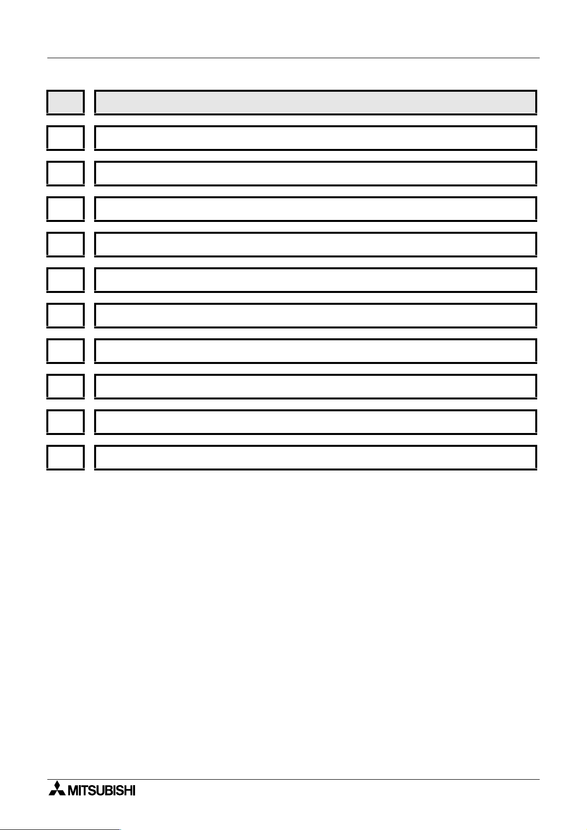
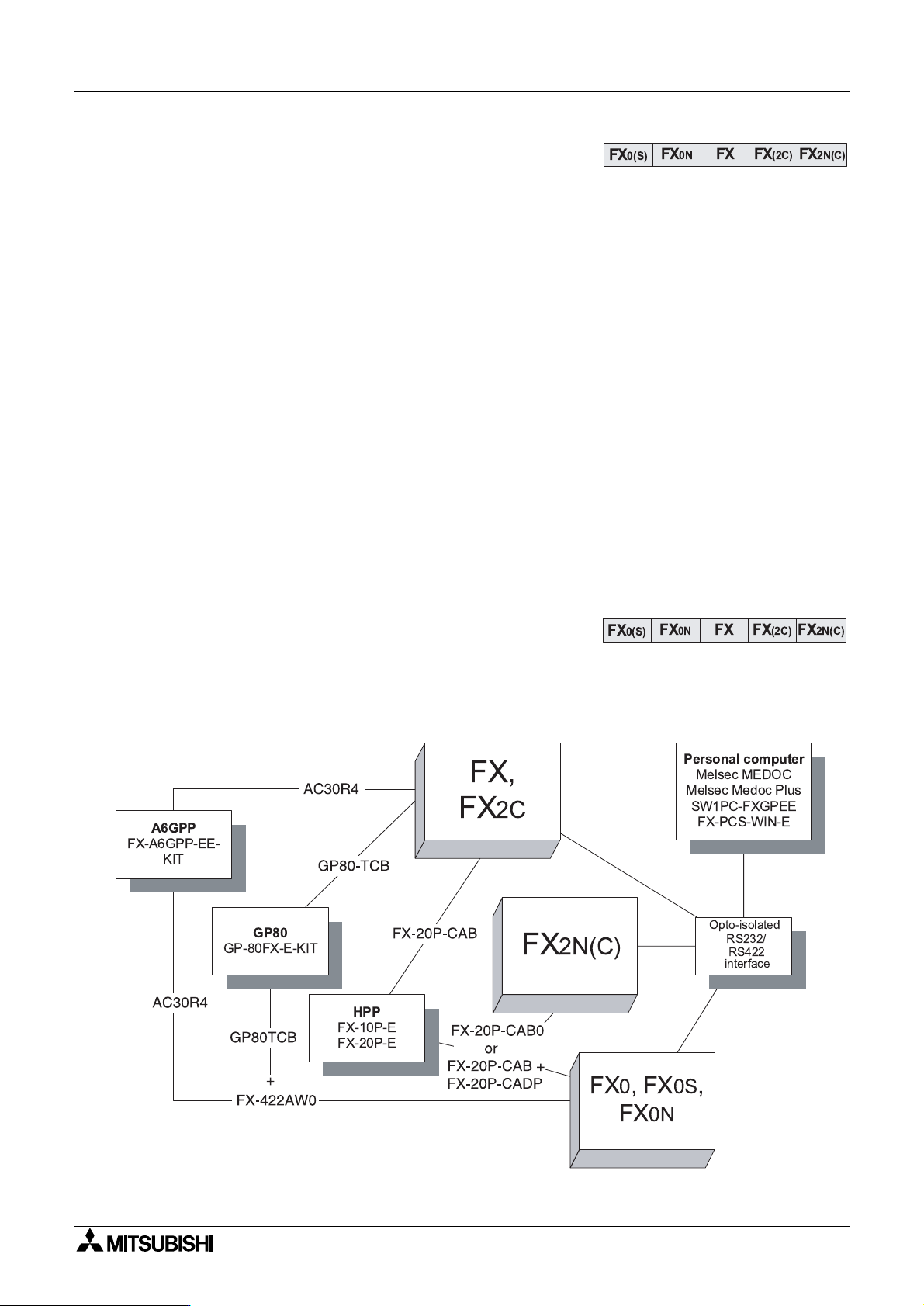
1.3 What do You Need to Program a PLC?
A variety of tools are available to program the Mitsubishi FX family of PLCs. Each of these
tools can use and access the instructions and devices listed in this manual for the identified
PLC.
FX
A6GPP
FX-A6GPP-EE-
KIT
FX,
2C
as todays more advanced products
Personal computer
Melsec MEDOC
Melsec Medoc Plus
SW1PC-FXGPEE
FX-PCS-WIN-E
GP80
GP-80FX-E-KIT
HPP
FX-10P-E
FX-20P-E
FX
2N(C)
Opto-isolated
RS232/
RS422
interface
FX0,FX0S,
FX
0N
1-2

1.4 CPU version numbers
g
g
y
g
g
g
g
y
g
g
FX0(S) FX0N FX FX(2C) FX2N(C)
Over time Mitsubishi adds newer and better features to develop and enhance the products.
Because of the nature of PLCs, that can be likened to ‘industrial computers’, chan
sometimes occur within the units main CPU (Central Processin
similar to those experienced b
processor. The followin
functions and features added.
Introduction 1
es
Unit). These changes are
office and home computer users, that is, going to a version up
lists identify the CPU versions that had significant upgrades or new
1.4.1 FX
0N
CPU versions
CPU Ver 1.20
CPU Ver 1.40
1.4.2 FX and FX
CPU Ver 3.07
The followin
features were added:
Software control for protocol 1 and 4 communications with the FX
1:N network.
The followin
Software control for communications usin
features were added:
the FX0N-485ADP, peer to peer
(N:N) network.
2C
CPU versions
The following instructions were added:
ASCI (FNC82), CCD (FNC84), FLT (FNC49), HEX (FNC83), RS (FNC80),
SER (FNC61), SORT (FNC69), SQR (FNC48)
The following instructions were upgraded:
EI (FNC04), BMOV (FNC15), HSCS (FNC53), PLSY (FNC57),
FMOV (FNC16), MEAN (FNC45), ABSD (FNC62), DSW (FNC72),SEGL (74),
PR (FNC 77)
The following device ranges were added:
Input and output devices are independently addressable upto 256 points in
software. Total combined input and output points (hardware or software) is
256.
Auxiliar
Data re
Optional RAM File Re
relays increased to 1536 points (M0-M1535)
isters increased to 1000 points (D0-D999)
isters added, 2000 points (D6000 -D7999)
Pointers increased to 128 points (P0 - P127)
0N
-485ADP,
CPU Ver 3.11
CPU Ver 3.2
CPU Ver 3.30
The following instructions were added:
PID (FNC88)
The following features were added:
Software control for protocol 4 communications with th e FX-485ADP, 1:N
network.
The following features were added:
Software control for protocol 1 communications with th e FX-485ADP, 1:N
network.
The following instructions were phased out (removed):
ANRD (FNC91), ANWR (FNC92), BLK (FNC97), MCDE (FNC98), MNET
(FNC90)
1-3
1.5 Special considerations for programming equipment
y
y
ying
y
g
g
g
FX
0(S)
FX0N FX FX(2C)
FX
2N(C)
g
g
y
Introduction 1
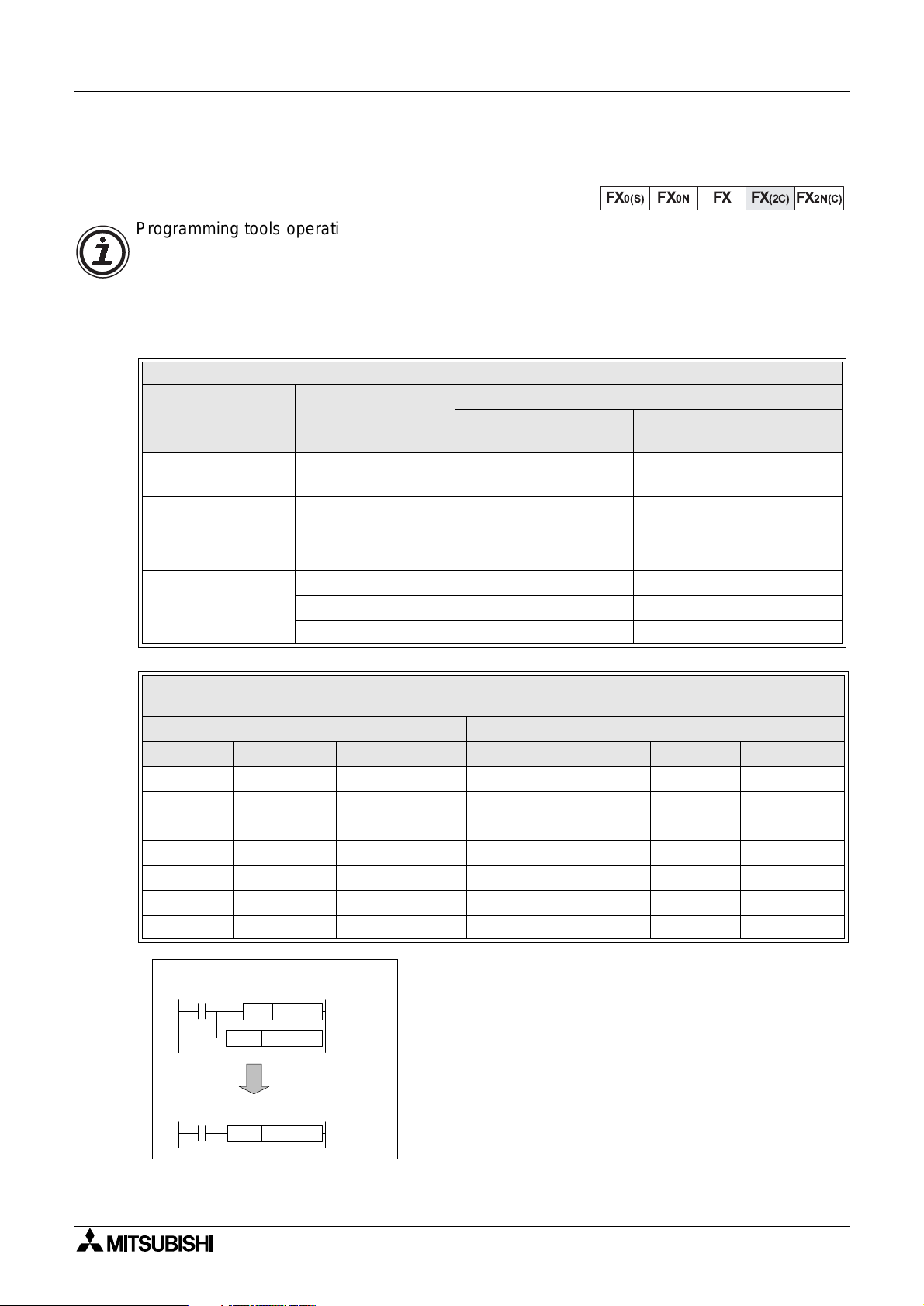
1.5.1 FX CPU version 3.07 or later and FX
Programming tools operating old system software can not access the new featur es added to
the FX CPU from version 3.07 (and available on all FX
certain ‘standard’ applied instructions in conjunction with special auxiliary coils (M coils) can
achieve the same ’effective instruction’ as the new instructions. The followin
which version of peripheral software will work directly with all of the ’new’ features and which
peripheral software versions require use of modified instructions.
Description Model Number
Hand held
pro
rammer (HHP)
HHP cassette FX-20P-MFXA-E V 1.20 from V 2.00
rammin
Pro
software
Data access units
FX-10P-E V 1.10 from V 2.00
FX-PCS/AT-E-KIT V 1.01 from V 2.00
FX-A6GPP-E-KIT V 1.00 from V 2.00
FX-10DU-E V 1.10 from V 2.00
FX-20DU-E V 1.10 from V 2.00
Other DU units from V 1.00
2C
Peripherals Table
System software version which will.......
....require the use of
auxiliary M coils
2C
units). However, programmin
tables identif
....program all instructions
directly
Existing Instruction And Special M Coil Combination To Mimic The Operation Of The
Identified Instruction
Existing FX instruction used to mimic the operation of......
Mnemonic FNC number Modifying M coil Mimicked instruction Mnemonic FNC Number
MOV 12 M8190 Square root SQR 48
MOV 12 M8191 Float FLT 49
RAMP 67 M8193 Data search SER 61
RAMP 67 M8194 RS232 instruction RS 80
FMOV 16 M8196 Hex to ASCII conversion ASCI 82
FMOV 16 M8197 ASCII to Hex conversion HEX 83
FMOV 16 M8195 Sum check CCD 84
Example usage
Using existing FX functions......
SET
M8190
D10
K36
MOV
to mimic......
This format is ver
correctl
.The user must program the ’mimic’ instruction
with the modif
before the instruction to be modified.
important for the instruction to operate
M coil in a SET instruction immediatel
SQR
K36
D10
1-4
Introduction 1
y
y
g
g
g
g
g
g
g
g
g
g
g
FX
0(S)
FX0N FX FX(2C)
FX
2N(C)
g
y
g
Using the new Interrupt Pointers:
To pro
throu
instruction with older pro
ram new Interrupt Pointer s I010
h I060 in to the HSCS (FNC 53)
rammin
equipment, substitute the followin
special M codes for the appropriate
Interrupt Pointer; see the table ri
ht.
Existing Instruction And Special M Coil
Combination To Mimic The Operation
Of The Identified Interrupt pointer
Existing Auxiliary Coil
used to replace the ident i-
fied Interrupt Pointer
M8181 I010
M8182 I020
M8183 I030
M8184 I040
M8185 I050
M8186 I060
Interrupt Pointer
Using M8198 with the BMOV instruction:
With old software and peripherals, file re
BMOV (FNC 15) instruction. To BMOV data into file re
isters can not be used as a destination device in the
isters with old equipment set special M
coil M8198 on. This switches the source and destination parameters; i.e., the source is then
treated as the destination and the destination becomes the source.
General note:
I
pro
sections, will apply.
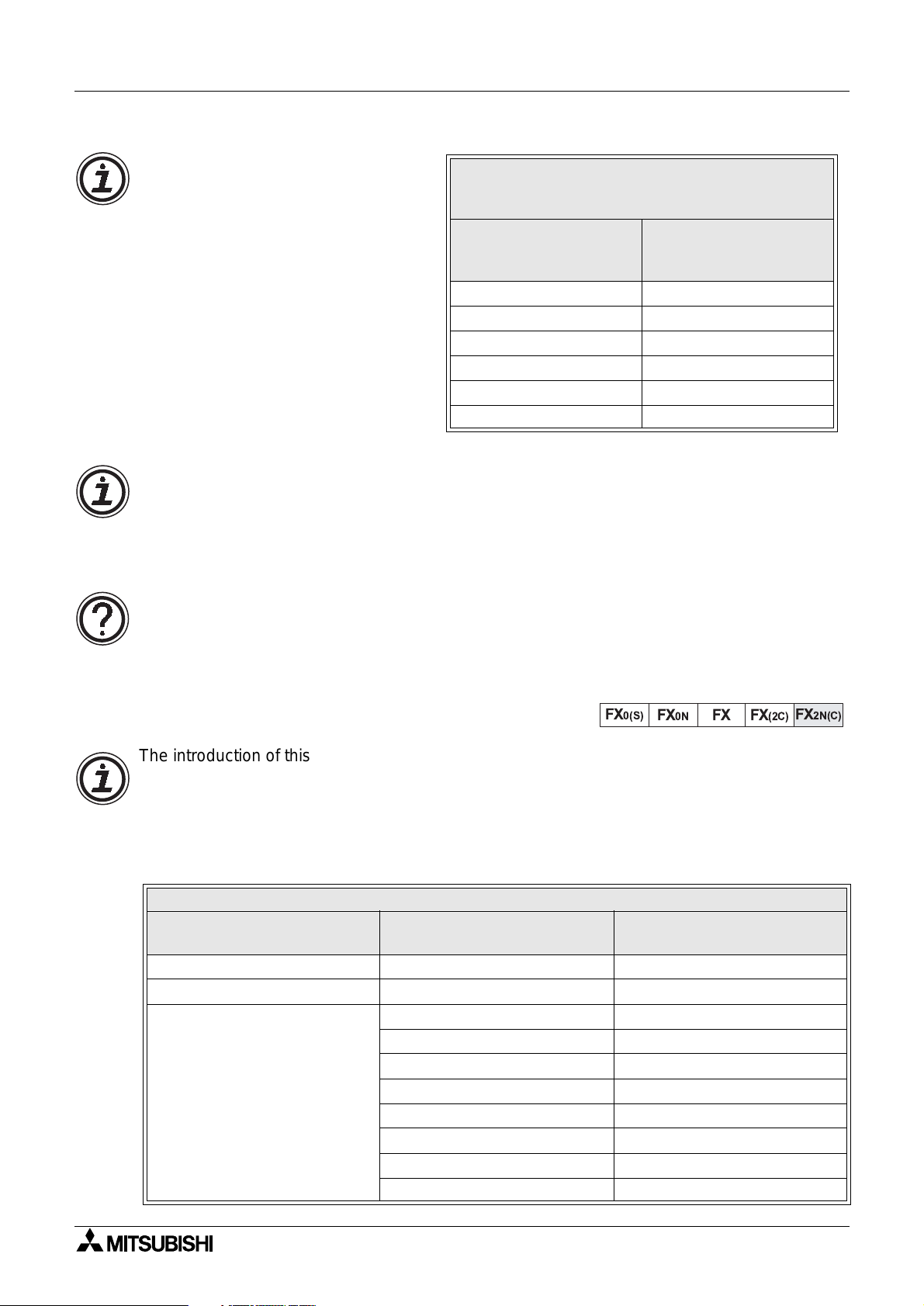
1.5.2 FX
The introduction of this CPU provides the FX user with many new devices and instructions. To
use the full features of the FX
pro
However, because of the downward compatibilit
existin
CPU ver 3.30 units.
nore the special programming techniques identified in this section if using updated
ramming software or peripherals; then normal operation, as identifiedin the followin
2N(C)
CPU all versions
2N(C)
units the user must upgrade older software and hardware
ramming tools.
of the FX
programming tools for use with FX
Description Model Number
Hand held programmer (HHP) FX-10P-E from V 3.00
HHP cassette FX-20P-MFXA-E from V 3.00
FX-10DU-E from V 4.00
FX-20DU-E Supports up to FX devices onl
FX-25DU-E from V 2.00
FX-30DU-E from V 3.00
Data access units
FX-40DU-E(S) Supports up to FX devices onl
FX-40DU-TK-ES from V 3.00
FX-50DU-TK(S)-E from V 2.10
F940GOT-SWD(LWD)-E All versions
2N(C)
units up to the equivalent functionality of FX
Peripherals Table
2N(C)
, it is not necessary to upgrade
System software version with
full support for FX
2N(c)
1-5

MEMO
Introduction 1
1-6
FX Series Programmable Controllers Basic Program Instructions 2
1 Introduction
2 Basic Program Instructions
3 STL Programming
4 Devices in Detail
5 Applied Instructions
6 Diagnostic Devices
7 Instruction Execution Times
8 PLC Device Tables
9 Assigning System Devices
10 Points of Technique
11 Index

FX Series Programmable Controllers Basic Program Instructions 2
g
g
g
g
g
g
g
g
Chapter Contents
2. Basic Pro
ram Instructions ...................................................................2-1
2.1 What is a Program?.... .. ... .. .. .. ... .. .. .... ... .. .. .. .. ... .. .. .. .. ..... .. .. .. ... .. .. .. ... .. .. .... ... .. .. .. .. ...2-1
2.2 Outline of Basic Devices Used in Pro
2.3 How to Read Ladder Lo
ic..................................................................................2-2
ramming..................................................2-1
2.4 Load, Load Inverse ..............................................................................................2-3
2.5 Out.......................................................................................................................2 -4
2.5.1 Timer and Counter Variations ...................................................................................2-4
2.5.2 Double Coil Desi
nation..... ...... ....... ...... ....... ...... ...... ....... ...... ....... ...... ....... ...... ....... ...2-5
2.6 And, And Inverse.................................................................................................2-6
2.7 Or, Or Inverse......................................................................................................2-7
2.8 Load Pulse, Load Trailin
2.9 And Pulse, And Trailin
2.10 Or Pulse, Or Trailin
Pulse. .. .. ................ .. .. ............... ... .. .............................2-8
Pulse.............................................................................2-9
Pulse................................................................................2-10
2.11 Or Block.............................................................................................................2-11
2.12 And Block ..........................................................................................................2-12
2.13 MPS, MRD and MPP......................................... .. .. .. ..........................................2-13
2.14 Master Control and Reset................................................... ...............................2-15
2.15 Set and Reset................. ................................. ................................. .................2-17
2.16 Timer, Counter(Out & Reset)................................................... ..........................2-18
2.16.1 Basic Timers, Retentive Timers And Counters........................................................2-18
2.16.2 Normal 32 bit Counters ...........................................................................................2-19
2.16.3 Hi
h Speed Counters ..............................................................................................2-19
2.17 Leading and Trailing Pulse................................................................................2-20
2.18 Inverse...............................................................................................................2-21
2.19 No Operatio n . .. .. ............................... ... .. ............................... .. .. .........................2-22
2.20 End ....... .. ............................................... .. .. ............................... .. ... ............... .. .. .2 -23
g
g
g
g
g
y
y
y
y
y
g
g
FX Series Programmable Controllers
2. Basic Program Instructions
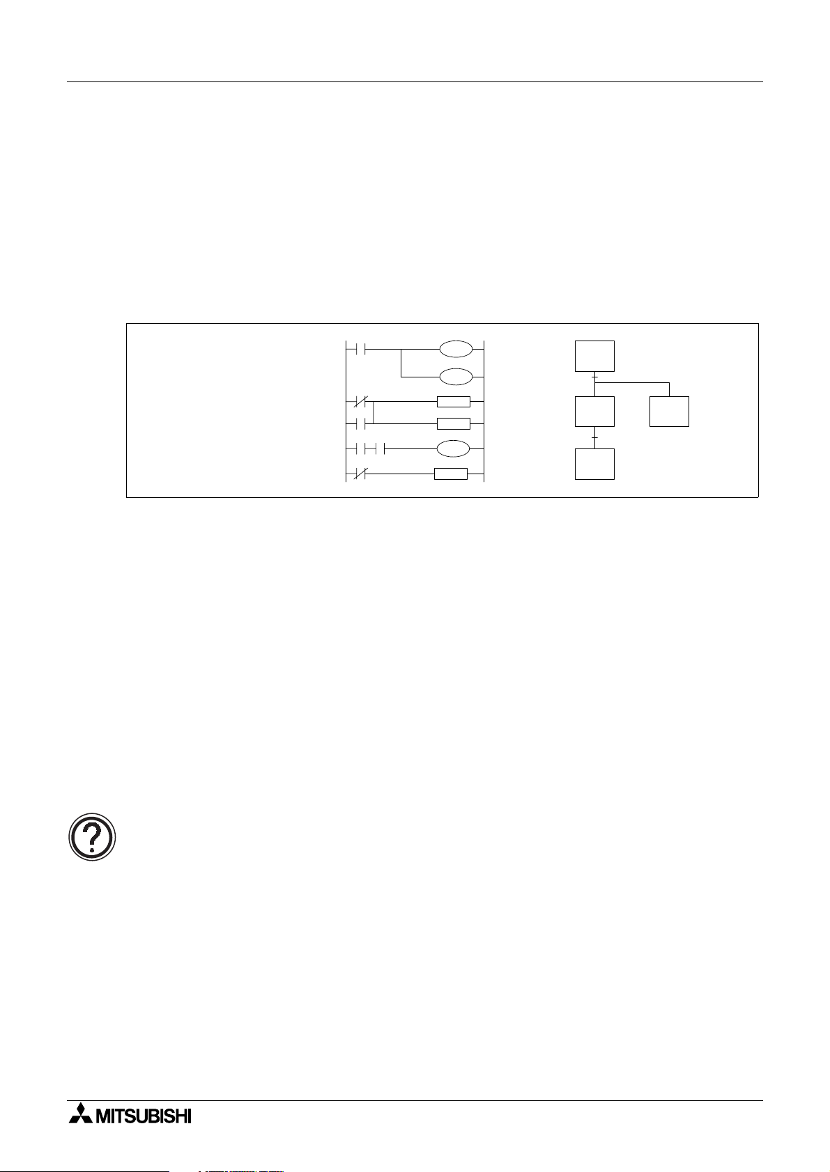
2.1 What is a Program?
A program is a connected series of instructions written in a language that the PLC can
understand. There are three forms of pro
pro
ramming tools can work in all programming forms. Generally hand held programmin
panels only work with instruction format while most graphic programming tools will work with
both instruction and ladder format. Specialist pro
pro
ramming.
Basic Program Instructions 2
ram format; instruction, ladder and SFC/STL. Not all
ramming software will also allow SFC style
LD
OUT
AND
SET
LD
OUT
X10
Y7
M38
S5
X21
T01
K40
Instruction format Ladder Format SFC Format
2.2 Outline of Basic Devices Used in Programming
There are six basic programming devices. Each device has its own unique use. To enable
quick and eas
- X: This is used to identif
- Y: This is used to identif
- T: This is used to identif
- C: This is used to identif
- M and S: These are used as internal operation fla
identification each device is assigned a single reference letter;
all direct, physical inputs to the PLC.
all direct, physical outputs from the PLC.
a timing device which is contained within the PLC.
a counting device which is contained within the PLC.
s within the PLC.
All of the devices mentioned above are known as ‘bit devices’. This is a descriptive title tellin
the user that these devices only have two states; ON or OFF, 1 or 0.
Detailed device information:
• Chapter 4 contains this information in detail. However, the above is all that is
required for the rest of this chapter.
2-1
FX Series Programmable Controllers Basic Program Instructions 2
g
g
y
y
g
g
g
y
y
y
g
g
g
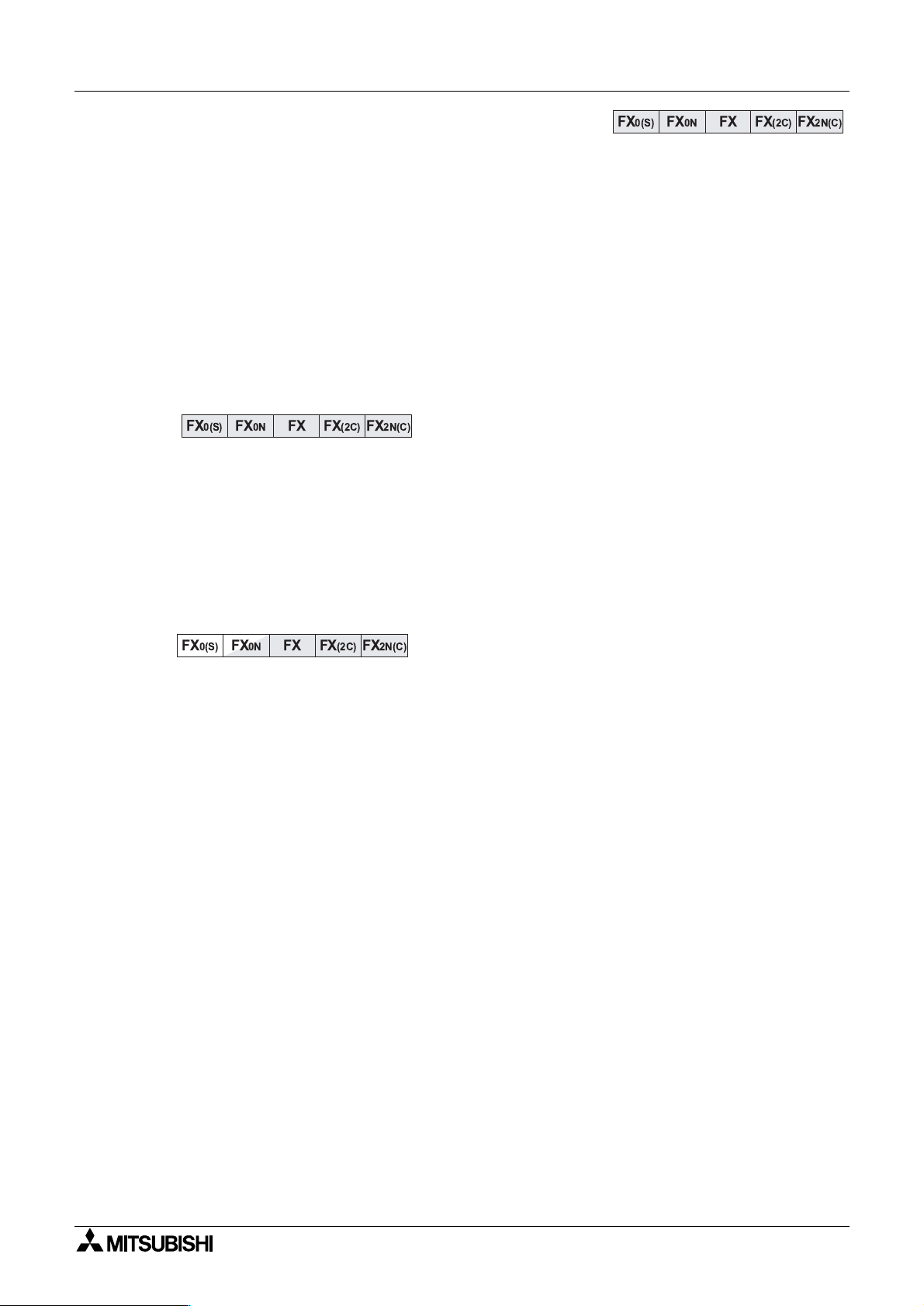
2.3 How to Read Ladder Logic
Ladder logic is very closely associated to basic relay logic. There are both contacts and coils
that can be loaded and driven in different confi
the same.
A coil drives direct outputs of the PLC (ex. a Y device) or drives internal timers, counters or
s (ex. T, C, M and S devices). Each coil has associated contacts. These contacts are
fla
available in both “normall
open” (NO) and “normally closed” (NC) configurations.
urations. However, the basic principle remains
The term “normal(l
)” refers to the status of the contacts when the coil is not energized. Usin
a relay analogy, when the coil is OFF, a NO contact would have no current flow, that is, a load
bein
supplied through a NO contact w ould not o perate. Ho wever, a NC contact w ould allo w
current to flow, hence the connected load would be active.
Activatin
the coil reverses the contact status , that is, the current would flow in a NO contac t
and a NC contact would inhibit the flow.
Ph
sical inputs to the PLC (X devi ces) have n o programmable coil. These devices may only be
used in a contact format (NO and NC t
pes are available).
Example:
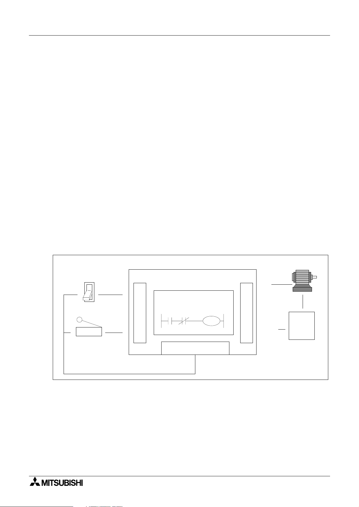
Because of the close rela
association, ladder logic programs can be read as current flowin
from the left ve rtical line to the right vertical line. This current must pass through a series of
contact representations such as X0 and X1 in order to switch the output coil Y0 ON. Therefore,
in the example shown, switchin
X0 ON causes the output Y0 to also switch ON. If however,
the limit switch X1 is activa tes, the output Y0 turns OFF. This is because the con nection
between the left and the ri
Toggle switch
X0
X1
Limit switch
ht vertical lines breaks so there is no current flow.
Programmable Controller
Y0
I
N
P
U
T
PC Program
X0 X1
Y0
DC Power Supply
O
U
T
P
U
COM
T
(Y0)
Motor
AC
Power
Supply
2-2
FX Series Programmable Controllers Basic Program Instructions 2
y
g
g
y
y
g
y
y
g
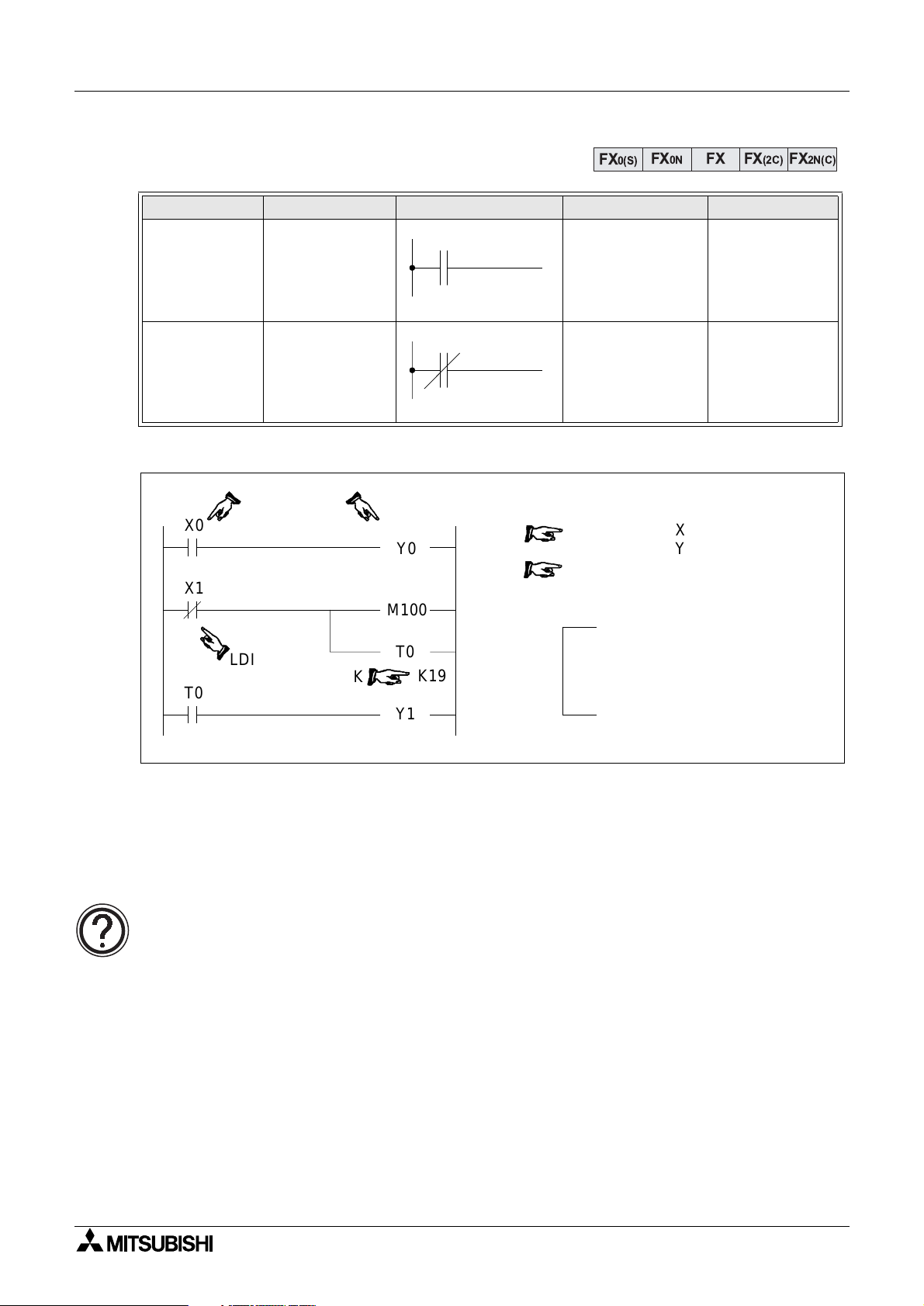
2.4 Load, Load Inverse
Mnemonic Function Format Devices Program steps
Initial lo
LD
(LoaD)
LDI
(LoaD Inverse)
Program example:
X0
X1
T0
operation contact
t
pe NO
(normall
Initial lo
operation contact
t
pe NC
(normall
LDI
ical
open)
ical
closed)
K
Y0
M100
T0
Y1
K19
FX
X, Y, M, S, T, C 1
X, Y, M, S, T, C 1
0
1
2
3
4
7
8
FX0N FX FX(2C)
0(S)
LD
OUT
LDI
OUT
OUT
SP
LD
OUT
X
Y
X
M
T
K
T
Y
100
0
0
1
0
19
0
1
When using hand held
programmers, the space key
needs to be pressed to enable
the constant to be entered.
FX2N(C)
Basic points to remember:
- Connect the LD and LDI instructions directl
- Or use LD and LDI instructions to define a new block of pro
to the left hand bus bar.
ram when using the ORB
and ANB instructions (see later sections).
The OUT instruction:
• For details of the OUT instruction (including basic timer and counter variations)
please see over the followin
page.
2-3
FX Series Programmable Controllers Basic Program Instructions 2
y
y
g
g
y
g
y
gg
g
g
y
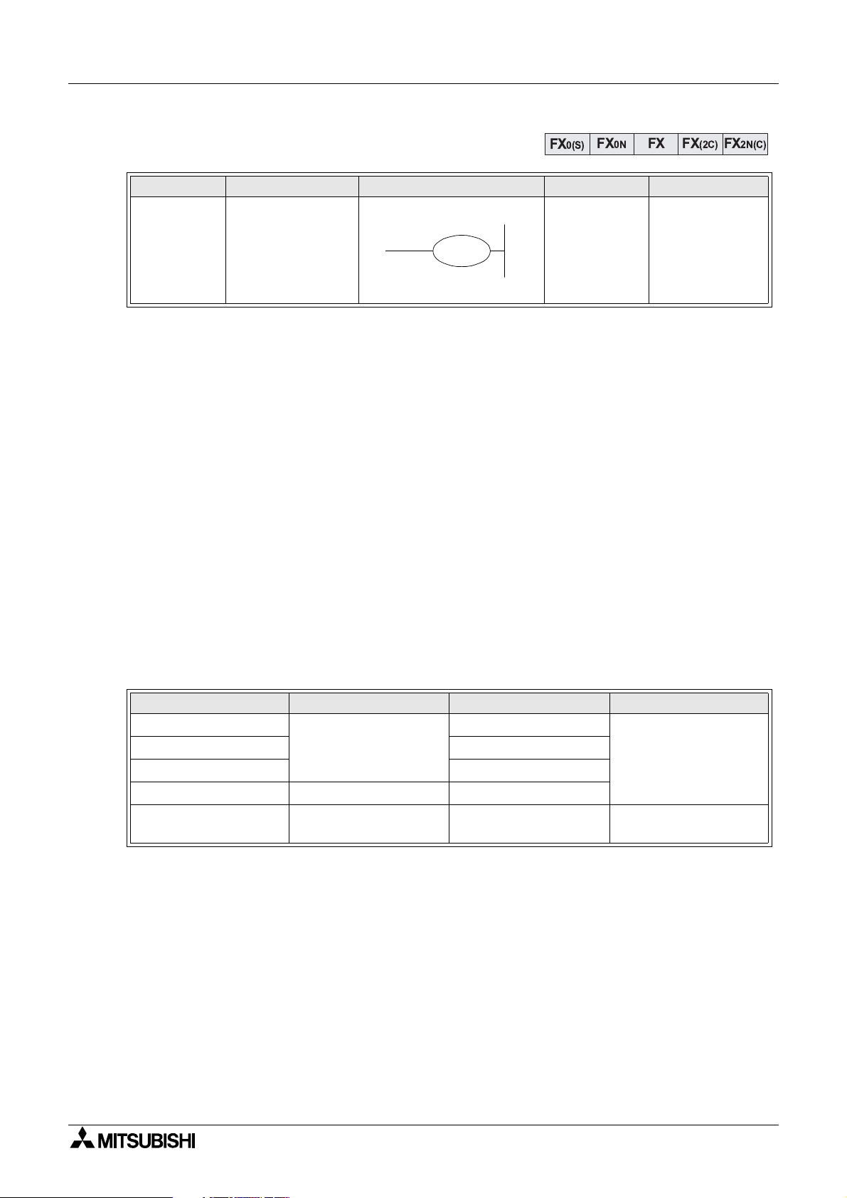
2.5 Out
Mnemonic Function Format Devices Program steps
OUT
(OUT)
Final lo
operation t
drive
Basic points to remember:
- Connect the OUT instruction directl
- It is not possible to use the OUT instruction to drive ‘X’ t
- It is possible to connect multiple OUT instructions in parallel (for example see the
previous pa
2.5.1 Timer and Counter Variations
When confi
uring the OUT instruction for u se as either a timer (T) or counte r (C) a consta nt
must also be entered. The constant is identified b
pa
e; T0 K19).
In the case of a timer, the constant “K” holds the duration data for the timer to operate, i.e. if a
100 msec timer has a constant o f “K100” it will be (100 5 100 msec) 10 s econds before the
timer coil activates.
With counters, the constant identifi es how ma n
before the counter coil activates. For example, a counter with a constant of “8” must be
tri
ered 8 times before the counter coil finally energizes.
The followin
table identifies some basic parameter data for various timers and counters;
ical
pe coil
e; M100/T0 configuration)
FX
Y, M, S, T, C
FX0N FX FX(2C)
0(S)
Y, M:1
S, special M
coils: 2
T:3
C (16 bit): 3
C (32 bit): 5
to the right hand bus bar.
pe input devices.
the letter “K” (for example see previous
times the counter must be pulsed or triggered
FX2N(C)
Timer/Counter Setting constant K Actual setting Program steps
1 msec Timer
10 msec Timer 0.01 to 327.67 sec
100 msec Timer 0.1 to 3276.7 sec
16 bit Counter 1 to 32,767 1 to 32,767
32 bit Counter
1 to 32,767
-2,147,483,648 to
2,147,483,647
0.001 to 32.767 sec
-2,147,483,648 to
2,147,483,647
3
5
2-4
Loading...