


 Loading...
Linksys SPA9000 Administrator Guide
Version 3.0
Corporate Headquarters
Linksys
121 Theory Drive
Irvine, CA 92617 USA
http://www.linksys.com Tel: 949 823-1200
800 546-5797 Fax: 949 823-1100
Specifications are subject to change without notice. Linksys is a registered trademark or trademark of Cisco Systems, Inc. and/or its affiliates in the U.S. and certain other countries. Other brands and product names are trademarks or registered trademarks of their respective holders.
Linksys SPA9000 Administrator Guide
Copyright ©2006 Cisco Systems, Inc. All rights reserved.

C O N T E N T S
|
|
Preface xi |
|
|
|
|
|
|
|
|
|
|
|
Document Audience |
xi |
|
|
|
|
|
|
|
|
|
|
How This Document is Organized |
xii |
|
|
|
|
|
|||
|
|
Document Conventions |
xii |
|
|
|
|
|
|
|
|
|
|
Related Documentation |
xiii |
|
|
|
|
|
|
||
|
|
Technical Support |
xiii |
|
|
|
|
|
|
|
|
|
Using the Linksys Voice System |
|
|
|
|
|
|
||||
C H A P T E R 1 |
1-1 |
|
|
|
|
|
|||||
|
|
The Linksys Voice System |
1-1 |
|
|
|
|
|
|
||
|
|
Overview 1-1 |
|
|
|
|
|
|
|
|
|
|
|
SPA400 SIP-PSTN Gateway and Voicemail |
1-2 |
|
|
|
|||||
|
|
Auto-Attendant 1-3 |
|
|
|
|
|
|
|
||
|
|
SPA9000 System Features |
1-3 |
|
|
|
|
|
|||
|
|
Additional Features When Used with SPA900 Series IP Phones 1-5 |
|||||||||
|
|
Technology Background |
1-6 |
|
|
|
|
|
|
||
|
|
Session Initiation Protocol |
1-6 |
|
|
|
|
|
|||
|
|
SPA9000 Media Proxy |
1-7 |
|
|
|
|
|
|
||
|
|
Using the SPA9000 with a Firewall or Router |
1-8 |
|
|
|
|||||
|
|
SPA400 SIP-PSTN Gateway |
1-8 |
|
|
|
|
|
|||
|
|
Network Address Translation (NAT) 1-9 |
|
|
|
|
|||||
|
|
NAT Overview |
1-9 |
|
|
|
|
|
|
||
|
|
NAT Types |
1-10 |
|
|
|
|
|
|
|
|
|
|
Simple Traversal of UDP Through NAT |
1-10 |
|
|
|
|||||
|
|
SIP-NAT Interoperation |
1-11 |
|
|
|
|
|
|||
|
|
SPA9000 Architecture |
1-11 |
|
|
|
|
|
|
||
|
|
Architectural Components |
1-12 |
|
|
|
|
|
|||
|
|
Multicast Addressing and Group Paging 1-13 |
|||||||||
|
|
Configuration Options |
1-14 |
|
|
|
|
|
|
||
|
|
Interactive Voice Response |
1-14 |
|
|
|
|
||||
|
|
Setup Wizard |
1-14 |
|
|
|
|
|
|
||
|
|
Administration Web Server |
1-14 |
|
|
|
|
||||
|
|
Local Client Configuration and Registration 1-15 |
|||||||||
|
|
|
|
|
|
|
|
Linksys SPA9000 Administrator Guide |
|
|
|
|
|
|
|
|
|
|
|
|
|||
|
Version 3.0 |
|
|
|
|
|
|
|
|
iii |
|
|
|
|
|
|
|
|
|
|
|
||

|
|
|
|
|
|
|
|
|
|
|
|
|
|
|
|
|
|
|
|
|
|
|
|
|
|
|
|
|
|
|
|
|
|
|
|
|
|
|
|
|
|
|
|
|
|
|
|
|
|
Contents |
|
|
|
|
|
|
|
|
|
|
|
||
|
|
|
|
|
|
Remote Provisioning of the SPA9000 |
1-15 |
|
|||||||
|
|
|
|
|
|
Where to Go From Here |
1-16 |
|
|
|
|
|
|
||
|
|
|
Getting Started 6-1 |
|
|
|
|
|
|
|
|
||||
|
C H A P T E R 2 |
|
|
|
|
|
|
|
|
|
|||||
|
|
|
|
|
|
Implementing LVS |
6-1 |
|
|
|
|
|
|
|
|
|
|
|
|
|
|
Using the SPA9000 and SPA400 as a VoIP PBX System 6-2 |
|
||||||||
|
|
|
|
|
|
Using the SPA9000 as a Media Proxy |
6-3 |
|
|
||||||
|
|
|
|
|
|
Using the LVS as a Key System |
|
6-3 |
|
|
|
||||
|
|
|
|
|
|
SPA9000 Hardware |
6-4 |
|
|
|
|
|
|
||
|
|
|
|
|
|
SPA9000 Back Panel |
6-5 |
|
|
|
|
|
|||
|
|
|
|
|
|
The Front Panel |
6-5 |
|
|
|
|
|
|
||
|
|
|
|
|
|
SPA400 Hardware |
6-6 |
|
|
|
|
|
|
||
|
|
|
|
|
|
Bandwidth Requirements |
6-6 |
|
|
|
|
|
|||
|
|
|
|
|
|
Caring for Your Hardware |
6-7 |
|
|
|
|
|
|||
|
|
|
|
|
|
Making the Physical Connections |
6-8 |
|
|
|
|||||
|
|
|
|
|
|
Using the Interactive Voice Response Interface |
6-9 |
|
|||||||
|
|
|
|
|
|
Using the IVR Menu |
6-9 |
|
|
|
|
|
|
||
|
|
|
|
|
|
IVR Options |
6-10 |
|
|
|
|
|
|
|
|
|
|
|
|
|
|
Entering a Password through the IVR |
6-12 |
|
|
||||||
|
|
|
|
|
|
Initial Setup and Configuration |
6-13 |
|
|
|
|
||||
|
|
|
|
|
|
Licensing |
6-13 |
|
|
|
|
|
|
|
|
|
|
|
|
|
|
Using DHCP or Static IP Addressing 6-13 |
|
|
|||||||
|
|
|
|
|
|
Using the Wizard for Initial Configuration |
6-14 |
|
|||||||
|
|
|
|
|
|
Using the Wizard to Upgrade Software |
6-19 |
|
|||||||
|
|
|
|
|
|
Setting the SPA9000 Administrator Account Password 6-22 |
|
||||||||
|
|
|
|
|
|
Using the Administration Web Server |
6-23 |
|
|
|
|||||
|
|
|
|
|
|
Connecting to the Administration Web Server 6-23 |
|
||||||||
|
|
|
|
|
|
Administrator Account Privileges |
6-25 |
|
|
|
|||||
|
|
|
|
|
|
Advanced Methods of Configuration |
6-26 |
|
|
|
|||||
|
|
|
|
|
|
Web Interface URLs |
6-26 |
|
|
|
|
|
|
||
|
|
|
|
|
|
Upgrade URL |
6-26 |
|
|
|
|
|
|
||
|
|
|
|
|
|
Resync URL |
6-26 |
|
|
|
|
|
|
||
|
|
|
|
|
|
Reboot URL |
6-27 |
|
|
|
|
|
|
||
|
|
|
|
|
|
Provisioning |
6-27 |
|
|
|
|
|
|
|
|
|
|
|
|
|
|
Provisioning Capabilities |
6-27 |
|
|
|
|||||
|
|
|
|
|
|
Configuration Profile |
6-28 |
|
|
|
|
||||
|
|
|
|
|
|
Client Auto-Configuration |
6-29 |
|
|
|
|
||||
|
|
|
|
|
|
Manual Client Configuration |
6-30 |
|
|
|
|||||
|
|
|
|
|
|
Client Registration |
6-32 |
|
|
|
|
|
|
||
|
|
|
|
|
Linksys SPA9000 Administrator Guide |
|
|
|
|
|
|
|
|
|
|
|
|
|
|
|
|
|
|
|
|
|
|
|
|
||
|
|
iv |
|
|
|
|
|
|
|
|
|
|
|
Version 3.0 |
|
|
|
|
|
|
|
|
|
|
|
|
|
|
|||

|
|
|
|
|
|
|
|
|
|
|
|
|
|
|
|
|
|
|
|
|
|
|
|
|
|
Contents |
|
|
Troubleshooting and Configuration FAQ |
6-33 |
|
|
|
|
|
Configuring Voice Service and Voicemail |
|
|
|
|
|
C H A P T E R 3 |
3-1 |
|
|
|
|
|
|
Using the Wizard to Configure ITSP Voice Services and Voicemail |
3-1 |
|
|
||
|
Completing the Voicemail Configuration |
3-6 |
|
|
|
|
|
Configuring the SPA400 for PSTN Connectivity or Voicemail |
3-8 |
|
|
|
|
|
Understanding How the SPA400 Interacts with the SPA9000 |
3-8 |
|
|
||
|
Using the SPA9000 Setup Wizard to Configure the SPA400 3-8 |
|
||||
|
Using the Administration Web Server to Configure the SPA400 |
3-11 |
|
|
||
|
Accessing the Administration Web Server 3-12 |
|
|
|
|
|
|
Configuring the SPA400 to Connect to the SPA9000 |
3-12 |
|
|
|
|
|
Configuring the SPA9000 to Register the SPA400 |
3-15 |
|
|
|
|
|
|
Configuring the SPA400 Voicemail Services |
3-15 |
|
|
|
|||||
|
|
Configuring the SPA9000 Voicemail Settings |
3-16 |
|
|
|
|||||
|
|
Configuring SPA400 Voicemail Accounts |
3-17 |
|
|
|
|||||
|
|
Configuring a SPA IP Phone for Voice Mail Service |
3-18 |
|
|
|
|||||
|
|
SPA400 Voicemail Options |
3-20 |
|
|
|
|
|
|
||
|
|
Managing Voicemail |
3-20 |
|
|
|
|
|
|
|
|
|
|
How Voicemail Works |
3-21 |
|
|
|
|
|
|
||
|
|
Checking Voicemail from an External Number |
3-22 |
|
|
|
|||||
|
|
Depositing Voicemail |
3-22 |
|
|
|
|
|
|
||
|
|
Subscribing to Voicemail Notification |
3-23 |
|
|
|
|
||||
|
Configuring SPA9000 Features |
|
|
|
|
|
|
|
|||
C H A P T E R 4 |
4-1 |
|
|
|
|
|
|
||||
|
|
Using the Wizard to Configure SPA9000 Voice Features 4-1 |
|||||||||
|
|
Configuring Client Stations |
4-2 |
|
|
|
|
|
|||
|
|
Configuring Client Extensions |
4-4 |
|
|
|
|
|
|||
|
|
Configuring Shared Extensions |
4-5 |
|
|
|
|
|
|||
|
|
Configuring a Call Hunt Group |
4-6 |
|
|
|
|
|
|||
|
|
Using the Wizard for Localization 4-7 |
|
|
|
|
|
||||
|
|
Using Dial Plans 4-9 |
|
|
|
|
|
|
|
|
|
|
|
Configuring Dial Plans |
4-9 |
|
|
|
|
|
|
||
|
|
Dial Plan Digit Sequences |
4-9 |
|
|
|
|
|
|||
|
|
Dial Plan Rules |
4-10 |
|
|
|
|
|
|
|
|
|
|
Dial Plan Examples |
4-11 |
|
|
|
|
|
|
|
|
|
|
Dial Plan Timers |
4-12 |
|
|
|
|
|
|
|
|
|
|
Interdigit Long Timer |
4-12 |
|
|
|
|
|
|
||
|
|
Interdigit Short Timer |
4-12 |
|
|
|
|
|
|||
|
|
|
|
|
|
|
|
Linksys SPA9000 Administrator Guide |
|
|
|
|
|
|
|
|
|
|
|
|
|||
|
Version 3.0 |
|
|
|
|
|
|
|
|
v |
|
|
|
|
|
|
|
|
|
|
|
||

Contents
Dial Plans |
4-13 |
|
|
|
|
||
Basic Call Management |
4-13 |
|
|
|
|||
Receiving External Phone Calls |
4-13 |
|
|
||||
Calling Between Client Stations |
4-13 |
|
|||||
Client Stations Calling an External Number |
4-14 |
||||||
External Users Calling the SPA9000 |
4-15 |
|
|||||
Supporting Multiple DID Numbers Per Line Interface 4-16 |
|||||||
Managing Call Forwarding |
4-17 |
|
|
|
|||
How Call Forwarding Works 4-17 |
|
|
|||||
Using Call Hunt Groups |
4-19 |
|
|
|
|||
Overview |
4-19 |
|
|
|
|
||
Configuring a Hunt Group Rule |
4-19 |
|
|||||
Using the Contact List Parameter |
4-20 |
|
|||||
Using the Administration Web Server to Configure Hunt Groups 4-21 |
|||||||
Client Station Blind Transfers External Caller To DID/Hunt Group 4-22 |
|||||||
Using Shared Line Appearance |
4-22 |
|
|
||||
Managing Call Pickup |
4-25 |
|
|
|
|
||
Directed Call Pickup |
4-25 |
|
|
|
|||
Group Call Pickup |
4-26 |
|
|
|
|
||
Call Park and Pickup |
4-26 |
|
|
|
|||
Multicast and Group Paging |
4-27 |
|
|
|
|||
Music On Hold |
4-29 |
|
|
|
|
|
|
Overview |
4-29 |
|
|
|
|
|
|
Changing the Internal Music Source |
4-29 |
|
|||||
Restoring the Default Internal Music Source |
4-30 |
||||||
Using a Streaming Audio Server |
4-31 |
|
|||||
Using the IVR with an SAS Line |
4-31 |
|
|||||
Example SAS with MOH |
4-32 |
|
|
|
|||
Configuring the Streaming Audio Server 4-32 |
|||||||
Enhancements in Release 5.1 |
4-33 |
|
|
|
|||
Bridge Mode |
4-33 |
|
|
|
|
|
|
Call Forward Bridge Mode |
4-33 |
|
|
||||
Call Transfer Bridge Mode |
4-34 |
|
|
||||
REGISTER Enhancement |
4-34 |
|
|
|
|||
Renew DHCP On SIP Request Timeout |
4-35 |
|
|||||
Linksys SPA9000 Administrator Guide
|
vi |
Version 3.0 |
|
|
|

|
|
|
|
|
|
|
|
|
|
|
|
|
|
|
|
|
|
|
|
|
|
|
|
|
|
|
|
|
|
|
|
|
|
|
|
|
|
|
|
|
|
|
|
|
|
|
|
|
|
|
|
|
|
|
|
|
|
|
|
|
|
|
|
|
Contents |
|
|
|
|
Configuring the LVS Auto-Attendant |
|
|
|
|
|
|
|
|
||||||
C H A P T E R |
5 |
5-1 |
|
|
|
|
|
|
|
|||||||
|
|
|
Configuring Auto-Attendant |
5-1 |
|
|
|
|
|
|
|
|
||||
|
|
|
How the Auto-Attendant Works |
5-1 |
|
|
|
|
|
|
|
|||||
|
|
|
Using the IVR to Record Auto-Attendant Prompts |
5-2 |
|
|
|
|
||||||||
|
|
|
Using the Wizard to Configure the Auto-Attendant |
5-4 |
|
|
|
|
||||||||
|
|
|
Using the Administration Web Server to Configure the Auto-Attendant 5-6 |
|
||||||||||||
|
|
|
Downloading Prompts |
|
5-8 |
|
|
|
|
|
|
|
|
|
|
|
|
|
|
Configuring Dial Plans for the Auto-Attendant 5-9 |
|
|
|
|
|
|
|||||||
|
|
|
Alternative AA Configuration |
|
5-10 |
|
|
|
|
|
|
|
|
|||
|
|
|
Switching Between Alternative AAs Using the IVR |
5-10 |
|
|
|
|
||||||||
|
|
|
XML Scripting for the Auto-Attendant |
5-13 |
|
|
|
|
|
|
||||||
|
|
|
Overview |
5-13 |
|
|
|
|
|
|
|
|
|
|
|
|
|
|
|
XML Scripting Grammar |
|
5-13 |
|
|
|
|
|
|
|
|
|||
|
|
|
Node Type Dialog |
5-14 |
|
|
|
|
|
|
|
|
||||
|
|
|
Menu Type Dialog |
5-14 |
|
|
|
|
|
|
|
|
||||
|
|
|
Dialplan Statement |
|
5-14 |
|
|
|
|
|
|
|
|
|||
|
|
|
AA Instructions |
5-15 |
|
|
|
|
|
|
|
|
|
|
||
|
|
|
Audio Instruction |
5-15 |
|
|
|
|
|
|
|
|
||||
|
|
|
Action Instruction |
5-15 |
|
|
|
|
|
|
|
|
||||
|
|
|
Noinput Instruction |
|
5-15 |
|
|
|
|
|
|
|
|
|||
|
|
|
Nomatch Instruction |
5-16 |
|
|
|
|
|
|
|
|
||||
|
|
|
Menu Matched Instruction—Recognition of Touch Tone (DMTP) Key Presses 5-16 |
|
||||||||||||
|
|
|
AA XML Script Examples |
5-17 |
|
|
|
|
|
|
|
|
||||
|
|
|
Example 1—AA Default XML Script |
5-17 |
|
|
|
|
|
|
||||||
|
|
|
Example 2 |
5-18 |
|
|
|
|
|
|
|
|
|
|
|
|
|
|
|
Example 3—AA Script with Two Treatments |
5-19 |
|
|
|
|
|
|||||||
|
|
|
Office Hour AA Treatment |
5-19 |
|
|
|
|
|
|
|
|||||
|
|
|
Non-Office Hour AA Treatment |
5-20 |
|
|
|
|
|
|
||||||
|
|
|
Auto-Attendant XML Instructions Set |
5-22 |
|
|
|
|
|
|
||||||
|
|
SPA9000 Field Reference |
|
|
|
|
|
|
|
|
|
|
||||
C H A P T E R |
6 |
6-1 |
|
|
|
|
|
|
|
|
|
|||||
|
|
|
Info Tab 6-2 |
|
|
|
|
|
|
|
|
|
|
|
|
|
|
|
|
Product Information |
6-2 |
|
|
|
|
|
|
|
|
|
|||
|
|
|
System Status |
6-2 |
|
|
|
|
|
|
|
|
|
|
|
|
|
|
|
FXS 1/2 Status |
6-3 |
|
|
|
|
|
|
|
|
|
|
||
|
|
|
Line 1/2/3/4 Status (9000) |
6-4 |
|
|
|
|
|
|
|
|
||||
|
|
|
Auto Attendant Prompt Status |
6-4 |
|
|
|
|
|
|
|
|||||
|
|
|
Internal Music Status |
6-5 |
|
|
|
|
|
|
|
|
||||
|
|
|
|
|
|
|
|
|
|
|
|
Linksys SPA9000 Administrator Guide |
|
|
|
|
|
|
|
|
|
|
|
|
|
|
|
|
|
|
|||
|
Version 3.0 |
|
|
|
|
|
|
|
|
|
|
|
|
vii |
|
|
|
|
|
|
|
|
|
|
|
|
|
|
|
|
|||

|
|
|
|
|
|
|
|
|
|
|
|
|
|
|
|
|
|
|
|
|
|
|
|
|
|
|
|
|
|
|
|
|
|
|
|
|
|
|
|
|
|
|
|
|
|
|
Contents |
|
|
|
|
|
|
|
|
|
|
||
|
|
|
|
System Tab |
6-5 |
|
|
|
|
|
|
|
|
|
|
|
|
|
System Configuration |
|
6-5 |
|
|
|
|
|
|||
|
|
|
|
Miscellaneous Settings 6-6 |
|
|
|
|
||||||
|
|
|
|
SIP Tab 6-7 |
|
|
|
|
|
|
|
|
|
|
|
|
|
|
SIP Parameters |
6-7 |
|
|
|
|
|
|
|
||
|
|
|
|
SIP Timer Values (sec) |
6-8 |
|
|
|
|
|||||
|
|
|
|
Response Status Code Handling |
|
6-10 |
|
|
||||||
|
|
|
|
RTP Parameters |
6-10 |
|
|
|
|
|
|
|||
|
|
|
|
SDP Payload Types |
6-11 |
|
|
|
|
|
||||
|
|
|
|
NAT Support Parameters |
6-13 |
|
|
|
|
|||||
|
|
|
|
PBX Parameters |
6-14 |
|
|
|
|
|
||||
|
|
|
|
Internal Music Source Parameters |
6-17 |
|
||||||||
|
|
|
|
Auto Attendant Parameters |
6-18 |
|
|
|
||||||
|
|
|
|
PBX Phone Parameters |
6-21 |
|
|
|
|
|||||
|
|
|
|
Regional Tab |
6-23 |
|
|
|
|
|
|
|
|
|
|
|
|
|
Call Progress Tones |
|
6-23 |
|
|
|
|
|
|||
|
|
|
|
Distinctive Ring Patterns |
6-25 |
|
|
|
|
|||||
|
|
|
|
Distinctive Call Waiting Tone Patterns |
6-26 |
|
||||||||
|
|
|
|
Distinctive Ring/CWT Pattern Names |
6-26 |
|
||||||||
|
|
|
|
Ring and Call Waiting Tone Spec |
|
6-27 |
|
|
||||||
|
|
|
|
Control Timer Values (sec) |
6-28 |
|
|
|
|
|||||
|
|
|
|
Vertical Service Activation Codes |
6-29 |
|
|
|||||||
|
|
|
|
Vertical Service Announcement Codes |
6-34 |
|
||||||||
|
|
|
|
Outbound Call Codec Selection Codes |
6-35 |
|
||||||||
|
|
|
|
Miscellaneous |
|
6-36 |
|
|
|
|
|
|
|
|
|
|
|
|
FXS 1/2 Tab (SPA9000) |
6-39 |
|
|
|
|
|
||||
|
|
|
|
Line Enable |
6-39 |
|
|
|
|
|
|
|
||
|
|
|
|
Network Settings |
6-39 |
|
|
|
|
|
||||
|
|
|
|
SIP Settings |
6-40 |
|
|
|
|
|
|
|
||
|
|
|
|
Subscriber Information |
6-42 |
|
|
|
|
|||||
|
|
|
|
Dial Plan |
6-42 |
|
|
|
|
|
|
|
|
|
|
|
|
|
Mailbox Status |
6-42 |
|
|
|
|
|
|
|||
|
|
|
|
Streaming Audio Server (SAS) |
6-43 |
|
|
|||||||
|
|
|
|
Call Feature Settings |
|
6-44 |
|
|
|
|
||||
|
|
|
|
Audio Configuration |
|
6-44 |
|
|
|
|
|
|||
|
|
|
|
FXS Port Polarity Configuration |
6-47 |
|
|
|||||||
|
|
|
|
Line 1/2/3/4 Tab |
6-48 |
|
|
|
|
|
|
|
||
|
|
|
|
Line Enable |
6-48 |
|
|
|
|
|
|
|
||
|
|
|
|
Network Settings |
6-48 |
|
|
|
|
|
||||
|
|
|
|
Linksys SPA9000 Administrator Guide |
|
|
|
|
|
|
|
|
|
|
|
|
|
|
|
|
|
|
|
|
|
|
|
||
|
|
viii |
|
|
|
|
|
|
|
|
|
|
Version 3.0 |
|
|
|
|
|
|
|
|
|
|
|
|
|
|||

Contents
|
|
SIP Settings |
6-49 |
|
|
|
Subscriber Information |
6-51 |
|
|
|
Dial Plan 6-53 |
|
|
|
|
NAT Settings |
6-55 |
|
|
|
Proxy and Registration |
6-55 |
|
|
|
Acronyms |
|
|
A P P E N D I X |
A |
|
|
|
|
|
Glossary |
|
|
A P P E N D I X |
B |
|
|
|
|
|
|
|
|
I N D E X |
|
|
|
|
Linksys SPA9000 Administrator Guide
|
Version 3.0 |
ix |
|

Contents
Linksys SPA9000 Administrator Guide
|
x |
Version 3.0 |
|
|
|
Preface
The LVS 9000 solution includes a line of IP communication products including desktop IP phones, an IP PBX, and PSTN gateway
This guide describes basic administration and use of the Linksys SPA9000 IP PBX and the SPA400 PSTN gateway. It contains the following sections:
•Document Audience, page xi
•How This Document is Organized, page xii
•Document Conventions, page xii
•Related Documentation, page xiii
Document Audience
This document is written for the following audience:
•Service providers offering services using LVS products
•VARs and resellers who need LVS configuration references
•System administrators or anyone who performs LVS installation and administration
Note This guide does not provide the configuration information required by specific service providers. Please consult with the service provider for specific service parameters.
Linksys SPA9000 Administrator Guide
|
Version 3.0 |
xi |
|

Preface
How This Document is Organized
How This Document is Organized
This document is divided into the following chapters and appendices.
Chapter |
Contents |
|
|
Chapter 1, “Using the Linksys |
This chapter introduces the SPA9000 IP PBX and the SPA400 PSTN |
Voice System.” |
gateway. |
|
|
Chapter 2, “Getting Started.” |
This chapter describes how to establish connectivity between the |
|
SPA9000, the SPA400, and other components. |
|
|
Chapter 3, “Configuring Voice |
This chapter describes how to configure voice services and SPA400 |
Service and Voicemail.” |
or ITSP-hosted voicemail. |
|
|
Chapter 4, “Configuring |
This chapter describes how to configure SPA9000 features. |
SPA9000 Features.” |
|
|
|
Chapter 5, “Configuring the LVS |
This chapter describes how to configure or write XML scripts for |
Auto-Attendant.” |
the Auto-Attendant |
|
|
Chapter 6, “SPA9000 Field |
This chapter lists the function and usage for each field or parameter |
Reference” |
on the SPA9000 administration web server pages. |
|
|
Appendix A “Acronyms.” |
This appendix provides the expansion of acronyms used in this |
|
document. |
|
|
Appendix B “Glossary.” |
This appendix defines the terms used in this document. |
|
|
Document Conventions
The following are the typographic conventions used in this document.
Typographic Element |
Meaning |
|
|
Boldface |
Indicates an option on a menu or a literal value to be entered in a field. |
|
|
<parameter> |
Angle brackets (<>) are used to identify parameters that appear on the |
|
configuration pages of the SPA9000 administration web server. The index |
|
at the end of this document contains an alphabetical listing of each |
|
parameter, hyperlinked to the appropriate table in Chapter 6, “SPA9000 |
|
Field Reference” |
|
|
Italic |
Indicates a variable that should be replaced with a literal value. |
|
|
Monospaced Font |
Indicates code samples or system output. |
|
|
Linksys SPA9000 Administrator Guide
|
xii |
Version 3.0 |
|
|
|

Preface
Related Documentation
Related Documentation
The following documentation provides additional information about features and functionality of the SPA9000:
•LVS CTI Integration Guide
•LVS Integration with ITSP Hosted Voicemail Guide
•AA & IVR Quick Guides
•SPA Provisioning Guide
•SPA9000 User Guide
The following documentation describes how to use other Linksys Voice System products:
•SPA900 Series IP Phones Administrator Guide
•LVS At-a-Glance Hardware Guide
•SPA 2.0 Analog Telephone Adapter Administrator Guide
Technical Support
If you are an end user of LVS products and need technical support, contact the reseller or Internet telephony service provider (ITSP) that supplied the equipment.
Technical support contact information for authorized Linksys Voice System partners is as follows:
•LVS Phone Support (requires an authorized partner PIN) 888 333-0244 Hours: 4am-6pm PST, 7 days a week
•E-mail support voipsupport@linksys.com
Linksys SPA9000 Administrator Guide
|
Version 3.0 |
xiii |
|

Preface
Technical Support
Linksys SPA9000 Administrator Guide
|
xiv |
Version 3.0 |
|
|
|

C H A P T E R 1
Using the Linksys Voice System
This chapter provides an introduction to the components and functionality of the Linksys Voice System (LVS). It includes the following sections:
•The Linksys Voice System, page 1-1
•Technology Background, page 1-6
•SPA9000 Architecture, page 1-11
•Where to Go From Here, page 1-16
The Linksys Voice System
This section provides basic information about the LVS VoIP PBX system and includes the following topics:
•Overview, page 1-1
•SPA400 SIP-PSTN Gateway and Voicemail, page 1-2
•Auto-Attendant, page 1-3
•SPA9000 System Features, page 1-3
•Additional Features When Used with SPA900 Series IP Phones, page 1-5
Overview
The Linksys Voice System (LVS) is an affordable, feature-rich, multi-line voice over IP (VoIP) telephone system that provides sophisticated communication services to small business users. The LVS uses standard TCP/IP protocols and can provide global connectivity through any Internet Telephony Service Provider (ITSP) that supports Session Initiation Protocol (SIP). In addition, with the optional SPA400, the LVS provides full interconnectivity with the Public Switched Telephone Network (PSTN).
The LVS solution, illustrated in Figure 1-1, provides a line of IP communication products that include the following:
•SPA9000 IP PBX
•SPA400 SIP-PSTN gateway
•SPA900 Series IP phones (SPA921, 922, 941, 942, and 962)
Linksys SPA9000 Administrator Guide
|
Version 3.0 |
1-1 |
|
|
|

Chapter 1 Using the Linksys Voice System
The Linksys Voice System
Figure 1-1 The Linksys Voice System (LVS) with the SPA9000 and SPA400
PSTN
Up to 4 FXO lines Local voicemail
SPA400
SIP-PSTN gateway
Switch
ISP Internet
SPA901, 921, 922, 941, 942, 962 |
ITSP |
SPA9000
IP PBX
FXS1
FXS2
Fax/Analog
Phones
The LVS 9000 system uses the power of VoIP to provide enterprise-quality telephony features to small office/home office (SOHO) and small businesses. The LVS is based on open standards, such as SIP,. This allows interoperation with other standards-based products and simplifies configuration and use. The SPA9000, with a base license, supports up to four IP phones and up to 16 phones with an upgraded license.
With the optional SPA400, the SPA9000 can also manage calls to and from the PSTN. The SPA9000 also includes an Analog Telephone Adapter (ATA), with two FXS ports for connecting analog telephones, fax devices, or an external music source for the music on-hold service included with the SPA9000.
The SPA9000 supports four independent line interfaces with numbers assigned by one to four different ITSPs, with each line supporting up to 16 extensions. If the service provider supplies a group of sequential direct inward dial (DID) phone numbers (such as 408-777-1000 through 777-1015) the SPA9000 can support all the assigned numbers on a single line interface.
For information about LVS architecture, refer to the “SPA9000 Architecture” section on page 1-11.
SPA400 SIP-PSTN Gateway and Voicemail
The SPA400 is optionally used with the SPA9000 to provide a SIP-PSTN gateway, providing voice connectivity between the PSTN and local client stations connected to the SPA9000. It also provides a local voicemail server.
Note The SPA400 provides four FXO ports and occupies one line interface on the SPA9000.
A total of four SPA400 devices can be configured per SPA9000, using up to 16 analog phone lines and, with the SPA9000, automatically routing calls to and from your existing PSTN telephone service.
Linksys SPA9000 Administrator Guide
1-2 |
Version 3.0 |
|
|

Chapter 1 Using the Linksys Voice System
The Linksys Voice System
Designed to be implemented with the SPA9000, the SPA400 lets cost-conscious business users take advantage of all the high-value features on the LVS, which are typically found on much more expensive voice communications systems. The SPA400 includes an integrated voicemail application supporting up to 32 voicemail accounts with customized greetings, providing LVS users the ability to receive and playback voicemail messages. The SPA400 ships with a USB voicemail module, which stores voicemail prompts and allows recording of up to four hours of high-quality voice messages.
For detailed information about using the SPA400 voice services and voicemail servers, refer to Chapter 3, “Configuring Voice Service and Voicemail.”
Auto-Attendant
The Auto-Attendant is an internal service within the SPA9000. It plays pre-recorded voice messages that offer the caller a menu of choices, so the Auto-Attendant can appropriately direct the call. After the caller has made a choice, the call is routed to the appropriate extension. When the Auto-Attendant is enabled, it parses and operates on user input (key presses or DTMF tones) following the rules specified in the Auto-Attendant script on the SPA9000.
For detailed information about using and configuring the Auto-Attendant, refer to Chapter 5, “Configuring the LVS Auto-Attendant.”
SPA9000 System Features
This following summarizes the features provided by the SPA9000:
•SIP Application Server, Proxy, Registrar and Location Server (RFC3261)
•Multiple Service Provider Lines / SIP Account Support (4)
•Shared Line Appearance (SLA)
•Configurable AA Answer Delay
•Interactive Voice Response (IVR)
•Recordable IVR Prompts
•Automatic Call Distribution (ACD)
•Configurable Call Routing
–Least Cost Routing
–Multiple DID Numbers Per VoIP Line
–Call Routing to Multiple Extensions or Targeted User
–Call Hunting - Sequential, Round Robin, Random
•Phone Configuration and Management Server
–Discovery and Configuration of IP Phones
–Assignment of Extension
–Assignment of Dial plan
–Proxy Logging of SIP Messages
–Phone Firmware Upgrade Management
•Corporate Directory with Automatic Update
Linksys SPA9000 Administrator Guide
|
Version 3.0 |
1-3 |
|
|
|

Chapter 1 Using the Linksys Voice System
The Linksys Voice System
•Configuration and Maintenance via Web Interface (Local or Remote
–Status Display of All Connections
•Remote Configuration via
–HTTPS with XML Formatted Files
–HTTP or TFTP with 256-Bit Encrypted Binary Files
•Call Park -User Definable Parking Space Number
•Call Unpark
•Call Transfer - Attended and Blind
•Call Forward
•Group Paging
•Intercom
•Directed Call Pick Up
•Group Call Pick Up
•Music / Information via Streaming Audio Server (SAS) for Calls:
–On Hold
–Parked in the Parking Lot
–Being Transferred
•Simultaneous Ringing (Find Me Service)
•Do Not Disturb
•Voice Mail Integration - Service Provider Based
–Voice Mail Notification via SUBSCRIBE / NOTIFY
–Forward Call Directly to Voice mail
•Integrated Media Proxy or Direct RTP Routing to ITSP
•Differentiated Services (DiffServ) / Type of Service (TOS) Support
•Two FXS (RJ-11) ports for Phones, Fax machines, Media Adapters
•Voice encoding with G.711 (64kbit/s) and other codecs (G.723, G.726, and G.729
•Fax Support using G.711 Pass-Through or T.38
•Echo Cancellation (G.165)
•Line Status - Active Line Indication, Name/Number
•Digits Dialed with Number Auto-Completion
•Call Hold
•Call Waiting
•Call Conferencing
•Automatic Redial
•Call Pick Up - Selective and Group
•Call Forwarding - Unconditional, No Answer, On Busy
Linksys SPA9000 Administrator Guide
1-4 |
Version 3.0 |
|
|

Chapter 1 Using the Linksys Voice System
The Linksys Voice System
Additional Features When Used with SPA900 Series IP Phones
The following lists the additional features available when using the SPA9000 with SPA900 Series IP phones:
•Line Status - Active Line Indication, Name/Number
•Digits Dialed with Number Auto-Completion
•Call Hold
•Call Waiting
•Call Transfer - Attended and Blind
•Call Conferencing
•Automatic Redial
•Call Pick Up - Selective and Group
•Call Swap
•Call Forwarding - Unconditional, No Answer, On Busy
•Hot Line and Warm Line Automatic Calling
•Call Log (60 entries each): Made, Answered, Missed Calls
•Personal Directory with Auto-dial (100 entries)
•Do Not Disturb
•URI (IP) Dialing Support (Vanity Numbers)
•On Hook Default Audio Configuration (Hands Free/Headset)
•Multiple Ring Tones with Selectable Default Ring Tone per Line
•Called Number with Directory Name Matching
•Calling Number with Name - Directory Matching or via Caller ID
•Subsequent Incoming Calls with Calling Name and Number
•Date and Time with Intelligent Daylight Savings Support
•Call Duration with Call Time Stamp Stored in Call Logs
•Name/Identity (Text) Display at Start Up
•Distinctive Ringing Based on Calling and Called Number
•User Downloadable Ring Tones and Ring Tone Generator (Free from www.linksys.com)
•Download on Demand Ring Tones - 10
•Speed Dial Support
•Configurable Dial/Numbering Plan Support - per Line
•DNS SRV and Multiple A Records for Proxy Lookup and Proxy Redundancy
•Syslog, Debug, Report Generation and Event Logging
•Secure Call Encrypted Voice Communication Support
•Built-in Web Server for Admin and Config with Multiple Security Levels
•Automated Provisioning, Multiple Schemes-Up to 256 Bit Encryption: (HTTP, HTTPS, TFTP)
•Require Admin Password to Reset Unit to factory Defaults Option
Linksys SPA9000 Administrator Guide
|
Version 3.0 |
1-5 |
|
|
|

Chapter 1 Using the Linksys Voice System
Technology Background
Technology Background
This section provides background information about the technology and protocols used by the SPA9000 system. It includes the following topics:
•Session Initiation Protocol, page 1-6
•SPA9000 Media Proxy, page 1-7
•Using the SPA9000 with a Firewall or Router, page 1-8
•SPA400 SIP-PSTN Gateway, page 1-8
•Network Address Translation (NAT), page 1-9
Session Initiation Protocol
The LVS is implemented using open standards, such as Session Initiation Protocol (SIP), allowing interoperation with all ITSPs supporting SIP. Figure 1-2 illustrates a SIP request for connection to another subscriber in the network. In the SIP protocol, the requestor of the session is called the user agent server (UAS), while the receiver of the request is called the user agent client (UAC).
Figure 1-2 SIP Requests and Responses
SIP UA
2
4
SIP Proxy
RTP
SIP Proxy
3
SIP Proxy
1
SIP UA
Note In this manual, the term client station is used to describe any SIP UA (including IP phones) that registers with the SPA9000.
In a SIP VoIP network, when the SIP proxy receives a request from a client station (UAS) for a connection and it does not know the location of the UAC, it forwards the message to another SIP proxy in the network. Once the UAC is located and the response is routed back to the UAS, a direct peer-to-peer session is established between the two UAs. The actual voice traffic is transmitted between UAs over dynamically assigned ports using the Real-time Protocol (RTP).
Linksys SPA9000 Administrator Guide
1-6 |
Version 3.0 |
|
|
Chapter 1 Using the Linksys Voice System
Technology Background
In Figure 1-3, UserA and UserB are client stations (UAs) that register over the local area network to which the SPA9000 PBX is connected. When UserA calls UserB, the SPA9000 acts as a SIP proxy and establishes a session between the two UAs. After the session is established, RTP traffic flows directly between the two client stations.
Figure 1-3 SPA9000 as a SIP Proxy
UserC
UserB
UserA
Switch |
IP Router (firewall) |
Broadband modem |
ISP Internet
Internet (WAN) Interface
SPA9000
ITSP
SIP Proxy
When a user picks up the handset in an LVS system, the SPA9000 collects DTMF digits from a touchtone analog telephone or the locally connected SPA900 Series IP phones. Unless the call is for a local client station, the SPA9000 system sends the full number in a SIP INVITE message to another SIP proxy server for further call processing.
To minimize dialing delay, a dial plan is maintained that is matched against the cumulative number entered by the user. Invalid phone numbers that are not compatible with the dial plan are detected and the user is alerted using a configurable tone (reorder) or announcement.
Figure 1-3 also illustrates connectivity between the SPA9000 and the ITSP over the Internet. When UserA calls UserC, the SPA9000 directs the request to the SIP proxy at the ITSP, which is then responsible for routing the request to UserC. Again, once the session is established, RTP packets are exchanged directly between UserA and UserC. However, this requires that the firewall on the Internet routers allow UserA access to the Internet. Because the SIP UAs are generally assigned IP addresses dynamically through DHCP, this makes implementing a secure firewall policy more difficult.
SPA9000 Media Proxy
To address this possible security issue, the SPA9000 can also function as a media (RTP) proxy. This option forces RTP traffic destined for the Internet (or IP WAN) to be directed to the SPA9000, which then directs it to the remote UA. This configuration may simplify firewall configuration because the client stations do not require direct access to the Internet through the firewall.
To enable the media proxy, set the PBX Parameters:<Force Media Proxy> parameter to True. With the media proxy enabled, when UserA calls User C, the SPA9000 still acts as the SIP proxy and forwards the request to the SIP server on the ITSP. However, even after the SIP session is established, the SPA9000 continues to direct RTP packets between UserA and the ITSP.
Linksys SPA9000 Administrator Guide
|
Version 3.0 |
1-7 |
|
|
|
Chapter 1 Using the Linksys Voice System
Technology Background
Local traffic is not affected by this configuration. When UserA initiates a call to UserB, RTP traffic still flows directly between the two UAs. The media proxy only affects RTP traffic to a UA connected through the ITSP.
Using the SPA9000 with a Firewall or Router
When using the SPA9000 behind a firewall or router, make sure that the following ports are not blocked:
•SIP ports—By default, UDP port 5060 and 5061
•RTP ports—16384 to 16482
Also disable SPI if this function exists on your firewall.
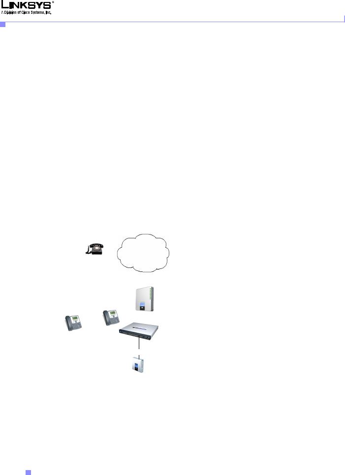
SPA400 SIP-PSTN Gateway
When a local user on the SPA9000 network initiates a call to a PSTN subscriber, the SPA400 acts as the SIP-PSTN gateway, which converts the SIP and RTP media packets into the appropriate signal for transmission to the PSTN switch. For example, if UserA calls UserD, the SIP request is routed by the SIP proxy in the SPA9000 to the SPA400. The SPA400 then converts the SIP and RTP packets it receives from UserA and the signals it receives from the PSTN switch.
Figure 1-4 The SPA400 as a SIP-PSTN Gateway
|
|
|
|
|
|
PSTN |
||||
|
UserD |
|||||||||
|
|
|
|
|
|
|||||
|
|
|
|
|
|
|
|
|
|
1 to 4 DID lines |
|
|
|
|
|
|
|
|
|
|
|
|
|
|
|
|
|
|
|
|
|
SPA400 |
|
|
|
|
|
|
|
|
|
|
|
|
|
UserB |
|
|
|
|
SIP-PSTN |
|||
|
|
|
|
|
|
Gateway |
||||
UserA |
|
|
|
|
Switch |
|||||
|
|
|
|
|||||||
|
|
|
|
|
|
|
|
|
|
|
|
|
|
|
|
|
|
|
|
|
|
|
|
|
|
|
|
|
|
|
|
|
Internet (WAN) Interface
SPA9000
SIP Proxy
Linksys SPA9000 Administrator Guide
1-8 |
Version 3.0 |
|
|

Chapter 1 Using the Linksys Voice System
Technology Background
Network Address Translation (NAT)
This section describes issues that arise when using the LVS on a network behind a network address translation (NA) device. It includes the following topics:
•NAT Overview, page 1-9
•NAT Types, page 1-10
•Simple Traversal of UDP Through NAT, page 1-10
•SIP-NAT Interoperation, page 1-11
NAT Overview
Network Address Translation (NAT) allows multiple devices to share the same public, routable, IP address for establishing connections over the Internet. NAT is typically performed by a router that forwards packets between the Internet and the internal, private network.
A typical application of a NAT is to allow all the devices in a subscriber home network to access the Internet through a router with a single public IP address assigned by an ISP. The IP header of the packets sent from the private network to the public network is substituted by NAT with the public IP address and a port assigned by the router. The receiver of the packets on the public network sees the packets as coming from the external address instead of the private address of the device.
The association between a private address and port and a public address and port is called a NAT mapping. This mapping is maintained for a short period of time, that varies from a few seconds to several minutes. The expiration time is extended whenever the mapping is used to send a packet from the source device.
Figure 1-5 NAT Support with Session Border Controller Provided by ITSP
Private IP address |
External IP address |
192.168.1.1 |
assigned by ISP |
192.168.1.101 192.168.1.102
NAT Device |
|
ISP |
Internet |
DHCP |
|
server |
|
SPA9000
SIP Proxy |
|
ITSP |
|
|
|
|
|
||
Session Border |
||||
192.168.1.100 |
||||
Controller |
||||
|
||||
The ITSP may support NAT mapping using a Session Border Controller. This is the preferred option because it eliminates the need for managing NAT on the SPA9000. If this is not available, you will need to discuss with the ITSP how to use the NAT Support Parameters provided by the SPA9000, such as <Outbound Proxy> and <STUN Server Enable>.
Linksys SPA9000 Administrator Guide
|
Version 3.0 |
1-9 |
|
|
|

Chapter 1 Using the Linksys Voice System
Technology Background
NAT Types
The different ways that NAT is implemented is sometimes divided into the following categories:
•Full cone NAT—Also known as one-to-one NAT. All requests from the same internal IP address and port are mapped to the same external IP address and port. An external host can send a packet to the internal host, by sending a packet to the mapped external address
•Restricted cone NAT—All requests from the same internal IP address and port are mapped to the same external IP address and port. Unlike a full cone NAT, an external host can send a packet to the internal host only if the internal host had previously sent a packet to it.
•Port restricted cone NAT/symmetric NAT—Port restricted cone NAT or symmetric NAT is like a restricted cone NAT, but the restriction includes port numbers. Specifically, an external host can send a packet to a particular port on the internal host only if the internal host had previously sent a packet from that port to the external host.
With symmetric NAT all requests from the same internal IP address and port to a specific destination IP address and port are mapped to a unique external source IP address and port. If the same internal host sends a packet with the same source address and port to a different destination, a different mapping is used. Only an external host that receives a packet can send a UDP packet back to the internal host.
Simple Traversal of UDP Through NAT
Simple Traversal of UDP through NATs (STUN) is a protocol defined by RFC 3489, that allows a client behind a NAT device to find out its public address, the type of NAT it is behind, and the port associated on the Internet connection with a particular local port. This information is used to set up UDP communication between two hosts that are both behind NAT routers. Open source STUN software can be obtained at the following website:
http://www.voip-info.org/wiki-Open+Source+VOIP+Software
STUN does not work with a symmetric NAT router. To determine the type of NAT your router uses, complete the following steps:
Step 1 Enable debugging on the SPA9000:
1.Make sure you do not have firewall running on your PC that could block the syslog port (by default this is 514).
2.On the administration web server, System tab, set <Debug Server> to the IP address and port number of your syslog server.
Note that this address and port number has to be reachable from the SPA.
3.Set <Debug level> to 3 but you do not need to change the value of the <syslog server> parameter.
4.To capture SIP signaling messages, under the Line tab, set <SIP Debug Option> to Full. The output is named syslog.514.log.
Step 2 To determine the type of NAT your router is using set <STUN Test Enable> to yes.
Step 3 View the syslog messages to determine if your network uses symmetric NAT or not.
Linksys SPA9000 Administrator Guide
1-10 |
Version 3.0 |
|
|

Chapter 1 Using the Linksys Voice System
SPA9000 Architecture
SIP-NAT Interoperation
In the case of SIP, the addresses where messages/data should be sent to a SPA9000 system are embedded in the SIP messages sent by the device. If the SPA9000 system is sitting behind a NAT device, the private IP address assigned to it is not usable for communications with the SIP entities outside the private network.
Note If the ITSP offers an outbound NAT-Aware proxy, this discovers the public IP address from the remote endpoint and eliminates the need to modify the SIP message from the UAC.
The SPA9000 system must substitute the private IP address information with the proper external IP address/port in the mapping chosen by the underlying NAT to communicate with a particular public peer address/port. For this, the SPA9000 system needs to perform the following tasks:
•Discover the NAT mappings used to communicate with the peer.
This can be done with the help of an external device, such as a STUN server. A STUN server responds to a special NAT-Mapping-Discovery request by sending back a message to the source IP address/port of the request, where the message contains the source IP address/port of the original request. The SPA9000 system can send this request when it first attempts to communicate with a SIP entity over the Internet. It then stores the mapping discovery results returned by the server.
•Communicate the NAT mapping information to the external SIP entities.
If the entity is a SIP Registrar, the information should be carried in the Contact header that overwrites the private address/port information. If the entity is another SIP UA when establishing a call, the information should be carried in the Contact header as well as in the SDP embedded in SIP message bodies. The VIA header in outbound SIP requests might also need to be substituted with the public address if the UAS relies on it to route back responses.
•Extend the discovered NAT mappings by sending keep-alive packets.
Because the mapping is alive only for a short period, the SPA9000 system continues to send periodic keep-alive packets through the mapping to extend its validity as necessary.
SPA9000 Architecture
This section describes the basic architecture, function, and configuration options for the SPA9000. It includes the following topics:
•Architectural Components, page 1-12
•Multicast Addressing and Group Paging, page 1-13
•Configuration Options, page 1-14
Linksys SPA9000 Administrator Guide
|
Version 3.0 |
1-11 |
|
|
|
Chapter 1 Using the Linksys Voice System
SPA9000 Architecture
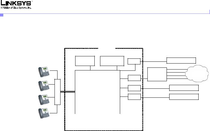
Architectural Components
Figure 1-6 SPA9000 Architecture
SPA9000
Switch
Application |
Administration |
Line 1 |
(408)111-1000 to 7 |
ITSP SIP Proxy |
|
server |
web server |
|
|
||
|
|
|
|
||
|
|
|
SPA 400 |
(408)111-1111 |
|
|
|
|
(408)111-1112 |
PSTN |
|
|
|
|
SIP-PSTN |
(408)111-1113 |
|
SIP Proxy |
Line 2 |
gateway |
(408)111-1114 |
|
|
|
|
|
|
||
SIP Registrar |
Line 3 |
(949)111-2000 to 7 |
ITSP SIP Proxy |
||
|
|
||||
Media (RTP) Proxy |
Line 4 |
(888)111-3000 to 7 |
ITSP SIP Proxy |
||
|
|
|
|
||
|
|
|
|
|
|
|
|
|
|
|
|
|
|
|
|
|
|
|
|
|
|
|
|
|
|
|
|
|
|
|
|
|
|
|
|
|
|
|
|
|
|
|
|
|
|
|
|
|
Call |
|
FXS1 |
|
|
FXS2 |
|
aa |
|
imusic |
|
park |
|||||||
|
|
|
|
|
|
|
|
|
|
|
|
|
|
|
|
|
As shown in Figure 1-6, the SPA 9000 provides four logical line interfaces, referred to as Line 1, 2, 3, and 4. Each line can be configured with the same or a different ITSP. Each SPA400 also occupies one line interface. The SPA9000 has five internal clients that register implicitly with the internal SIP proxy:
•FXS1 (fxs1)
•FXS2 (fxs2)
•Call Park (callpark)
•Auto-Attendant (aa)
•Internal Music Server (imusic)
FXS1 and FXS2 correspond to the two physical FXS ports. The FXS ports can only register with the local SIP proxy. The Call Park is used to maintain calls that are parked, and AA is a scriptable auto-attendant application.
Table 1-1 Architectural Components
|
|
|
|
Architectural Component |
Function |
|
|
|
|
|
|
|
|
|
|
|
|
|
|
SIP proxy and Registrar server |
Accepts registration from client stations and |
||
|
|
|
|
|
proxies SIP messages. |
||
|
|
|
|
|
|
|
|
|
|
|
|
Media proxy server |
Proxies RTP packets between client stations and |
||
|
|
|
|
|
proxies SIP messages. |
||
|
|
|
|
|
|
|
|
|
|
|
|
Configuration server |
Serves configuration files to client stations and |
||
|
|
|
|
|
auto configures un-provisioned client stations. |
||
|
|
|
|
|
|
|
|
|
|
|
|
Application server |
Supports advanced features such as call |
||
|
|
|
|
|
park/pickup, directory, directed call pickup and |
||
|
|
|
|
|
group paging, hunt groups, and shared line |
||
|
|
|
|
|
appearances. |
||
|
|
|
|
|
|
|
|
|
|
|
Linksys SPA9000 Administrator Guide |
|
|
|
|
|
|
|
|
|
|
||
|
1-12 |
|
|
|
Version 3.0 |
|
|
|
|
|
|
|
|||

Chapter 1 Using the Linksys Voice System
|
|
SPA9000 Architecture |
|
|
Table 1-1 Architectural Components |
|
|
|
|
|
|
|
Architectural Component |
Function |
|
|
|
|
|
|
Internal music source |
Streams audio files to client stations (both on-net |
|
|
|
and off-net). |
|
|
|
The FXS1 and FXS2 can optionally be connected |
|
|
|
to an external music source to act as a streaming |
|
|
|
audio server (SAS). When working in this mode, |
|
|
|
each FXS port can handle up to 10 concurrent |
|
|
|
calls. |
|
|
|
|
|
|
Administration web server |
Allows configuration and monitoring of the |
|
|
|
SPA9000. |
|
|
|
|
|
|
ATA with 2 FXS ports |
Each FXS port can be connected to analog |
|
|
|
phones, fax machine, or an external music |
|
|
|
source. Each port can support up to two calls |
|
|
|
simultaneously. The FXS ports can only register |
|
|
|
to the internal proxy server. |
|
|
|
|
|
|
Call park |
The call park is used to maintain calls that are |
|
|
|
parked and can handle up to 10 calls |
|
|
|
simultaneously |
|
|
|
|
|
|
Auto-Attendant |
AA is a scriptable auto-attendant application that |
|
|
|
can handle up to 10 calls simultaneously |
|
|
|
|
|
Multicast Addressing and Group Paging
The <Multicast Address> parameter on the PBX Parameters page defines the multicast address used by the SPA9000 and the SPA900 Series phones to communicate with each other. The default value is 224.168.168.168:6061. This address can also be set using the IVR option 181 and reviewed using option 180.
The <Group Page Address> parameter is used by the SPA9000 for group paging of all active client stations. The default value is 224.168.168.168:34567.
The SPA9000 can send the following messages to the phone group:
•Graceful Reboot
•Immediate Reboot
•Graceful Restart
•Immediate Restart
•Group Page Start
•Group Page End
•Get Ringing Calls
Client stations send multicast messages to the SPA9000 when they are looking for the configuration server.
Linksys SPA9000 Administrator Guide
|
Version 3.0 |
1-13 |
|
|
|

Chapter 1 Using the Linksys Voice System
SPA9000 Architecture
Configuration Options
This section describes the different methods for configuring the SPA9000. It includes the following topics:
•Interactive Voice Response, page 1-14
•Setup Wizard
•Administration Web Server
•Local Client Configuration and Registration, page 1-15
•Remote Provisioning of the SPA9000, page 1-15
Interactive Voice Response
The Interactive Voice Response (IVR), which is strictly for administration purposes, lets you use an analog phone to perform basic configuration and troubleshooting operations. To access the IVR, connect an analog phone to an FXS port and press **** to access the IVR menu.
For detailed information about using the IVR, refer to the “Using the Interactive Voice Response Interface” section on page 2-9. A convenient quick-reference for the IVR is available at the following website:
http://www.linksys.com/
Setup Wizard
The Setup Wizard is a convenient way to perform initial configuration for the SPA9000. It provides step-by-step guidance for configuring the basic operation of voice services, voicemail, and most of the main features provided by the SPA9000.
The Setup Wizard overwrites any existing configuration information that has been entered through the administration web server, so it should not be used for ongoing administration and configuration unless it provides adequate functionality for you to use it exclusively. You can, however, use the Setup Wizard for initial configuration and then use the administration web server for ongoing configuration and maintenance.
You can download the latest Setup Wizard from the following website: http://www.linksys.com/
To start the Wizard, just double-click on the executable file. For information about getting started with the Setup Wizard, refer to the “Using the Wizard for Initial Configuration” section on page 2-14
Administration Web Server
The administration web server provides a series of web pages that let you enter detailed configuration information for the many features and options provided by the SPA9000. It also lets you monitor the status of the attached client stations.
The administration server provides a basic and an advanced view from which the various configuration parameters can be accessed. The Provisioning tab is only visible from the advanced Administrator account view of the web interface.
To access the administration web server, direct a browser to the Internet (WAN) interface of the SPA9000. To determine this address, use IVR Option 110#.
Linksys SPA9000 Administrator Guide
1-14 |
Version 3.0 |
|
|

Chapter 1 Using the Linksys Voice System
SPA9000 Architecture
For detailed information about using the administration web server, refer to the “Using the Administration Web Server” section on page 2-23. For a description of each parameter provided by the administration web server, refer to Chapter 6, “SPA9000 Field Reference”
Local Client Configuration and Registration
SPA9000 provides a TFTP server to assign configuration information to the locally attached client stations. When the SPA9000 receives a request for /cfg/init_$MA.xml, it automatically assigns the next available user id (extension number) to the client station. The initial user ID is configured using the PBX Phone Parameters:<Next Auto User ID> parameter and is automatically incremented each time a new number is assigned. Before assigning a new user ID, the SPA9000 also checks if there is any registered client station using that ID and increases the ID until an unused value is found.
Remote Provisioning of the SPA9000
The SPA9000 provides for secure provisioning and remote upgrade. Provisioning is achieved through configuration profiles transferred to the device via TFTP, HTTP, or HTTPS. User intervention is not required to initiate or complete a profile update or firmware upgrade.
The SPA9000 can be configured to automatically resync its internal configuration state to a remote profile periodically and during power up. The automatic resync is controlled by configuring the profile URL for the device.
The SPA9000 accepts profiles in XML format, or alternatively in a proprietary binary format, which can be generated by a profile compiler tool available to qualified VoIP vendors and partners from Linksys. The SPA9000 supports up to 256-bit symmetric key encryption of profiles. For the initial transfer of the profile encryption key (initial provisioning stage), the SPA9000 can receive a profile from an encrypted channel (HTTPS with client authentication), or it can resync to a binary profile generated by the Linksys-supplied profile compiler. In the latter case, the profile compiler can encrypt the profile specifically for the target SPA9000, without requiring an explicit key exchange.
Remote firmware upgrade is achieved via TFTP or HTTP (firmware upgrades using HTTPS are not supported). Remote upgrades are controlled by configuring the desired firmware image URL into the SPA9000 via a remote profile resync.
For further information about remote provisioning refer to the LVS SPA Provisioning Guide.
Linksys SPA9000 Administrator Guide
|
Version 3.0 |
1-15 |
|
|
|

Chapter 1 Using the Linksys Voice System
Where to Go From Here
Where to Go From Here
The following table summarizes the steps required to implement and configure the SPA9000 system and indicates where to look for the information required.
Task |
Refer to |
|
|
Establishing connectivity among system |
Chapter 2, “Getting Started.” |
components |
|
|
|
Configuring voice services and SPA400 or |
Chapter 3, “Configuring Voice Service and |
ITSP-hosted voicemail |
Voicemail.” |
|
|
Configuring and understanding SPA9000 features |
Chapter 4, “Configuring SPA9000 Features.” |
|
|
Configuring or writing XML scripts for the |
Chapter 5, “Configuring the LVS |
Auto-Attendant |
Auto-Attendant.” |
|
|
Identify the function or setting required for a |
Chapter 6, “SPA9000 Field Reference” |
specific parameter on the administration web |
|
server pages |
|
|
|
For additional information about specific functionality or features of the SPA9000, refer to the following documents:
•LVS CTI Integration Guide
•LVS Integration with ITSP Hosted Voicemail Guide
•Auto-Attendant Quick Guide
•Interactive Voice Response (IVR) Quick Guide
•SPA Provisioning Guide
•SPA900 Series IP Phones Administrator Guide
Linksys SPA9000 Administrator Guide
1-16 |
Version 3.0 |
|
|
Loading...