


 Loading...
Belt Drive Garage Door Opener
Model 8550
Write down the following information for future reference:
Serial Number:
Date of Purchase:
FOR RESIDENTIAL USE ONLY
■Please read this manual and the enclosed safety materials carefully!
■Fasten the manual near the garage door after installation.
■The door WILL NOT CLOSE unless the Protector System® is connected and properly aligned.
■Periodic checks of the garage door opener are required to ensure safe operation.
■The model number label is located on the left side panel of your garage door opener.
■This garage door opener is ONLY compatible with MyQ™ and Security ®2.0 accessories.
■DO NOT enable the Timer-To-Close feature if you are installing the garage door opener on a one-piece door. The Timer -To-Close is to be used ONLY with sectional doors.
NOTE: If you are installing the garage door opener on a one-piece door, visit www.liftmaster.com for installation instructions.
.
www.liftmaster.com
The Chamberlain Group, Inc.
845 Larch Avenue
Elmhurst, Illinois 60126-1196
Contents |
|
BELT DRIVE GARAGE DOOR OPENER .. 1 |
|
PREPARATION............................. |
2 |
ASSEMBLY ................................. |
4 |
INSTALLATION ........................ |
6-13 |
INSTALL THE DOOR CONTROL..... |
14-16 |
INSTALL THE |
|
PROTECTOR SYSTEM® .............. |
17-20 |
POWER ................................ |
21-22 |
ADJUSTMENT......................... |
23-25 |
BATTERY BACKUP ................... |
26-27 |
OPERATION ............................... |
28 |
FEATURES................................. |
29 |
DOOR CONTROL ..................... |
30-31 |
REMOTE CONTROLS................. |
32-33 |
TO ERASE THE MEMORY ............... |
33 |
TO OPEN THE DOOR MANUALLY ...... |
34 |
MAINTENANCE ........................... |
34 |
TROUBLESHOOTING................. |
35-36 |
REPAIR PARTS ....................... |
37-38 |
ACCESSORIES ............................ |
39 |
WARRANTY ............................... |
40 |
Preparation
Safety Symbol and Signal
Word Review
This garage door opener has been designed and tested to offer safe service provided itis installed, operated,maintained and tested in strict accordance with the instructions and warnings contained in this manual.
When you see these Safety Symbols and Signal Words on the following pages,they will alertyou to the possibility ofserious injury ordeathif you do not comply with the warnings that accompany them.The hazard may come from something mechanical or from electric shock.Read the warnings carefully.
Mechanical
Electrical
When you see this Signal Word on the following pages,itwill alertyou to the possibility of damage to your garage door and/or the garage door opener if you do not comply with the cautionary statements thataccompany it. Read them carefully.
Check the Door
1.Disable locks and remove any ropes connected to the garage door.
2.Lift the door halfway up. Release the door.If balanced,it should stay in place,supported entirely by its springs.
3.Raise and lower the door to check for binding or sticking.If your door binds, sticks,or is out of balance,call a trained door systems technician.
4.Check the seal on the bottom ofthe door.Any gap between the floor and the bottom of the door mustnotexceed 1/4 inch (6 mm).Otherwise,the safety reversal system may not work properly.
5.The opener should be installed above the center ofthe door.If there is a torsion spring or center bearing plate in the way ofthe header bracket,itmay be installed within 4 feet (1.2 m) to the leftor rightof the door center.See installing the Header Bracketsection.
Torsion Spring |
Extension Spring |
To preventpossible SERIOUS INJURY or DEATH:
•ALWAYS call a trained door systems technician ifgarage door binds,sticks,or is outofbalance.An unbalanced garage door maynotreverse when required.
•NEVERtryto loosen,move or adjust garage door,door springs,cables,pulleys, bracketsor their hardware,ALL ofwhich are under EXTREME tension.
•Disable ALL locksand remove ALL ropes connected to garage door BEFORE installation and operating garage door opener to avoid entanglement.
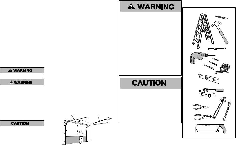
Tools Needed
5/32
3/16
5/16
1 |
2 |
To preventdamage to garage door and opener:
•ALWAYS disable locksBEFORE installing and operating the opener.
•ONLY operate garage door opener at 120 V,60 Hzto avoid malfunction and damage.
1/2
5/8 |
1/4 |
7/16 |
9/16 |
7/16 
2

Overview/Carton Inventory
NOTE: Accessories will vary depending on the garage door opener model purchased. Depending on your specific model, other accessories may be included with your garage door opener. The instructions for these accessories will be attached to the accessory and are not included in this manual. The images throughout this manuals are for reference and your product may look different.
GARAGE DOOR OPENER ASSEMBLY
A. Header bracket
B. Pulley and bracket
C. Door bracket
D. Curved door arm
E. Straight door arm
A 
 B
B
C |
F |
|
G |
D |
E |
|
F. Trolley
G. Emergency release rope and handle H. Rail
I. Garage door opener
K
H
J. Sprocket cover and screws K. Belt
L. Door control
M. White and red/white wire
The Protector System®
N. Safety reversing sensors
with white and white/black wire attached: Sending Sensor (1) Receiving Sensor (1) and Safety Sensor Brackets (2)
O. Safety labels and literature
L
M
J
 N
N
O
I
MyQ™ AND SECURITY ®2.0
ACCESSORIES
880LM |
|
Smart Control |
|
Panel® |
829LM |
|
|
|
Garage Door |
895MAX |
Monitor |
Remote Control |
|
Hardware
Assembly
H1 Hex Screw #8x3/8" (3) [packed with the sprocket cover]
Installation
H2 Hex Bolt 5/16"-18 x 7/8" (4) H3 Lag Screw 5/16"-9 x 1-5/8" (2)
H4 Lag Screw 5/16"-18 x 1-5/8" (2) H5 Clevis Pin 5/16" x 2-3/4" (1)
H6 Clevis Pin 5/16" x 1-1/4" (1)
H7 Clevis Pin 5/16" x 1" (1)
H8 Nut 5/16"-18 (4)
H9 Lock Washer 5/16"-16 (4)
H10 Self-Threading Screw 1/4"-14 x 5/8" (2) H11 Ring Fastener (3)
H12 Carriage Bolt 1/4"-20 x 1/2" (2)
H13 Wing Nut 1/4"-20 (2)
Door Control Hardware
H14 Screw 6AB x 1-1/4" (2)
H15 Screw 6-32 x 1" (2)
H16 Drywall Anchors (2)
H17 Insulated Staples (10)
3
Assembly
1 Attach the rail to the garage door opener
To avoid possible SERIOUS INJURY to finger from moving garage door opener:
•ALWAYS keep hand clear of sprocketwhile operating opener.
•Securely attach sprocketcover BEFORE operating.
To avoid SERIOUS damage to garage door opener,use ONLY those bolts/fasteners mounted in the top of the opener.
.
HARDWARE
Mounted in the garage door opener
H1 (3)
Hex Screw #8x3/8"
(Packed with the sprocket cover)
NOTE: ONLY use the boltsremoved fromthe |
|
garage door opener.Place the garage door |
|
opener on the packing material to prevent |
H1 |
scratching. |
|
1.1 Remove the two bolts from the top ofthe garage door opener.
1.2 Align the rail and the styrofoam over the sprocket.Cut the tape from the rail, belt, and styrofoam.
1.3 Fasten the rail with the previously removed bolts.
1.4 Position the belt around the garage door opener sprocket.
1.5 Attach the sprocketcover over the garage door opener sprocketand attach with hex screws (H1).
4

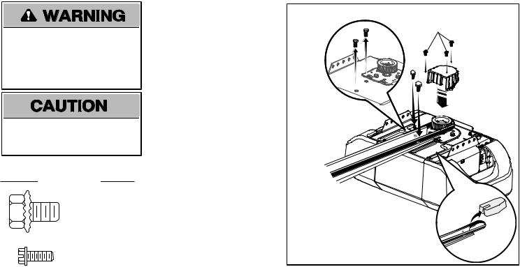
2 Tighten the Belt
2.1 |
By hand,thread the spring trolley nut on the threaded shaftuntil itis finger tightagainst |
2.2 Inserta flathead screwdriver tip into one of the nutring slots and brace it firmly againstthe trolley. |
|
the trolley.Do notuse any tools. |
|
|
(To motor unit) |
|
|
Spring Trolley Nut |
Nut ring |
|
slot |
|
|
|
2.3Tighten the spring trolley nutwith an adjustable wrench or a 7/16” open end wrench abouta quarter turn until the spring releases and snaps the nut ring againstthe trolley.This sets the spring to optimum belt tension.
Nut Ring |
Nut Ring |
|
BEFORE |
|
|
|
|
|
|
AFTER RELEASE |
|||||
|
|
|
|
||||||||||
|
|
1" |
|
|
|
|
|
|
|
|
1-1/4" |
|
|
|
|
|
|
|
|||||||||
|
(2.5 cm) |
|
|
|
|
|
|
|
(3.18 cm) |
||||
5

Installation
IMPORTANT INSTALLATION INSTRUCTIONS

 WARNING
To reduce the risk of SEVERE INJURY or DEATH:
1.READ AND FOLLOW ALL INSTALLATION WARNINGS AND INSTRUCTIONS.
2.Install garage door opener only on properly balanced and lubricated garage door.An improperly balanced door may notreverse when required and could resultin SEVERE INJURY or DEATH.
3.ALL repairs to cables,spring assemblies and other hardware MUST be made by a trained door systems technician BEFORE installing opener.
4.Disable ALL locks and remove ALL ropes connected to garage door BEFORE installing opener to avoid entanglement.
5.Install garage door opener 7 feet(2.13 m) or more above floor.
6.Mountthe emergency release within reach,but atleast6 feet(1.83 m) above the floor and avoiding contactwith vehicles to avoid accidental release.
7.NEVER connectgarage door opener to power source until instructed to do so
8.NEVER wear watches,ringsor loose clothing while installing or servicing opener.Theycould be caughtin garage door or opener mechanisms.
9.Install wall-mounted garage door control:
•within sightofthe garage door.
•outofreach ofchildren atminimumheightof5 feet(1.5 m).
•awayfromALL moving partsofthe door.
10.Place entrapmentwarning label on wall nextto garage door control
11.Place manual release/safetyreverse testlabel in plain viewon inside ofgarage door.
12.Upon completion ofinstallation,testsafetyreversal system.Door MUSTreverse on.contactwith a 1-1/2" (3.8 cm) high object(or a 2x4 laid fl at) on the floor.
13.To avoid SERIOUS PERSONAL INJURY or DEATHfromelectrocution,disconnectALL electricand batterypower BEFORE performing anyservice or maintenance.
14.DO NOTenable the Timer-to-Close functionalityifoperating either one-piece or swinging garage doors.To be enabled ONLY when operating a sectional door.
NOTE: Ifyou are installing the garage door opener on a one-piece door,visitwww.liftmaster.comfor installation instructions.
6
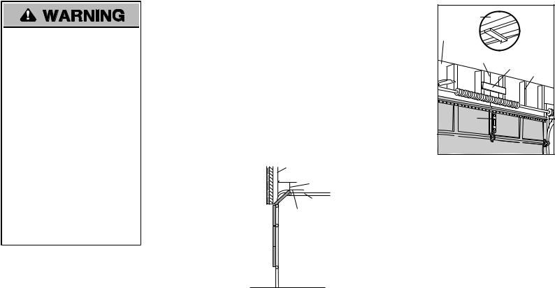
1 Determine the header bracket location
To preventpossible SERIOUS INJURY or DEATH:
•Header bracketMUST be RIGIDLY fastened to structural supporton header wall or ceiling,otherwise garage door might NOT reverse when required.DO NOT install header bracketover drywall.
•Concrete anchors MUST be used if mounting header bracketor 2x4 into masonry.
•NEVER try to loosen,move or adjust garage door,springs,cables,pulleys, brackets,or their hardware,ALL of which are under EXTREME tension.
•ALWAYS call a trained door systems technician if garage door binds,sticks,or is out ofbalance.An unbalanced garage door mightNOT reverse when required.
•DO NOT enable the Timer-to-Close functionality if operating either one-piece or swinging garage doors.To be enabled ONLY when operating a sectional door.
NOTE: Ifyou are installing the garage door opener on a one-piece door,visitwww.liftmaster.comfor installation instructions.
1.1Close the door and mark the inside vertical centerline of the garage door.
1.2Extend the line onto the header wall above the door.
Youcanfastenthe headerbracket within4 feet (1.22 m) of the left orright of the door centeronly if a torsionspringorcenterbearingplate is inthe way; oryoucanattachit to the ceilingwhenclearance is minimal.(It may be mountedonthe wallupside downif necessary,togainapproximately 1/2" (1 cm).
If you need to install the header bracketon a 2x4 (on wall or ceiling),use lag screws (not provided) to securely fasten the 2x4 to structural supports.
1.3Open your door to the highestpointof travel as shown.Draw an intersecting horizontal line on the header wall 2" (5 cm) above the high point.This heightwill provide travel clearance for the top edge of the door.
NOTE: Ifthe total number ofinchesexceedsthe heightavailable in your garage,use the maximum heightpossible,or refer to page 8 ceiling installation.
Header Wall
2" (5 cm)
Track
Highest Point
of Travel
 Door
Door
Unfinished Ceiling |
OPTIONAL |
|
|
||
|
CEILING |
|
|
MOUNT FOR |
|
Header Wall |
HEADER |
|
BRACKET |
||
|
||
2x4 |
|
|
Vertical Centerline |
|
|
of Garage Door |
|
|
2x4 |
Structural |
|
|
Supports |
|
Level |
|
|
(Optional) |
|
SECTIONAL DOOR WITH CURVED TRACK
7
Installation
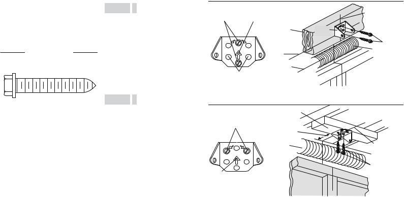
2 Install the Header Bracket
You can attach the header bracketeither to the wall above the garage door,or to the ceiling. Follow the instructions which will work bestfor your particular requirements.Donot installthe headerbracket overdrywall.If installinginto masonry,use concrete anchors (not provided).
HARDWARE
H3 (2)
LAG SCREW 5/16"-9X1-5/8"
OPTION A WALL INSTALLATION
2.1A Center the bracketon the vertical centerline with the bottom edge ofthe bracketon the horizontal line as shown (with the arrow pointing toward the ceiling).
2.2A Mark the vertical setof bracketholes (do not use the holes designated for ceiling mount).Drill 3/16" pilotholes and fasten the bracketsecurely to a structural supportwith the hardware provided (H3).
OPTION B CEILING INSTALLATION
2.1B Extend the vertical centerline onto the ceiling as shown.
2.2B Center the bracketon the vertical mark, no more than 6" (15 cm) from the wall. Make sure the arrow is pointing away from the wall.The bracketcan be mounted flush againstthe ceiling when clearance is minimal.
2.3B Mark the side holes.Drill 3/16" pilotholes and fasten bracketsecurely to a structural supportwith the hardware provided (H3).
The nail hole is for positioning only. You must use lag screws
Wall Mount to mount the header bracket.
|
2x4 Structural |
|
Support |
CEILING MOUNT ONLY |
|
UP |
Horizontal |
|
|
|
Line |
|
Highest Point of |
|
Garage Door |
Optional |
Travel |
Mounting
Holes
Header
Bracket
(Header Wall) |
Vertical |
|
|
|
Centerline of |
|
Garage Door |
Header
Bracket
H3
Door Spring
(Garage Door)
(Finished Ceiling)
Ceiling Mounting Holes |
|
|
|
6" (15 cm) |
|
|
Maximum |
|
CEILING MOUNT ONLY |
Door Spring |
Vertical |
|
|
|
UP |
|
Centerline of |
|
Garage Door |
|
|
|
|
|
|
H3 |
The nail hole is for positioning
only. You must use lag screws (Garage Door) (Header Wall) to mount the header bracket.
8
3 Attach the rail to the header bracket
3.1Align the rail with the header bracket. Insertthe clevis pin (H5) through the holes in the header bracketand rail. Secure with the ring fastener (H11).
NOTE: Use the packing material asa protective base for the garage door opener.
H11 |
H5 |
HARDWARE
|
|
|
|
|
|
|
|
|
|
|
|
|
|
|
|
|
|
|
|
|
|
|
|
|
|
|
H5 |
H11 |
|
|
|
Clevis Pin |
||
|
|
Ring Fastener |
||
|
|
5/16"x2-3/4" |
||
|
|
|
|
|
4 Position the garage door opener
To preventdamage to garage door,rest garage door opener rail on 2x4 placed on top section of door.
4.1Remove the packing material and liftthe garage door opener onto a ladder.
NOTE: A 2x4 isideal for setting the distance between the rail and the door.Ifthe ladder is nottall enough you will need help atthispoint.
4.2Fully open the door and place a 2x4 (laid flat) under the rail.
NOTE: Ifthe door hitsthe trolleywhen itisraised,pull the trolleyrelease armdown to disconnectthe inner and outer trolley.Slide the outer trolleytoward the garage door opener. The trolleycan remain disconnected until instructed.
CONNECTED DISCONNECTED
9
Installation
5 Hang the garage door opener
To avoid possible SERIOUS INJURY from a falling garage door opener,fasten itSECURELY to
structural supports ofthe garage.Concrete anchors MUST be used if installing ANY brackets into masonry.
|
|
|
|
|
|
|
|
|
|
|
|
|
|
|
|
|
|
|
|
|
|
|
|
|
|
|
HARDWARE |
|
|
|
|
|
|
|
|
|
|
|
|
|
|
|
|
|
|
|
|
|
|
|
|
|
|
|
|
H4 (2) |
|
|
|
|
|
|
|
|
|
H8 (2) |
|
H2 (2) |
|||||||||||||||||||||||||||||||||||||
|
|
|
|
|
|
|
|
|
|
|
H9 (2) |
|
||||||||||||||||||||||||||||||||||||||||
|
|
|
Lag Screw 5/16"- 18x1-5/8" |
|
|
|
|
|
|
|
|
|
||||||||||||||||||||||||||||||||||||||||
|
|
|
|
|
|
|
|
|
|
|
Lock Washer |
Nut 5/16"-18 |
|
Hex Bolt 5/16"- 18x7/8" |
||||||||||||||||||||||||||||||||||||||
|
|
|
|
|
|
|
|
|
|
|
|
|
|
|
|
|
|
|
|
|
|
|
|
|
|
|
||||||||||||||||||||||||||
|
|
|
|
|
|
|
|
|
|
|
|
|
|
|
|
|
|
|
|
|
|
|
|
|
|
5/16"-16 |
|
|
|
|
|
|
|
|
|
|
|
|
|
|
|
|
|
|
|
|
|
|
|
|
|
|
|
|
|
|
|
|
|
|
|
|
|
|
|
|
|
|
|
|
|
|
|
|
|
|
|
|
|
|
|
|
|
|
|
|
|
|
|
|
|
|
|
|
|
|
|
|
|
|
|
|
|
||
|
|
|
|
|
|
|
|
|
|
|
|
|
|
|
|
|
|
|
|
|
|
|
|
|
|
|
|
|
|
|
|
|
|
|
|
|
|
|
|
|
|
|
|
|
|
|
|
|
|
|
|
|
|
|
|
|
|
|
|
|
|
|
|
|
|
|
|
|
|
|
|
|
|
|
|
|
|
|
|
|
|
|
|
|
|
|
|
|
|
|
|
|
|
|
|
|
|
|
|
|
|
|
|
|
|
|
|
|
|
|
|
|
|
|
|
|
|
|
|
|
|
|
|
|
|
|
|
|
|
|
|
|
|
|
|
|
|
|
|
|
|
|
|
|
|
|
|
|
|
|
|
|
|
|
|
|
|
|
|
|
|
|
|
|
|
|
|
|
|
|
|
|
|
|
|
|
|
|
|
|
|
|
|
|
|
|
|
|
|
|
|
|
|
|
|
|
|
|
|
|
|
|
|
|
|
|
|
|
|
|
|
|
|
|
|
|
|
|
|
|
|
|
|
|
|
|
|
|
|
|
|
|
|
|
|
|
|
|
|
|
|
|
|
|
|
|
|
|
|
|
|
|
|
|
|
|
|
|
|
|
|
|
|
|
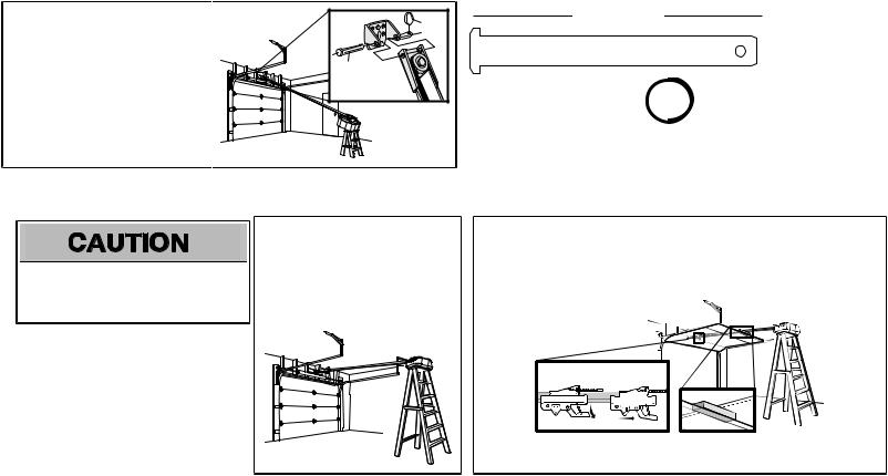
Hanging the garage door opener will vary depending on your garage.Below are three example installations.Your installation may be different.For ALL installations the garage door opener MUST be connected to structural supports.The instructions illustrate one ofthe examples below.
Finished Ceiling
5.1On finished ceilings,use the lag screws (H3) to attach a supportbracket(not provided) to the structural supports before installing the garage door opener.
(not provided)
H4
Finished |
|
Ceiling |
H4 |
5.2Make sure the garage door opener is aligned with the header bracket.Measure the distance from each side ofthe garage door opener to the supportbracket.
5.3Cutboth pieces of the hanging bracketto required lengths.
Unfinished Ceiling
5.4Attach the end ofeach hanging bracketto the supportbracketwith appropriate hardware (notprovided).
(not provided) 
5.5Attach the garage door opener to the hanging brackets with the bolts (H2),lock washers (H9) and nuts (H8).
H2
H9
H8
5.6Remove the 2x4 and manually close the door.If the door hits the rail, raise the header bracket.
10
6 Install the light bulbs
To preventpossible OVERHEATING ofthe end panel or lightsocket:
•Use ONLY A19 incandescentor compactfluorescentlightbulbs.
•DO NOT use incandescentbulbs larger than 100W.
•DO NOT use compactfluorescentlightbulbs larger than 26W (100W) equivalent.
•DO NOT use halogen bulbs.
•DO NOT use shortneck or specialty lightbulbs.
6.1Pull on the top center of the lightlens and rotate the lightlens down.
6.2Insertan A19 incandescentor compact fluorescentlightbulb (100 watt maximum), into the lightsocket.
6.3Rotate the lens up to close.
NOTE: The use ofshortneckor specialitylight bulbsmayoverheatthe end panel or lightsocket.
OR |
OR |
7 Attach the emergency release rope and handle
To preventpossible SERIOUS INJURY or DEATH from a falling garage door:
•Ifpossible,use emergency release handle to disengage trolley ONLY when garage door is CLOSED.Weak or broken springs or unbalanced door could resultin an open door falling rapidly and/or unexpectedly.
•NEVER use emergency release handle unless garage doorway is clear ofpersons and obstructions.
•NEVER use handle to pull door open or closed.Ifrope knotbecomes untied,you could fall.
7.1Insertone end of the emergency release rope through the handle.Make sure that “NOTICE” is rightside up. Tie a knotat least1 inch (2.5 cm) from the end ofthe emergency release rope.
7.2Insertthe other end ofthe emergency release rope through the hole in the trolley release arm.Make sure the handle is 6 feet(1.83 m) above the floor and secure with a knot.
NOTE: Ifitisnecessaryto cutthe emergencyrelease rope,seal the cutend with a match or lighter to preventunraveling.Ensure the emergencyrelease rope and handle are above the top ofall vehiclesto avoid entanglement.
Trolley |
Release Arm |
11
Installation
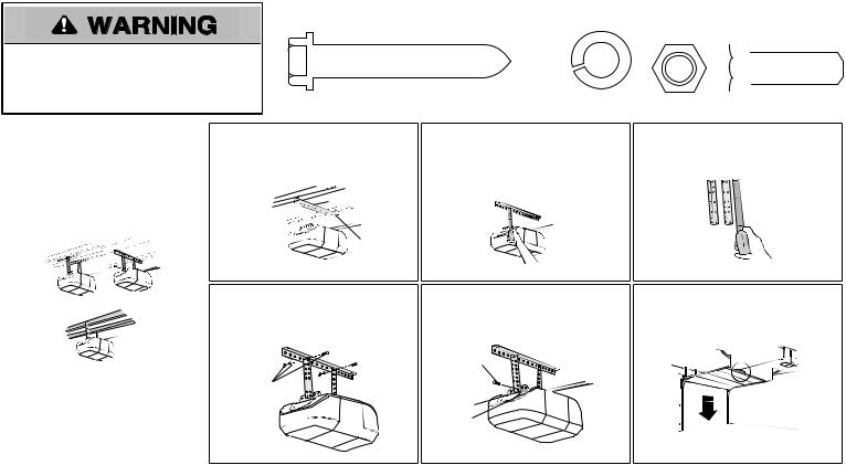
8 Install the door bracket
Fiberglass,aluminum or lightweightsteel garage doorsWILLREQUIRE reinforcementBEFORE installation of door bracket.Contactyour door manufacturer for reinforcementkit.
Ahorizontalandverticalreinforcement is neededforlightweight garage doors (fiberglass,aluminum,steel,doors withglass panel,etc.) (not provided). Ahorizontalreinforcement brace shouldbe longenoughtobe securedtotwoorthree verticalsupports.Averticalreinforcement brace shouldcoverthe height of the toppanel.
Figure 1 shows one piece of angle iron as the horizontal brace.For the vertical brace,2 pieces of angle iron are used to create a U-shaped support.The bestsolution is to check with your garage door manufacturer for an opener installation door reinforcementkit.
NOTE: Manydoor reinforcementkitsprovide for direct attachmentofthe clevispin and door arm.In thiscase you will notneed the door bracket;proceed to the nextstep.
HARDWARE
H10 (2)
Self-Threading Screw 1/4˝-14x5/8˝
8.1 Center the door bracketon the previously marked vertical centerline used for the header bracket installation.Note correctUP placement,as stamped inside the bracket.
8.2 Position the top edge of the bracket2"-4" (5-10 cm) below the top edge of the door,OR directly below any structural supportacross the top ofthe door.
8.3Mark,drill holes and install as follows,depending on your door’s construction:
Metalorlight weight doors usinga verticalangle ironbrace betweenthe doorpanelsupport and the doorbracket:
•Drill 3/16" fastening holes.Secure the door bracketusing the two self threading screws (H10). (Figure 2)
• Alternately,use two 5/16" bolts,lock washers and nuts (not provided).(Figure 3)
Metal,insulatedorlight weight factory reinforceddoors:
• Drill 3/16" fastening holes.Secure the door bracketusing the self-threading screws (H10). (Figure 4)
WoodDoors:
• Use top and bottom or side to side door bracketholes.Drill 5/16” holes through the door and secure bracketwith 5/16"x2" carriage bolts,lock washers and nuts (notprovided).(Figure 5)
NOTE: The 1/4"-14x5/8" self-threading screwsare notintended for use on wood doors.
FIGURE 2
Vertical
Reinforcement
Vertical
Centerline
of Garage Door

 UP
UP
Door
Bracket
H10 


FIGURE 4
Vertical
Centerline
of Garage
Door

 UP
UP
H10
FIGURE 1
FIGURE 3
Vertical Reinforcement
|
Vertical |
|
Centerline |
|
of Garage Door |
Bolt |
|
5/16"-18x2" |
|
(Not Provided) |
UP |
|
|
Door |
|
Bracket |
|
Lock Washer |
|
5/16" |
Nut |
|
5/16"-18 |
FIGURE 5
Bolt 5/16"x2" |
Inside Edge |
|
(Not Provided) |
||
of Door or |
||
|
||
|
Reinforcement Board |
|
|
UP |
|
Vertical |
|
|
Centerline |
|
|
of Garage |
|
|
Door |
|
12
Loading...