


CONTROLLER
GL BOARD
MODEL SL585
HEAVY DUTY SLIDE GATE OPERATOR
MODEL SL595
2 YEAR WARRANTY
HEAVY DUTY, HARSH ENVIRONMENT
SLIDE GATE OPERATOR
MODELS SL585 AND SL595 ARE FOR VEHICULAR PASSAGE GATES ONLY AND ARE NOT INTENDED FOR PEDESTRIAN PASSAGE GATE USE

T A B L E O F C O N T E N T S
OPERATOR SPECIFICATIONS
Carton Inventory . . . . . . . . . . . . . . . . . . . . . . . . . . . . . . . . . . . . .2 Operator Dimensions and Horsepower Chart . . . . . . . . . . . . . . .3 UL325 Model Classifications . . . . . . . . . . . . . . . . . . . . . . . . . . . .4
OPERATOR WARNINGS
Safety Installation Information . . . . . . . . . . . . . . . . . . . . . . . . . .5 Suggested Entrapment Protection Device Locations . . . . . . . . . .6 Safety Precautions for Open Roller Gates . . . . . . . . . . . . . . . . . .7 Warning Sign Placement . . . . . . . . . . . . . . . . . . . . . . . . . . . . . . .7
WIRING
Power Wiring Installation . . . . . . . . . . . . . . . . . . . . . . . . . . . . . .8
INSTALLATION
Pad Mounting (SL585 & SL595) . . . . . . . . . . . . . . . . . . . . . . . . .9 Post Mounting (SL585 & SL595) . . . . . . . . . . . . . . . . . . . . . . .10 Install Gate Bracket and Drive Chain . . . . . . . . . . . . . . . . . . . . .11 On/Off Switch Power Wiring . . . . . . . . . . . . . . . . . . . . . . . . . . .12 Manual Disconnect . . . . . . . . . . . . . . . . . . . . . . . . . . . . . . . . . .12
ADJUSTMENT
Limit Switch Adjustment . . . . . . . . . . . . . . . . . . . . . . . . . . . . . .13 RPM Sensor Adjustment (Hall Effect) . . . . . . . . . . . . . . . . . . . .13 Gate System Test Procedures . . . . . . . . . . . . . . . . . . . . . . . . . .13
Vent Plug . . . . . . . . . . . . . . . . . . . . . . . . . . . . . . . . . . . . . . . . . .14 UL325 Entrapment Protection . . . . . . . . . . . . . . . . . . . . . . .14-15 Control Board Illustration . . . . . . . . . . . . . . . . . . . . . . . . . . . . .15 Program Settings . . . . . . . . . . . . . . . . . . . . . . . . . . . . . . . . . . .16 Control Connection Diagrams . . . . . . . . . . . . . . . . . . . . . . . . . .17 Accessory Wiring . . . . . . . . . . . . . . . . . . . . . . . . . . . . . . . . .18-19 Sequenced Access Management System . . . . . . . . . . . . . . . . .20
OPERATION AND MAINTENANCE
Operator Maintenance . . . . . . . . . . . . . . . . . . . . . . . . . . . . . . . .21 Friction Clutch . . . . . . . . . . . . . . . . . . . . . . . . . . . . . . . . . . . . . .22 Solenoid Actuated Brake . . . . . . . . . . . . . . . . . . . . . . . . . . . . . .22 Control Board Programming and Features . . . . . . . . . . . . . .22-23 Troubleshooting . . . . . . . . . . . . . . . . . . . . . . . . . . . . . . . . . .24-25 Single Phase Schematic . . . . . . . . . . . . . . . . . . . . . . . . . . . . . .26 Single Phase Wiring Diagram . . . . . . . . . . . . . . . . . . . . . . . . . .27 Three Phase Schematic . . . . . . . . . . . . . . . . . . . . . . . . . . . . . . .28 Three Phase Wiring Diagram . . . . . . . . . . . . . . . . . . . . . . . . . . .29
REPAIR PARTS
Notes . . . . . . . . . . . . . . . . . . . . . . . . . . . . . . . . . . . . . . . . . . . . .30 Electrical Boxes . . . . . . . . . . . . . . . . . . . . . . . . . . . . . . . . . . . . .31 Repair Parts - Model SL585 . . . . . . . . . . . . . . . . . . . . . . . . . . .32 Illustrated Parts - Model SL585 . . . . . . . . . . . . . . . . . . . . . . . . .33 Repair Parts - Model SL595 . . . . . . . . . . . . . . . . . . . . . . . . . . .34 Illustrated Parts - Model SL595 . . . . . . . . . . . . . . . . . . . . . . . . .35 Safety Accessories for Secondary Entrapment Protection . . . .36 Notes . . . . . . . . . . . . . . . . . . . . . . . . . . . . . . . . . . . . . . . . . . . . .37 Warranty . . . . . . . . . . . . . . . . . . . . . . . . . . . . . . . . . . . . . . . . . .38 Service Information . . . . . . . . . . . . . . . . . . . . . . . . . . . . . . . . . .39
 WARNING
Mechanical
 WARNING
Electrical
CAUTION
When you see these Safety Symbols and Signal Words on the following pages, they will alert you to the possibility of SERIOUS INJURY or DEATH if you do not comply with the warnings that accompany them. The hazard may come from something mechanical or from electric shock. Read the warnings carefully.
When you see this Signal Word on the following pages, it will alert you to the possibility of damage to your gate and/or the gate operator if you do not comply with the cautionary statements that accompany it. Read them carefully.
CARTON INVENTORY
Before beginning your installation check that all components were provided and received undamaged. Refer to list below for factory provided parts.
HARDWARE KIT
SL585/SL595 (K77-34846)
Description |
Qty. |
Safety Gate Brochure |
1 |
Gate Bracket |
2 |
Take-Up Bolt |
2 |
Nickel Plated Chain #50 |
1 |
U-Bolt 2" 5/16-18 |
4 |
U-Bolt 3" 3/8-16 |
4 |
Square Head Set Screw 7/16-14 |
4 |
Hex Nut 1/2-13 |
4 |
Flange Nut 5/16"-18 |
8 |
Flange Nut 3/8"-16 |
8 |
Flat Washer 3/8" |
8 |
Flat Washer 1/2" |
4 |
Lock Washer 1/2" |
4 |
2
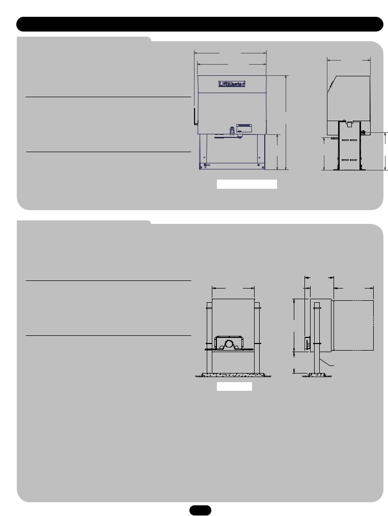
O P E R A T O R D I M E N S I O N S A N D H O R S E P O W E R C H A R T
28.9" |
|
(73.4 cm) |
17.2" |
|
|
27.5" |
(43.7 cm) |
(69.9 cm) |
|
37.7" (95.8 cm)
14.1" |
12.9" |
14.9" |
(35.8 cm) |
(32.8 cm) |
(37.9 cm) |
Opposite Gate Side
Gate Side
3
U L 3 2 5 M O D E L C L A S S I F I C A T I O N S
CLASS I – RESIDENTIAL VEHICULAR GATE OPERATOR
A vehicular gate operator (or system) intended for use in a home of one-to four single family dwellings, or a garage or parking area associated therewith.
CLASS II – COMMERCIAL/GENERAL ACCESS VEHICULAR GATE OPERATOR
A vehicular gate operator (or system) intended for use in a commercial location or building such as a multi-family housing unit (five or more single family units) hotel, garage, retail store or other building servicing the general public.
CLASS III – INDUSTRIAL/LIMITED ACCESS VEHICULAR GATE OPERATOR
A vehicular gate operator (or system) intended for use in a industrial location or building such as a factory or loading dock area or other location not intended to service the general public.
CLASS IV – RESTRICTED ACCESS VEHICULAR GATE OPERATOR
A vehicular gate operator (or system) intended for use in a guarded industrial location or building such as an airport security area or other restricted access locations not servicing the general public, in which unauthorized access is prevented via supervision by security personnel.
SAFETY ACCESSORY SELECTION
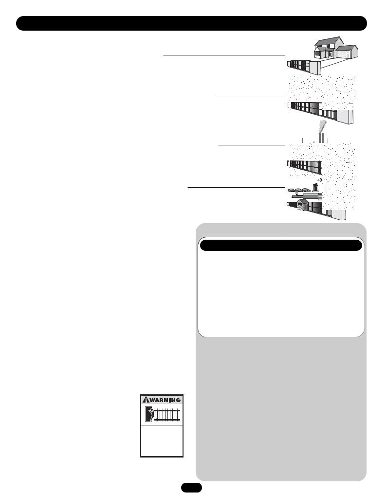
All UL325 compliant LiftMaster gate operators will accept external entrapment protection devices to protect people from motorized gate systems. UL325 requires that the type of entrapment protection correctly matches each gate application. Below are the six types of entrapment protection systems recognized by UL325 for use on this operator.
ENTRAPMENT PROTECTION TYPES
Type A: Inherent obstruction sensing system, self-contained within the operator. This system must sense and initiate the reverse of the gate within two seconds of contact with a solid object.
Type B1: Connections provided for a non-contact device, such as a photoelectric eye can be used as a secondary protection.
Type B2: Connections provided for a contact sensor. A contact device such as a gate edge can be used for secondary protection.
Type C: Inherent adjustable clutch or pressure relief valve.
Type D: Connections provided for a control requiring continuous pressure to operate the operator open and close.
Type E: Built-in audio alarm. Examples include sirens, horns or buzzers.
NOTE: UL requires that all installations must have warning signs placed in plain view on both sides of the gate to warn pedestrians of the dangers of motorized gate systems.
Moving Gate Can Cause
Injury or Death
KEEP CLEAR! Gate may move at any time without prior warning.
Do not let children operate the gate or play in the gate area.
This entrance is for vehicles only. Pedestrians must use separate entrance
UL325 ENTRAPMENT PROTECTION REQUIREMENTS
GATE OPERATOR ENTRAPMENT PROTECTION
|
UL325 |
Slide Gate Operator |
Swing & Gate Barrier |
|||
Installation |
|
|
(Arm) Operator |
|||
|
Class |
|
|
|
|
|
Primary |
Secondary |
Primary |
Secondary |
|||
|
|
|
Type |
Type |
Type |
Type |
|
|
|
|
|
|
|
|
Class |
A |
B1, B2 |
A or C |
A, B1, B2, |
|
|
I & II |
or D |
or C |
|||
|
|
|
||||
|
|
|
|
|
|
|
|
|
|
A, B1 or |
A, B1, B2, |
A, B1, B2 |
A, B1, B2, |
|
Class III |
|
||||
|
|
B2 |
D or E |
or C |
C, D or E |
|
|
|
|
||||
|
|
|
|
|
|
|
|
|
|
A, B1, B2 |
A, B1, B2, |
A, B1, B2, |
A, B1, B2, |
|
Class IV |
|
||||
|
|
or D |
D or E |
C or D |
C, D or E |
|
|
|
|
||||
|
|
|
|
|
|
|
4

S A F E T Y I N S T A L L A T I O N I N F O R M A T I O N
5

S U G G E S T E D E N T R A P M E N T P R O T E C T I O N D E V I C E L O C A T I O N S
Telephone |
Open |
Entry |
Edge |
System |
|
|
Close |
|
Edge |
STREET 4'
8'
Interrupt
(Safety) 4'
Loop Typical
Photo eye for |
4' |
Interrupt |
Typical |
||
close cycle |
|
(Safety) |
|
|
Loop |
COMPLEX
4'
Typical
OR
PARKING LOT
Photo eye for open cycle
Run twisted wire from Loop
to Operator*
Seal Loops*
1-1/2"
Loop wire* layer
1/4" or larger for Loop wire width depending on Loop wire size
6
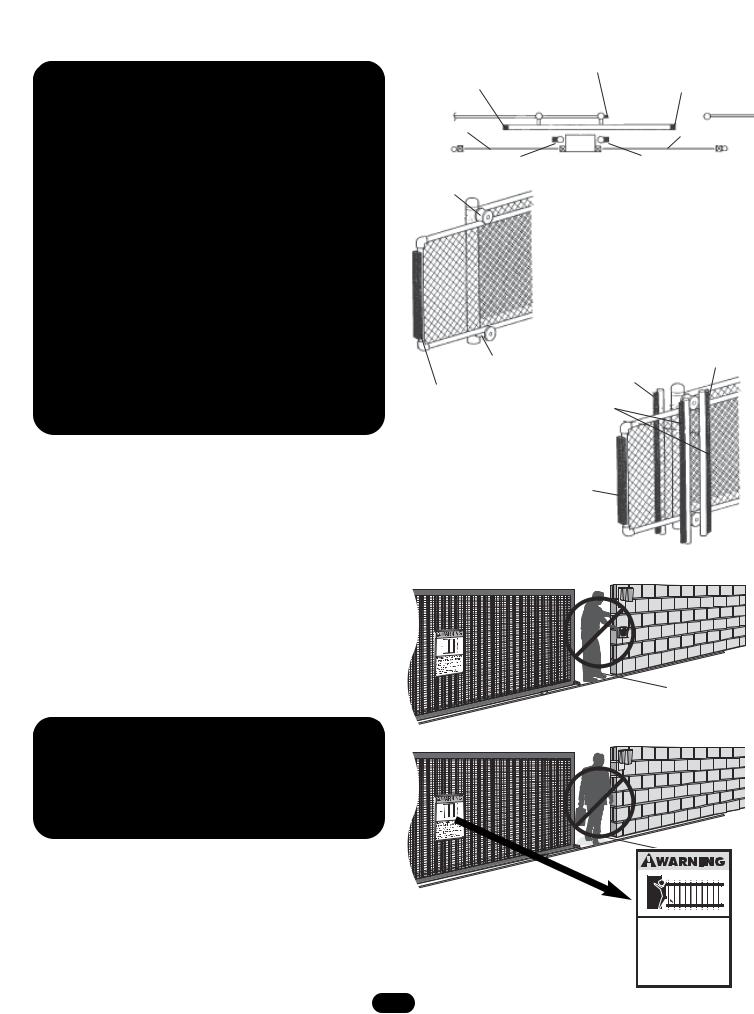
SAFETY PRECAUTIONS FOR OPEN ROLLER GATES
 WARNING
•Injuries occur when people get their hands or feet caught between the top or bottom of the gate and the gate roller. These potential pinch-points should be guarded against at all times. Enclosed style gate tracks are available for refitting of these rollers from many fence suppliers. Also, roller guards are available for installing over the rollers.
•UL325 requires that, when used, contact sensors shall be located at the leading edge, trailing edge, and be post mounted both inside and outside of a vehicular horizontal slide gate. Non-contact sensors such as photo eyes must protect during both open and close gate cycles.
•Injuries occur when people put their hands and arms through openings in the grill while the gate is operating. They cannot retract their arm and it gets caught between the moving gate grill and the stationary fence post or fence. This potential hazard can be averted by placing a 4' (1.2 m) screen mesh on the gate to prevent access through openings anywhere the gate may travel. See Safety Brochure for details. To prevent entrapment injuries, mount controls at least 6' (1.8 m) from the gate or any moving parts of the gate.
Gate Edge on |
Gate Edge on Fence |
|
||
Post for Open Direction |
Gate Edge On |
|||
Rear of Gate for |
||||
|
|
Leading Edge of Gate |
||
Open Direction |
|
|
||
|
|
For Close Direction |
||
|
|
|
||
Photo Beam |
|
|
Photo Beam for |
|
|
|
Close Direction |
||
for Open |
Unit |
|
||
|
|
|||
Direction |
|
Additional Post Mounted Gate |
||
Additional Post Mounted Gate |
||||
Edge for Close Direction |
Edge for Open Direction |
|||
Pinch-Point
Hazard
Always Test Gate Edges And
Photo Beams Anytime They Are
Adjusted Or Serviced
|
|
Gate Edge |
Pinch-Point |
|
For Close |
Gate Edge |
Direction |
|
Hazard |
|
|
For Open Direction |
|
|
|
|
Gate Edge
Vertical Post Placed On Both
Sides of the Exposed
Rollers Can Prevent Hands
From Reaching These
Pinch-points
Gate Edge for
Close Direction
 WARNING
NOT FOR USE AS PEDESTRIAN PASSAGE! This operator is intended for vehicular use only. To prevent INJURY to pedestrians, a separate pedestrian access should be supplied, visible from the gate. Locate the pedestrian access where there is not a chance of INJURY at any point during full movement of the gate.
Moving Gate Can Cause
Injury or Death
KEEP CLEAR! Gate may move at any time without prior warning.
Do not let children operate the gate or play in the gate area.
This entrance is for vehicles only. Pedestrians must use separate entrance
7

W I R I N G

 WARNING
WIRE GAUGE 6
SINGLE PHASE |
|
THREE PHASE |
|
|
115 Vac |
230 Vac |
230 Vac |
460 Vac |
575 Vac |
• |
1/2 HP Motor ------ |
425 ft. (129.5 m) |
1845 ft. (562.4 m) |
2557 ft. (779.4 m) |
12789 ft. (3898.1 m) |
15987 ft. (4872.8 m) |
• |
1 HP Motor---------- |
213 ft. (64.9 m) |
852 ft. (259.7 m) |
1278 ft. (389.5 m) |
5115 ft. (1559.1 m) |
7993 ft. (2436.3 m) |
• |
2 HP Motor---------- |
|
|
639 ft. (194.8 m) |
2557 ft. (779.4 m) |
4441 ft. (1353.6 m) |
WIRE GAUGE 8
• |
1/2 HP Motor ------ |
269 ft. (82 m) 1165 ft. (355.1 m) |
1614 ft. (492 m) |
8072 ft. (2460.4 m) |
10089 ft. (3075.1 m) |
• |
1 HP Motor---------- |
134 ft. (40.8 m) 537 ft. (163.7 m) |
807 ft. (246 m) |
3228 ft. (983.9 m) |
5044 ft. (1537.4 m) |
• |
2 HP Motor---------- |
|
403 ft. (122.8 m) |
1614 ft. (492 m) |
2525 ft. (769.6 m) |
WIRE GAUGE 10
• |
1/2 HP Motor ------ |
168 ft. (51.2 m) |
730 ft. (222.5 m) |
1012 ft. (308.5 m) |
5064 ft. (1543.5 m) |
6330 ft. (1929.4 m) |
• |
1 HP Motor---------- |
84 ft. (25.6 m) |
337 ft. (102.7 m) |
506 ft. (154.2 m) |
2025 ft. (617.2 m) |
3165 ft. (964.7 m) |
• |
2 HP Motor---------- |
|
|
252 ft. (76.8 m) |
1012 ft. (308.5 m) |
1582 ft. (482.2 m) |
WIRE GAUGE 12
• |
1/2 HP Motor ------ |
105 ft. (32 m) |
458 ft. (139.6 m) |
634 ft. (193.2 m) |
3171 ft. (966.5 m) |
3964 ft. (1208.2 m) |
• |
1 HP Motor---------- |
53 ft. (16.2 m) |
211 ft. (64.3 m) |
316 ft. (96.3 m) |
1269 ft. (386.8 m) |
1982 ft. (604.1 m) |
• |
2 HP Motor---------- |
|
|
157 ft. (47.9 m) |
634 ft. (193.2 m) |
990 ft. (301.8 m) |
|
|
|
|
|
|
|
|
|
|
|
|
|
|
8
I N S T A L L A T I O N
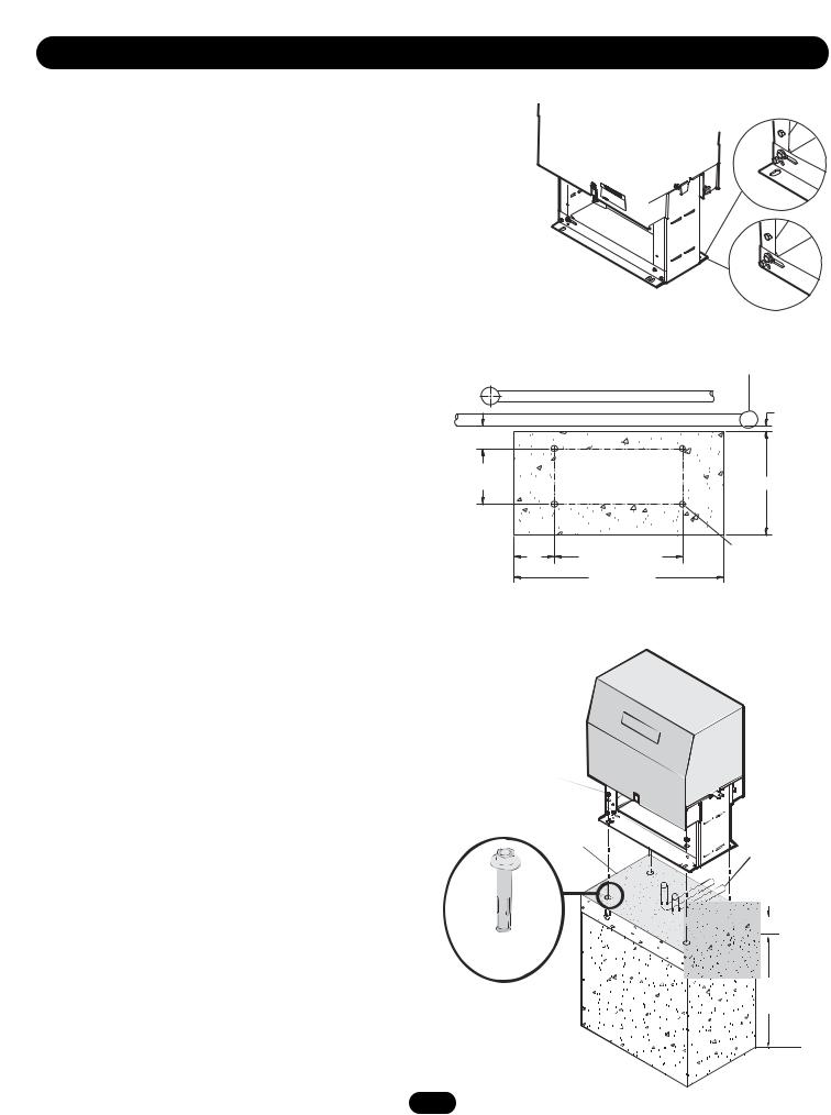
PAD MOUNTING (SL585 ONLY)
RETRO-FIT INSTALLATION
The operator is shipped from the factory with the lower mounting angles configured out (Figure 1). If you have pad constrictions, either angle can be unbolted and reversed to ‘angle in’.
NOTE: If you are replacing an SL580 and wish to use the same pad mounting hardware, the gate side mounting angle must be installed angle in.
NEW INSTALLATION
CONCRETE PAD PREPARATION:
1.Lay out concrete pad. (Figure 2).
2.Locate electrical conduit, as required, prior to pouring concrete.
3.Pour concrete pad.
4.Secure operator (Figure 3) to the concrete pad using four 1/2" (1.3 cm) concrete anchors (not provided).
Figure 1
Angle Out
Angle In
Figure 2
Rear of Gate or Back Frame
Fence Line
1" (2.5 cm)
4" (10.2 cm)
10-7/8" |
|
(27.6 cm) |
18" (45.7 cm) |
7" |
21-1/8" (53.7 cm) |
Concrete |
|
Anchor Holes |
|||
(17.8 cm) |
|
||
36" (91.4 cm) |
|
||
|
|
Figure 3
Using Suitable Hardware
To Secure Operator To
Concrete Anchors
Concrete
Drive and Idler
 SprocketToward
Gate Side
Power and Control
Wiring Should Be
Run In Separate Conduit


 2" to 4"
(5.1 to 10.2 cm) Above Grade
 Depth Required By
Local Codes or
Below Frost Line
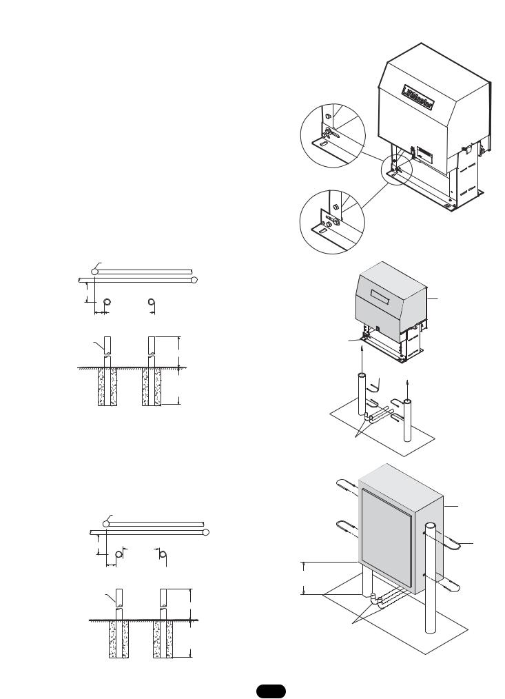
POST MOUNTING (SL585 AND SL595)
RETRO-FIT INSTALLATION
The operators come from the factory configured to mount to an inside the frame post mount dimension of 26" (outside to outside of posts). The frame comes slotted to accommodate posts 24 1/8" to 26", outside to outside (Figure 1).
NOTE: If you are replacing a SL580, the frame will require adjustment to 24 1/8".
NEW INSTALLATION (FIGURES 2 AND 3)
1.Locate and anchor two posts made of 3" (7.6 cm) outer diameter heavy walled pipe. Posts should be parallel and square to the gate.
2.Locate electrical conduit, as required, prior to pouring concrete.
3.Secure operator to posts using four 3" (7.6 cm) U-bolts and hardware provided.
Figure 2 |
End Post |
Fence Line |
|
||
|
|
|
8.5" (21.6 cm) |
|
Gate |
|
|
|
6" (15.2 cm) |
26" (66 cm) |
|
|
Outside To Outside |
|
3" (7.6 cm) Outside Diameter Heavy
Wall Fence Pipe
14" (35.6 cm) Min.
Ground Level
Depth As Required By
Local Codes or Below
Frost Line
Figure 1
26" (66 cm)
Post to Post Adjustment
24 1/8" (61 cm)
Figure 2
Drive and Idler
Sprocket Toward
Gate Side
Angle
Bracket
3" (7.6 cm) U-bolt (4 required)
SL585 ONLY
Figure 3
8.5" (21.6 cm)
6" (15.2 cm)
3" (7.6 cm) Outside Diameter Heavy Wall Fence Pipe
End Post |
Fence Line |
|
Gate
24" (61 cm)
Inside to inside
39" (99.1 cm) Min.
Ground Level
Depth As Required By
Local Codes or Below
Frost Line
SL595 ONLY
Power and Control
Wiring Should Be Run In
Separate Conduit
|
Drive and Idler |
Figure 3 |
Sprocket Toward |
Gate Side |
|
|
3" (7.6 cm) |
|
U-bolt |
|
(4 required) |
12" (30.5 cm) Minimum |
|
From Ground |
|
Power and Control
Wiring Should Be Run
In Separate Conduit
SL595 ONLY
10
INSTALL GATE BRACKET AND DRIVE CHAIN
CAUTION
To prevent damage to the operator or gate, DO NOT drive the limit (nuts) actuators on the shaft past their normal positions.
1.Mount gate brackets to the vertical front and rear posts of the gate (Figure 1).
2.Remove the operator cover or open access door.
3.Locate and engage the manual disconnect and lock it in place (refer to page 12).
4.Connect chain take-up bolt to the end of the chain and attach to the rear gate bracket (Figure 2).
5.Ensure that the drive and idler sprockets are in line with each other. Thread the chain through the plastic chain guide, around drive and idler sprockets, and then through the second plastic chain guide toward front gate bracket (Figure 3).
6.Adjust the chain to proper length and attach second take-up bolt to chain end. Secure the take-up bolt to the front gate bracket as shown.
Adjust nuts on chain take-up bolts to remove chain slack. A general rule of thumb is to leave a maximum of 1" (2.5 cm) of chain slack for every 10' (3.1 m) of chain length.
Do not overtighten chain.
NOTE ABOUT SOME TYPES OF CANTILEVER GATES:
With some cantilever gates over 20' (6.1 m) long, you may need to add a brace along the length of the gate to prevent the gate from bowing when chain is tightened. This may also be required on some styles of gates that are constructed out of aluminum. If positioned properly, this brace can also be used as a chain support.
Figure 3 |
Gate Bracket |
|
Idler Sprocket
Insert Chain Through Plastic Guides
Figure 1
“Outside”
Gate
“Inside”
2" (5.1 cm) U-bolts With Lock Washers
and Nuts
Gate Bracket |
Anti-Rotation |
Set Screw |
Figure 2
* *
*Gate brackets must be level and centered with bottom of idler sprocket
Drive Sprocket
Gate Post
Idler Sprocket
Safety Bracket
11
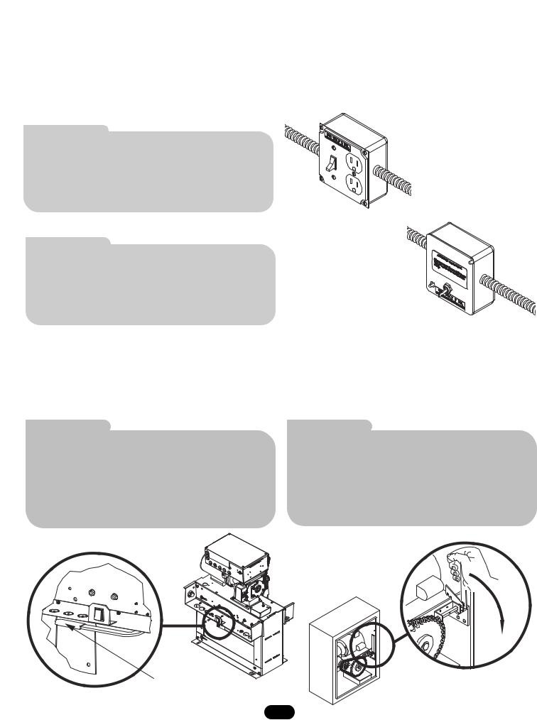
AVAILABLE CONDUIT ACCESS FOR THE ELECTRICAL BOX
The accessory tray is equipped with several 1-1/2" pass though holes as well as 3/4" and 1" knock outs for conduit connectors. The electrical box is equipped with 3/4" and 1" knock outs for conduit connectors.
ON/OFF SWITCH POWER WIRING
NOTES: Before running power wiring refer to wiring specifications on page 8 for correct wire gauges.
Secure all electrical power connections inside the disconnect switch electrical box. Refer to electrical wiring diagrams on pages 26-29.
SINGLE PHASE
All single phase 115V/208/230V operators will have the following:
•L1 WHITE
•L2 BLACK
•GROUND, GREEN
115V SINGLE PHASE POWER SWITCH ASSEMBLY
THREE PHASE
All three phase operators will have the following:
• L1 BLACK
•L2 BLACK
•L3 BLACK
•GROUND, GREEN
230V SINGLE PHASE &
THREE PHASE
POWER SWITCH ASSEMBLY
IMPORTANT NOTE: This operator is shipped from the factory as a right hand mounted unit, unit MUST be phased correctly. On three phase operators, power connections must be properly phased. If phased incorrectly, the gate operator will run reversed. To correct this situation, shut off power at main power source and at the operators electrical disconnect switch. Then reverse any two of the three power leads.
MANUAL DISCONNECT
MODEL SL585 |
|
MODEL SL595 |
|
DISENGAGEMENT: |
Rotate disconnect handle 90˚ to |
DISENGAGEMENT: |
Open the hinged door and pull the |
|
disengage. The gate may now be |
|
disconnect lever and lock it in place. |
|
moved manually. |
|
The gate my now be moved manually. |
RE-ENGAGEMENT: |
Rotate handle back to original |
RE-ENGAGEMENT: |
Release the lever and close the door. |
|
position. (Some operator output |
|
(Some operator output sprocket |
|
sprocket rotation may be required for |
|
rotation may be required for |
|
engagement). |
|
engagement). |
Pull the handle to release
12
 Loading...