


LGO50113L
Table of contents
 Loading...
MODELS LGO50113R, LGO50113L
LGO50113XR & LGO50113XL
LIGHT DUTY GRILL OPERATOR
OWNER’S MANUAL
Serial # Box
Installation Date
2 YEAR WARRANTY
NOT FOR RESIDENTIAL USE
LISTED DOOR OPERATOR
2
When you see these Safety Symbols and Signal Words on the
following pages, they will alert you to the possibility of serious
injury or death if you do not comply with the warnings that
accompany them. The hazard may come from something
mechanical or from electric shock. Read the warnings carefully.
When you see this Signal Word on the following pages, it will
alert you to the possibility of damage to your door and/or the
door operator if you do not comply with the cautionary
statements that accompany it. Read them carefully.
Mechanical
Electrical
• BEFORE attempting to install, operate or maintain the
operator, you must read and fully understand this manual
and follow all safety instructions.
• These instructions are intended to highlight certain safety
related issues. These instructions are not intended to be
comprehensive. Because each application is unique, it is the
responsibility of the purchaser, designer, installer and end
user to ensure that the total door system is safe for its
intended use.
TABLE OF CONTENTS
WARNING
WARNING
WARNING
WARNING
CAUTION
WARNING
WARNING
WARNING
WARNING
SPECIFICATIONS
Operator Specifications . . . . . . . . . . . . . . . . . . . . . . . . . . . . . . . .3
Operator Dimensions . . . . . . . . . . . . . . . . . . . . . . . . . . . . . . . . . .3
PREPARATION
Operator Preparation . . . . . . . . . . . . . . . . . . . . . . . . . . . . . . . . . .4
INSTALLATION
Operator Mounting . . . . . . . . . . . . . . . . . . . . . . . . . . . . . . . . . . . .5
Manual Operation . . . . . . . . . . . . . . . . . . . . . . . . . . . . . . . . . . . . .6
Door Operator System Illustration . . . . . . . . . . . . . . . . . . . . . . . .6
POWER & GROUND WIRING
Safety Warnings . . . . . . . . . . . . . . . . . . . . . . . . . . . . . . . . . . . . . .7
Three Prong Grounding Plug . . . . . . . . . . . . . . . . . . . . . . . . . . . .7
Permanent Wiring . . . . . . . . . . . . . . . . . . . . . . . . . . . . . . . . . . . .7
INSTALLATION OF DOOR CONTROLS
Three Button Station . . . . . . . . . . . . . . . . . . . . . . . . . . . . . . . . . . .8
Two Button/Two Position Key Switch . . . . . . . . . . . . . . . . . . . . . .8
PROGRAMMING OPERATING MODES
To Change Operating Modes . . . . . . . . . . . . . . . . . . . . . . . . . . . .9
ENTRAPMENT PROTECTION ACCESSORIES
Photo Eyes and Sensing Edges . . . . . . . . . . . . . . . . . . . . . . . . . .9
Connection Procedure . . . . . . . . . . . . . . . . . . . . . . . . . . . . . . . .10
ADJUSTMENTS
Limit Switch Adjustment . . . . . . . . . . . . . . . . . . . . . . . . . . . . . .11
Force Adjustment . . . . . . . . . . . . . . . . . . . . . . . . . . . . . . . . . . . .11
WIRING DIAGRAM
. . . . . . . . . . . . . . . . . . . . . . . . . . . . . . .12
TROUBLESHOOTING
Testing the Operator . . . . . . . . . . . . . . . . . . . . . . . . . . . . . . . . . .13
Troubleshooting Guide . . . . . . . . . . . . . . . . . . . . . . . . . . . . . . . .13
MAINTENANCE
Maintenance schedule . . . . . . . . . . . . . . . . . . . . . . . . . . . . . . . .14
CONTROL CONNECTIONS
Three Button Station . . . . . . . . . . . . . . . . . . . . . . . . . . . . . . . . .14
Two Button Station . . . . . . . . . . . . . . . . . . . . . . . . . . . . . . . . . . .14
Sensing Devices . . . . . . . . . . . . . . . . . . . . . . . . . . . . . . . . . . . . .14
ILLUSTRATED PARTS
Model LGO Parts . . . . . . . . . . . . . . . . . . . . . . . . . . . . . . . . . . . .15
Repair Parts Kits . . . . . . . . . . . . . . . . . . . . . . . . . . . . . . . . . . . .16
WARRANTY POLICY
. . . . . . . . . . . . . . . . . . . . . . . . . . . . . .17
OPERATOR NOTES
. . . . . . . . . . . . . . . . . . . . . . . . . . . . .18-19
REPAIR PARTS & SERVICE
. . . . . . . . . . . . . . . . . . . . . . .20
3
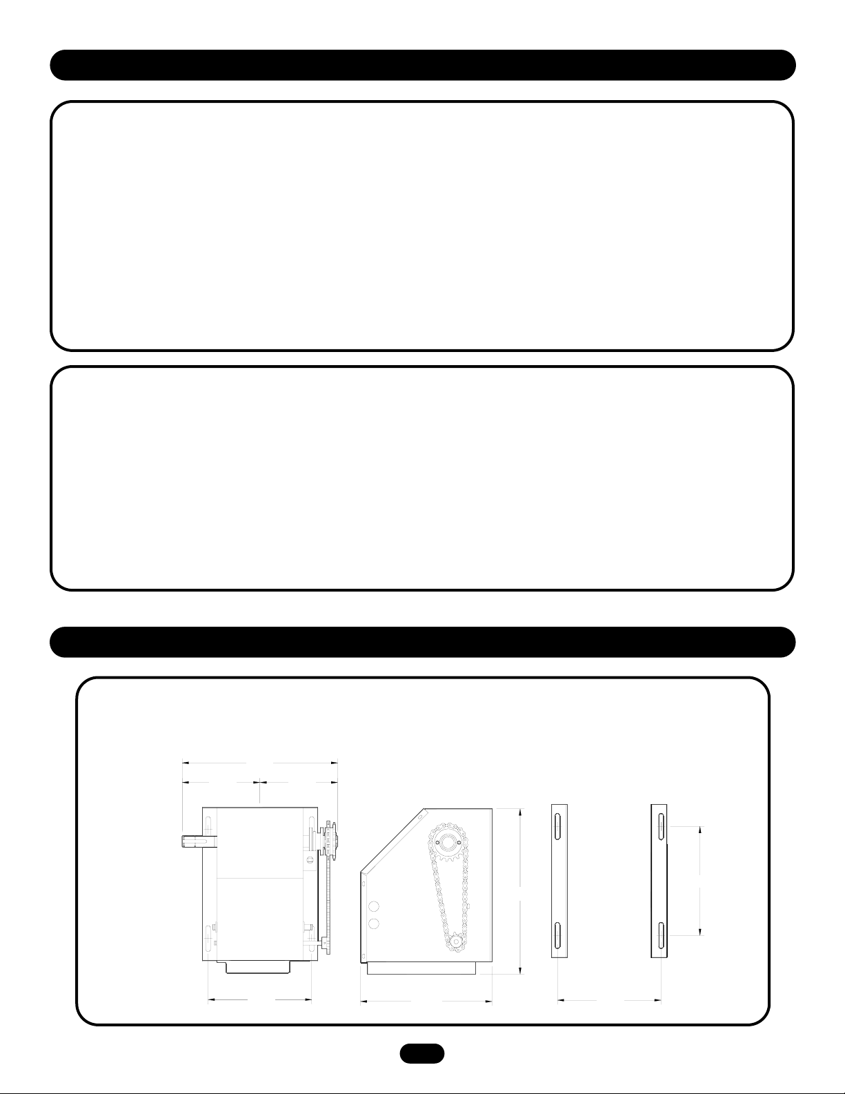
9.45"
11.42"
9.00"
14.31"
9.00"
6.75"
6.75"
13.5"
SAFETY
DISCONNECT: Floor level disconnect for emergency manual
door operation.
PHOTO EYES: Photo eyes to reverse door.
NOTE: LIFTMASTER PHOTO EYES P/N CPS-LN4 ARE
STRONGLY RECOMMENDED FOR ALL COMMERCIAL
OPERATOR INSTALLATIONS. REQUIRED WHEN ANY OTHER
CONTROL (AUTOMATIC OR MANUAL) IS USED.
MOTOR
TYPE: . . . . . . . . . . . . . . . . . . . . . . . . . . . . . . . Intermittent Duty
HORSEPOWER: . . . . . . . . . . . . . . . . . . . . . . . . 1/2 Horsepower
SPEED: . . . . . . . . . . . . . . . . . . . . . . . . . . . . . . . . . . . 1600 RPM
VOLTAGE: . . . . . . . . . . . . . . . . . . . . . . . . . 115V, 1 Phase, 60Hz
CURRENT: . . . . . . . . . . . . . . . . . . . . . . . . See Motor Nameplate
WEIGHTS AND DIMENSIONS
HANGING WEIGHT: 40-45 LBS.
ELECTRICAL
CONTROL STATION: NEMA 1 three button station.
OPEN/CLOSE/STOP or 2 button station OPEN/CLOSE.
RADIO: The internal radio receiver will not operate in D1
(constant pressure mode)
WIRING TYPES: B2 (Standard) Momentary contact to open,
close and stop, plus wiring for sensing device to reverse and
auxiliary devices to open and close with open override.
D1 (Optional) Constant pressure to open and close with wiring
for sensing devices to stop.
LIMIT ADJUST: Linear driven, fully adjustable screw type cams.
Adjustable to 24 feet.
MECHANICAL
DRIVE REDUCTION:
Primary: . . . . . . . . . . . . . . . . . . . . . . . . . . . .Worm Gear 16:1
Secondary: . . . . . . . . . . . . . . . . . . . . . . . .#48 Chain/Sprocket
Output: . . . . . . . . . . . . . . . . . . . . . . . . . . . . . . . . . .#41 Chain
OUTPUT SHAFT SPEED: . . . . . . . . . . . . . . . . . . . . . . .40 R.P.M.
DOOR SPEED: . . . . . . . . . . . . . . .9" per sec. depending on door
OPERATOR SPECIFICATIONS
OPERATOR DIMENSIONS
4
It is imperative that the wall or mounting surface provide adequate
support for the operator.
This surface must:
a. Be rigid to prevent play between operator and door shaft.
b. Provide a level base.
c. Permit the operator to be fastened securely and with the drive
shaft parallel to the door shaft.
The safety and wear of the operator will be adversely affected if
any of the above requirements are not met.
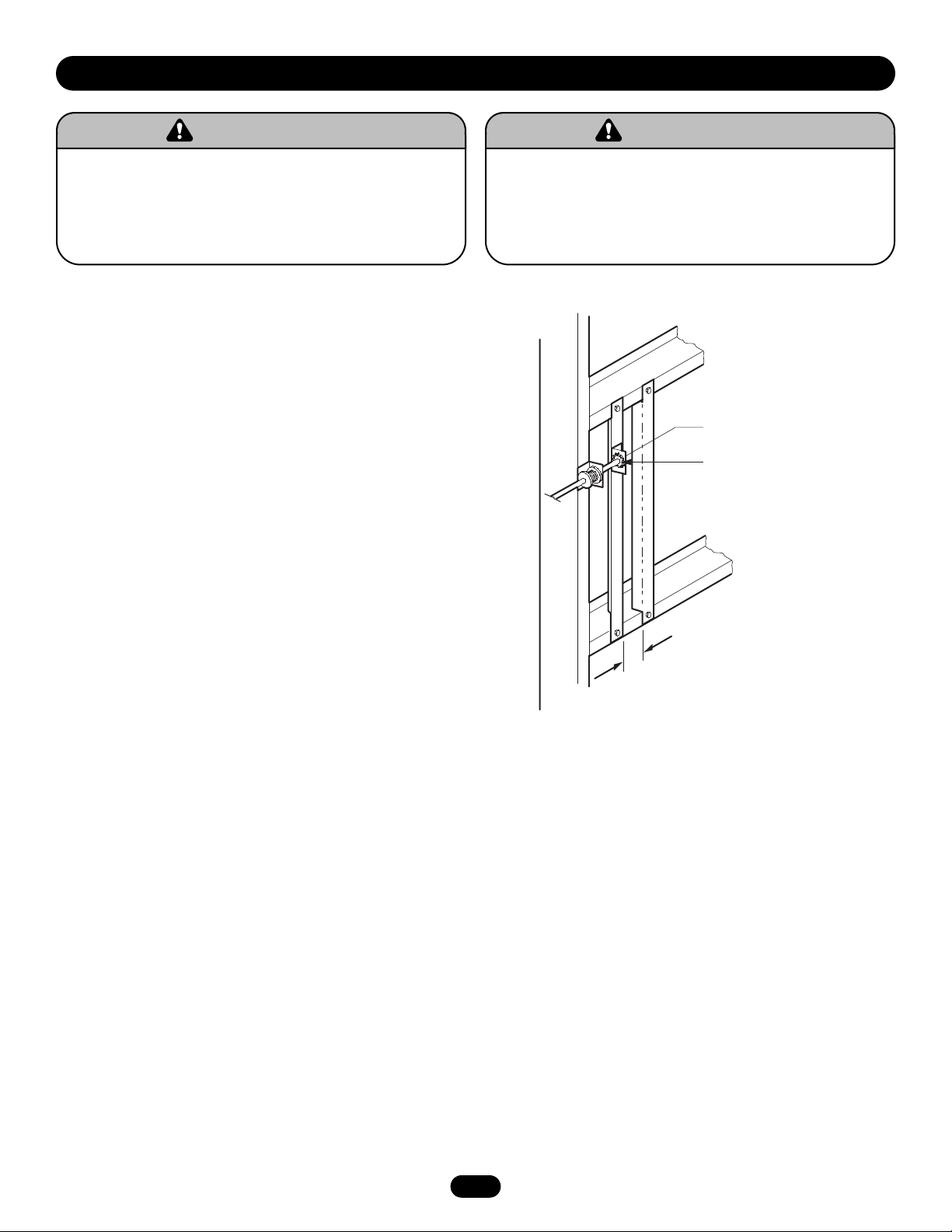
For metal buildings, fasten 2"x 2" x 3/16" (or larger) angle iron
frames to the building purlins. Retain 7" between frames.
7.00"
PREPARATION
To avoid damage to door and operator, make all door locks
inoperative. Secure lock(s) in “OPEN” position.
If the door lock needs to remain functional, install an interlock
switch.
DO NOT connect electric power until instructed to do so.
WARNING
WARNING
Keep door balanced. Sticking or binding doors MUST be
repaired. Doors, door springs, cables, pulleys, brackets and
their hardware may be under extreme tension and can cause
SERIOUS PERSONAL INJURY or DEATH. Call a professional
door serviceman to move or adjust door springs or hardware.
WARNING
WARNING
Shaft Support Bracket
with Bearing (Not Provided)
Door Sprocket
5-1/2"
Be sure door sprocket
is properly aligned with
drive sprocket before
securing to the shaft.
5
OPTIMUM DISTANCE
12-15"
Before your operator is installed, be sure the door has been properly aligned and is working smoothly. The operator may be wall
mounted or mounted on a bracket or shelf. If necessary, refer to the preparation on page 3. Refer to the instructions below that suit
your application.
INSTALLATION
OPERATOR MOUNTING
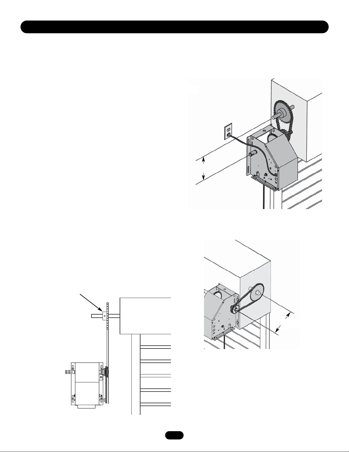
1. Wall Mount: The operator should generally be installed below
the door shaft, and as close to the door as possible (Figure 1).
Bracket or Shelf Mount: The operator may be mounted either
above or below the door shaft (Figure 2).
IMPORTANT: The shelf or bracket must provide adequate support,
prevent play between operator and door shaft, and permit
operator to be fastened securely and with the drive shaft parallel
to the door shaft.
NOTE: The optimum distance between the door shaft and operator
drive shaft is between 12" - 15".
2. Place door sprocket on the door shaft. Do not insert the key
at this time.
3. Place drive sprocket on the appropriate side of the operator.
4. Wrap drive chain around door sprocket and join roller chain
ends together with master link.
5. Raise operator to approximate mounting position and position
chain over operator sprocket.
6. Raise or lower operator until the chain is taut (not tight).
Make sure the operator output shaft is parallel to door shaft
and sprockets are aligned. When in position, secure the
operator to wall or mounting bracket.
7. Insert keys and align sprockets and secure (Figure 3).
Figure 1
Figure 2
Figure 3
OPTIMUM DISTANCE
12-15"
6
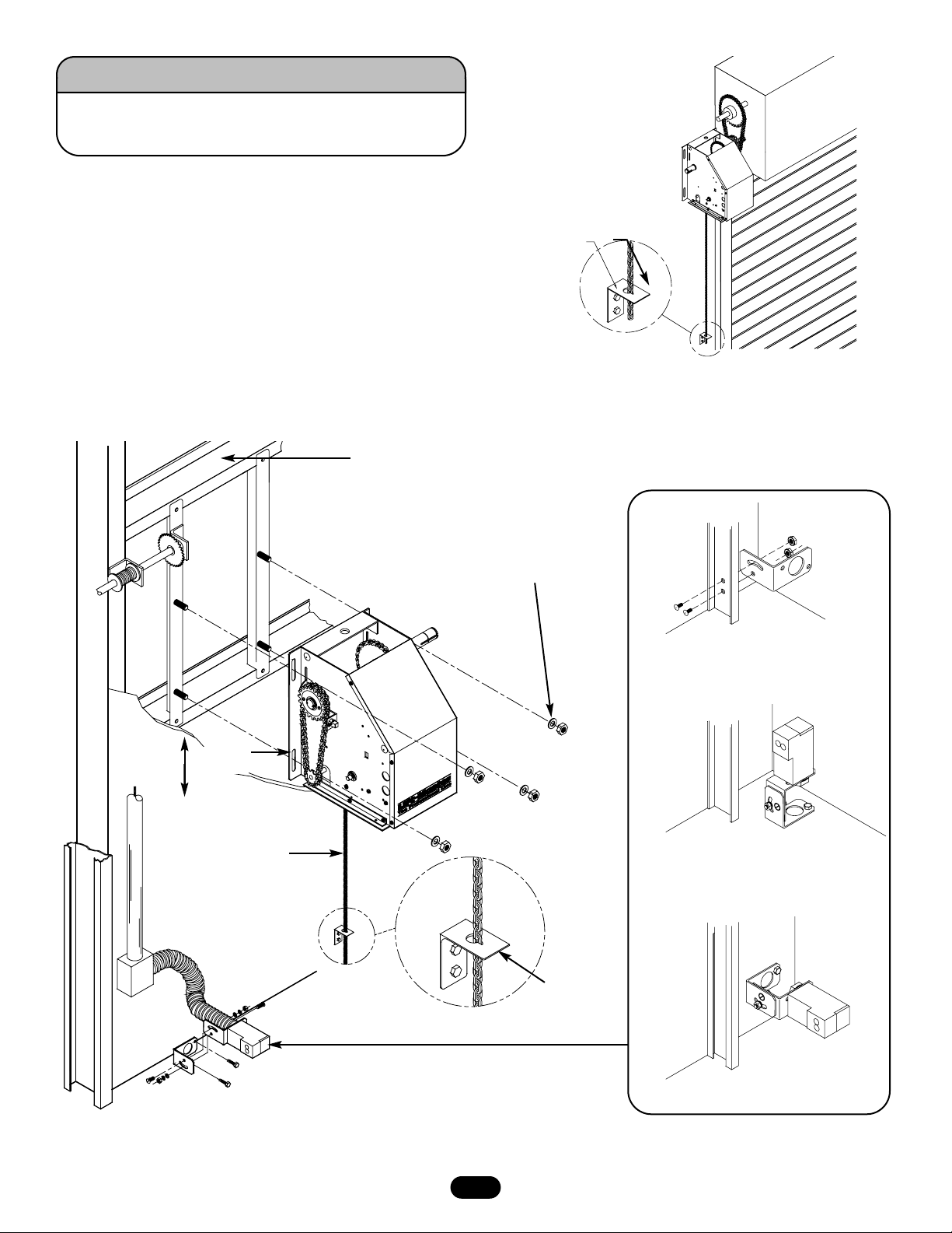
Keyhole Bracket
MANUAL OPERATION
This operator has a floor level disconnect chain to disconnect the
door from the door operator.
a. To disengage, pull the chain and secure in the disengaged
position by slipping the end through the keyhole bracket
mounted on the wall. If emergency egress device is used, pull
handle to disengage operator from the door.
b. The door may now be pushed up or pulled down manually.
Release the disconnect chain to operate the door again
electrically.
DOOR OPERATING SYSTEM ILLUSTRATION
ALTERNATE MOUNTING
FOR OPTIONAL PHOTO EYES
Rigid Mounting Surface
Keyhole
Bracket
Mounting Hardware
(Not Provided)
Track Mount
Floor Mount
Wall Mount
Pull Chain for
Manual Operation
Turn off power to the operator BEFORE manually operating
your door.
WARNING
CAUTION
WARNING
WARNING
To Adjust
Tension
Loading...