


 Loading...
LIGHT COMMERCIAL - RESIDENTIAL DC
VEHICULAR SWING GATE OPERATOR
INSTALLATION MANUAL
Model LA500UL
LA500PKGUL
Single Arm Package
LA500DC
Primary 24 VDC Actuator Arm for single swing gate applications
LA500DCS
Secondary 24 VDC Actuator Arm for dual swing gate applications
•THIS PRODUCT IS TO BE INSTALLED AND SERVICED BY A TRAINED GATE SYSTEMS TECHNICIAN ONLY.
•This model is for use on vehicular passage gates ONLY and not intended for use on pedestrian passage gates.
•This model is intended for use in Class I, II, III and IV vehicular swing gate applications.
•Visit LiftMaster.com to locate a professional installing dealer in your area.
•This gate operator is compatible with myQ® and Security+ 2.0® accessories.
OPERATOR REQUIRES A
LIFTMASTER EXTERNAL
MONITORED ENTRAPMENT
PROTECTION DEVICE BE
INSTALLED IN ALL
ENTRAPMENT ZONES
Access installation and technical support guides or register this product
1. Take a photo of the camera icon including the points ( ).
).
2. Send it in by texting the photo to 71403.

 LA500PKGULTECH

LiftMaster
300 Windsor Drive
Oak Brook, IL 60523

TABLE OF CONTENTS
SAFETY |
2 ACCESSORY WIRING |
31 |
Safety Symbol and Signal Word Review................................................... |
2 |
Usage Class............................................................................................... |
3 |
UL325 Entrapment Protection Requirements............................................ |
3 |
Safety Installation Information.................................................................. |
4 |
Gate Construction Information.................................................................. |
5 |
INTRODUCTION |
6 |
Carton Inventory........................................................................................ |
6 |
Operator Specifications............................................................................. |
7 |
Site Preparation......................................................................................... |
8 |
Check your gate......................................................................................... |
8 |
INSTALLATION |
9 |
Installation Tips......................................................................................... |
9 |
Step 1 Position the Brackets................................................................... |
10 |
Step 2 Attach the Brackets...................................................................... |
11 |
Step 3 Install the Control Box.................................................................. |
12 |
Step 4 Earth Ground Rod........................................................................ |
14 |
Step 5 Wire the Operator Arm to the Control Board................................ |
14 |
Step 6 Dual Gate Setup........................................................................... |
15 |
Step 7 Install Entrapment Protection....................................................... |
18 |
Wire Entrapment Protection Devices....................................................... |
19 |
Step 8 Power Wiring............................................................................... |
20 |
Step 9 Finish Installation......................................................................... |
22 |
ADJUSTMENT |
22 |
Limit and Force Adjustment.................................................................... |
22 |
Obstruction Test...................................................................................... |
24 |
PROGRAMMING |
25 |
Remote Controls (Not Provided)............................................................. |
25 |
LiftMaster Internet Gateway (Not Provided)............................................ |
26 |
Erase All Codes........................................................................................ |
26 |
Erase Limits............................................................................................. |
26 |
To Remove and Erase Monitored Entrapment Protection Devices.......... |
26 |
OPERATION |
27 |
Gate Operator Setup Examples................................................................ |
27 |
Control Board Overview........................................................................... |
28 |
Manual Release....................................................................................... |
29 |
Reset Button............................................................................................ |
29 |
Party Mode.............................................................................................. |
29 |
Operator Alarm........................................................................................ |
30 |
Remote Control....................................................................................... |
30 |
External Control Devices.......................................................................... |
31 |
Maglock................................................................................................... |
32 |
Miscellaneous Wiring.............................................................................. |
32 |
EXPANSION BOARD |
33 |
Expansion Board Overview...................................................................... |
33 |
Auxiliary Relays 1 and 2.......................................................................... |
34 |
Wiring Accessories to the Expansion Board............................................ |
35 |
MAINTENANCE |
36 |
Important Safety Instructions.................................................................. |
36 |
Maintenance Chart................................................................................... |
36 |
Batteries.................................................................................................. |
36 |
TROUBLESHOOTING |
37 |
Diagnostic Codes..................................................................................... |
37 |
Diagnostic Codes Table........................................................................... |
38 |
Control Board LEDs................................................................................. |
40 |
Troubleshooting Chart............................................................................. |
41 |
APPENDIX |
44 |
Installation Types.................................................................................... |
44 |
Step 1 Position the Brackets................................................................... |
44 |
Step 8 Solar Panels................................................................................. |
45 |
Limit Setup with a Remote Control......................................................... |
49 |
SAMS Wiring with the Relays Not Energized.......................................... |
50 |
REPAIR PARTS |
51 |
Standard Control Box.............................................................................. |
51 |
Large Metal Control Box.......................................................................... |
51 |
Gate Operator Arm.................................................................................. |
51 |
WIRING DIAGRAM |
52 |
Standard Control Box.............................................................................. |
52 |
Large Metal Control Box.......................................................................... |
53 |
ACCESSORIES |
54 |
WARRANTY |
56 |
SAFETY
Safety Symbol and Signal Word Review
When you see these Safety Symbols and Signal Words on the following pages, they will alert you to the possibility of Serious Injury or Death if you do not comply with the warnings that accompany them. The hazard may come from something mechanical or from electric shock. Read the warnings carefully.
When you see this Signal Word on the following pages, it will alert you to the possibility of damage to your gate and/or the gate operator if you do not comply with the cautionary statements that accompany it. Read them carefully.
IMPORTANT NOTE:
•BEFORE attempting to install, operate or maintain the operator, you must read and fully understand this manual and follow all safety instructions.
•DO NOT attempt repair or service of your gate operator unless you are an Authorized Service Technician.
MECHANICAL
ELECTRICAL
WARNING: This product can expose you to chemicals including lead, which are known to the State of California to cause cancer or birth defects or other reproductive harm. For more information go to www.P65Warnings.ca.gov.
2
SAFETY
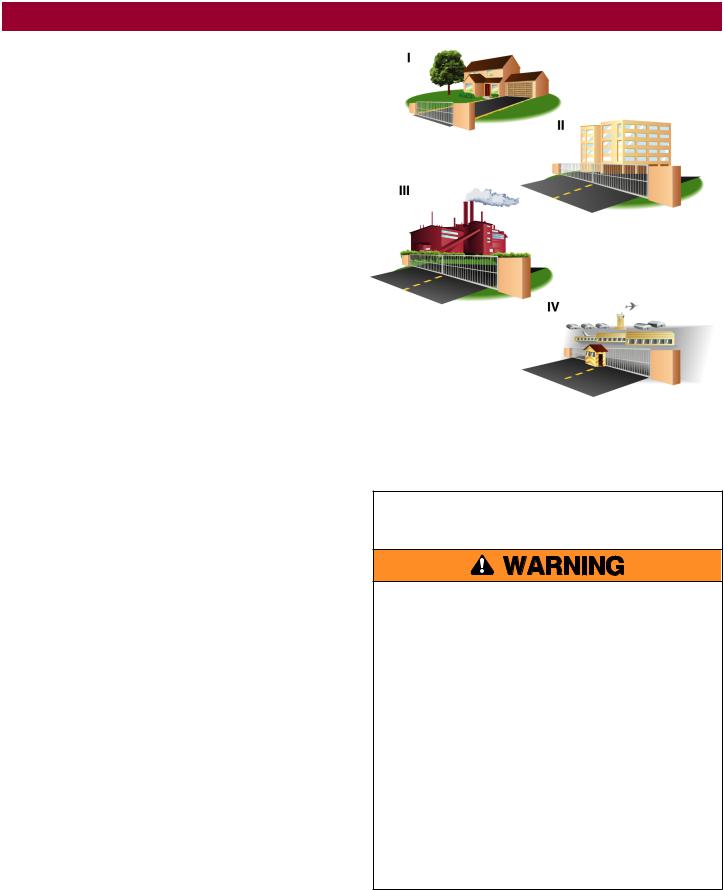
Usage Class
Class I - Residential Vehicular Gate Operator
A vehicular gate operator (or system) intended for use in garages or parking areas associated with a residence of one-to four single families.
Class II - Commercial/General Access Vehicular
Gate
A vehicular gate operator (or system) intended for use in a commercial location or building such as a multi-family housing unit (five or more single family units), hotel, garages, retail store, or other buildings accessible by or servicing the general public.
Class III - Industrial/Limited Access Vehicular
Gate
A vehicular gate operator (or system) intended for use in an industrial location or building such as a factory or loading dock area or other locations not accessible by or intended to service the general public.
Class IV - Restricted Access Vehicular Gate
Operator
A vehicular gate operator (or system) intended for use in a guarded industrial location or building such as an airport security area or other restricted access locations not servicing the general public, in which unauthorized access is prevented via supervision by security personnel.
UL325 Entrapment Protection Requirements
•A minimum of two independent* monitored entrapment protection devices are required to be installed at each entrapment zone
•Every installation is unique. It is the responsibility of the installer to install external monitored entrapment protection devices in each entrapment zone
•This vehicular swing gate operator will operate only after installation of a minimum of two independent* monitored entrapment protection devices in either the open or close direction. If no entrapment zone exists in the other direction of gate travel, then the inherent (built into the operator) is all that is required in that direction.
•Entrapment protection device types include inherent (built into the operator), monitored external photoelectric sensors or monitored external edge sensors
•This operator is provided with an inherent entrapment protection device built into the operator that serves as one of the two independent devices
*Independent - the same type of device shall NOT be used for both entrapment protection devices.
IMPORTANT SAFETY
INSTRUCTIONS
To reduce the risk of INJURY or DEATH:
•READ AND FOLLOW ALL INSTRUCTIONS.
•NEVER let children operate or play with gate controls. Keep the remote control away from children.
•ALWAYS keep people and objects away from the gate. NO ONE SHOULD CROSS THE PATH OF THE MOVING GATE.
•Test the gate operator monthly. The gate MUST reverse on contact with an object or reverse when an object activates the noncontact sensors. After adjusting the force or the limit of travel, retest the gate operator. Failure to adjust and retest the gate operator properly can increase the risk of INJURY or DEATH.
•Use the emergency release ONLY when the gate is not moving.
•KEEP GATES PROPERLY MAINTAINED. Read the owner’s manual. Have a qualified service person make repairs to gate hardware.
•The entrance is for vehicles ONLY. Pedestrians MUST use separate entrance.
•SAVE THESE
INSTRUCTIONS.
3

SAFETY
Safety Installation Information
1.Vehicular gate systems provide convenience and security. Gate systems are comprised of many component parts. The gate operator is only one component. Each gate system is specifically designed for an individual application.
2.Gate operating system designers, installers and users must take into account the possible hazards associated with each individual application. Improperly designed, installed or maintained systems can create risks for the user as well as the bystander. Gate systems design and installation must reduce public exposure to potential hazards.
3.A gate operator can create high levels of force in its function as a component part of a gate system. Therefore, safety features must be incorporated into every design. Specific safety features include:
•Edges Sensors (contact)
•Photoelectric Sensors
•Vertical Posts
•Instructional and Precautionary Signage
4.Install the gate operator only when:
a.The operator is appropriate for the construction and the usage class of the gate.
b.All exposed pinch points are eliminated or guarded, and guarding is supplied for exposed rollers.
5.The operator is intended for installation only on gates used for vehicles. Pedestrians must be supplied with a separate access opening. The pedestrian access opening shall be designed to promote pedestrian usage. Locate the gate such that persons will not come in contact with the vehicular gate during the entire path of travel of the vehicular gate.
6.The gate must be installed in a location so that enough clearance is supplied between the gate and adjacent structures when opening and closing to reduce the risk of entrapment. Swinging gates shall not open into public access areas.
7.The gate must be properly installed and work freely in both directions prior to the installation of the gate operator.
8.Permanently mounted access controls intended for users to activate, must be located at least 6 feet (1.8 m) away from any moving part of the gate and where the user is prevented from reaching over, under, around or through the gate to operate the controls. Outdoor or easily accessible controls shall have a security feature to prevent unauthorized use. Exception: Emergency access controls only accessible by authorized personnel (e.g. fire, police) may be placed at any location in the line-of-sight of the gate.
9.The Stop and/or Reset (if provided separately) must be located in the line-of-sight of the gate. Activation of the reset control shall not cause the operator to start.
10.A minimum of two (2) WARNING SIGNS shall be installed in the area of the gate. Each placard is to be visible by persons located on the side of the gate on which the placard is installed.
11.For a gate operator utilizing a non-contact sensor:
a.Reference owner’s manual regarding placement of non-contact sensor for each type of application. See Install Entrapment Protection section.
b.Care shall be exercised to reduce the risk of nuisance tripping, such as when a vehicle trips the sensor while the gate is still moving.
c.One or more non-contact sensors shall be located where the risk of entrapment or obstruction exists, such as the perimeter reachable by a moving gate or barrier.
12.For a gate operator utilizing a contact sensor such as an edge sensor:
a.One or more contact sensors shall be located where the risk of entrapment or obstruction exists.
b.A hard wired contact sensor shall be located and its wiring arranged so the communication between the sensor and the gate operator is not subject to mechanical damage.
c.A wireless device such as one that transmits radio frequency (RF) signals to the gate operator for entrapment protection functions shall be located where the transmission of the signals are not obstructed or impeded by building structures, natural landscaping or similar obstruction. A wireless device shall function under the intended end-use conditions.
d.One or more contact sensors shall be located on the inside and outside leading edge of a swing gate. Additionally, if the bottom edge of a swing gate is greater than 4 inches (10.1 cm) but less than 16 inches (406 mm) above the ground at any point in its arc of travel, one or more contact sensors shall be located on the bottom edge.
4

SAFETY
Gate Construction Information
Vehicular gates should be installed in accordance with ASTM F2200: Standard Specification for Automated Vehicular Gate Construction. For a copy, contact ASTM directly at 610-832-9585 or www.astm.org.
1.General Requirements
1.1Gates shall be constructed in accordance with the provisions given for the appropriate gate type listed, refer to ASTM F2200 for additional gate types.
1.2Gates shall be designed, constructed and installed to not fall over more than 45 degrees from the vertical plane, when a gate is detached from the supporting hardware.
1.3Gates shall have smooth bottom edges, with vertical bottom edged protrusions not exceeding 0.50 inches (12.7 mm) when other than the exceptions listed in ASTM F2200.
1.4The minimum height for barbed tape shall not be less than 8 feet (2.44 m) above grade and for barbed wire shall not be less than 6 feet (1.83 m) above grade.
1.5An existing gate latch shall be disabled when a manually operated gate is retrofitted with a powered gate operator.
1.6A gate latch shall not be installed on an automatically operated gate.
1.7Protrusions shall not be permitted on any gate, refer to ASTM F2200 for Exceptions.
1.8Gates shall be designed, constructed and installed such that their movement shall not be initiated by gravity when an automatic operator is disconnected, in accordance with the following.
1.8.1Vehicular horizontal swing gate. Shall not result in continuous, unimpeded movement in either direction along the arc of its path of travel.
1.9For pedestrian access in the vicinity of an automated vehicular gate, a separate pedestrian gate shall be provided. The pedestrian gate shall be installed in a location such that a pedestrian shall not come in contact with a moving vehicular access gate. A pedestrian gate shall not be incorporated into an automated vehicular gate panel.
2.Specific Applications
2.1Any non-automated gate that is to be automated shall be upgraded to conform to the provisions of this specification.
2.2This specification shall not apply to gates generally used for pedestrian access and to vehicular gates not to be automated.
2.3When the gate operator requires replacement, the existing gate shall be upgraded to conform to the provisions of this specification.
2.4When the gate of an automated gate system requires replacement, the new gate shall conform to the provisions of this specification.
3.Vehicular Horizontal Swing Gate
3.1The following provisions shall apply to Class I, Class II and Class III vehicular horizontal swing gates:
3.1.1Gates shall be designed, constructed and installed so as not to create an entrapment area between the gate and the supporting structure or other fixed object when the gate moves toward the fully open position, subject to the provisions in 3.1.1.1 and 3.1.1.2
3.1.1.1The width of an object (such as a wall, pillar or column) covered by a swing gate when in the open position shall not exceed 4 inches (102 mm), measured from the center line of the pivot point of the gate. Exception: For a gate not in compliance with this provision, the defined area must be provided with entrapment protection per UL 325.
3.1.1.2Except for the zone specified in Section 3.1.1.1, the distance between a fixed object such as a wall, pillar or column, and a swing gate when in the open position shall not be less than 16 inches (406 mm). Exception: For a gate not in compliance with this provision, the defined area must be provided with entrapment protection per UL 325.
3.2Class IV vehicular horizontal swing gates shall be designed, constructed and installed in accordance with security related parameters specific to the application in question.
5
INTRODUCTION
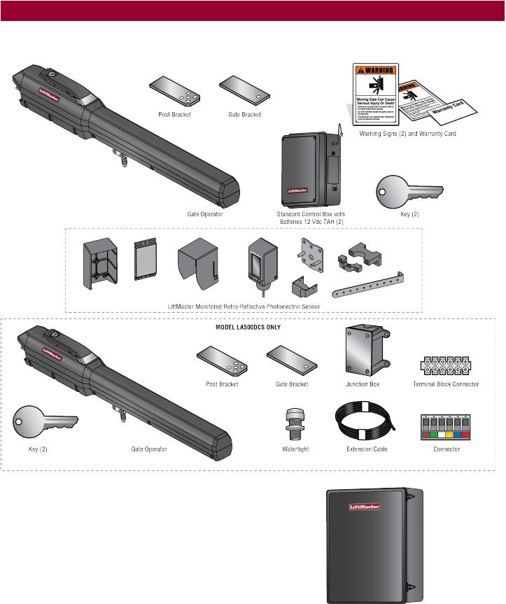
Carton Inventory
NOT SHOWN: Documentation packet and hardware bag
Optional Accessories (not provided)
Large Metal Control Box (Model LA500CONTXLMUL)
Ideal for installations that require additional room in the control box (batteries not included).
Large Metal Control Box for Solar Applications (Model XLSOLARCONTUL)
Required for solar installations (batteries not included). Requires two 33AH batteries, battery tray, and solar battery harness, see Accessories.
6
INTRODUCTION
Operator Specifications
Usage Classification |
Class I, II, III, & IV |
Main AC Supply |
120 Vac, 2 Amps (8 Amps including Accessory Outlets) |
|
OR |
|
240 Vac, 1 Amp |
System Operating Voltage |
24 Vdc Transformer Run / Battery Backup |
Accessory Power |
24 Vdc, 500mA max. for ON + SW (switched) |
Solar Power Max |
24 Vdc at 60 watts max. |
Maximum Gate Weight/Length |
1600 lbs. (725.7kg) / 8 ft (2.4 m) |
|
800 lbs. (362.9 kg) / 16 ft (4.9 m) |
|
600 lbs. (272.2 kg) / 18 ft (5.5 m) |
90 Degree Travel Time* |
15-18 seconds |
Maximum Travel Range* |
115 degrees |
Maximum Daily Cycle Rate |
300 cycles / day |
Maximum Duty Cycle |
Continuous |
Operating Temperature |
-40°C to 60°C (-40°F to 140°F) |
Expansion Board |
Provided |
External Entrapment Protection Device Inputs (non- |
Main board - up to 2 close entrapment protection devices and 1 open entrapment |
contact and/or contact) |
protection device. |
|
Expansion board - up to 3 entrapment protection devices configurable to either close or |
|
open direction and up to 4 edge sensors using wireless edge sensor kit model LMWEKITU. |
|
|
*Travel time and range are affected by A and B mounting dimensions, see INSTALLATION.
7

INTRODUCTION
Site Preparation
Check the national and local building codes BEFORE installation.
Trench
Trench and install conduit. Before trenching, contact underground utility locating companies. Conduit must be UL approved for low and high voltage.
Safety
Entrapment protection devices are required to protect against any entrapment or safety conditions encountered in your gate application. Install a warning sign (two provided) on the inside and outside of the property, where easily visible.
Additional Accessories
The vehicle loops allow the gate to stay open when vehicles are obstructing the gate path. Suggested for vehicles 14 feet (4.27 m) or longer. Vehicle loops are not required but are recommended. Before installing your Access Control Device(s) be sure to complete a site survey and determine the best device for your site needs.
Gate
Gate must be constructed and installed according to ASTM F2200 standards (refer to page 4). Gate must fit specifications of operator (refer to specifications).
Check your gate
Gate MUST be level. Gate and gate post MUST be plumb. Gate MUST have a smooth bottom edge, no protrusions should exist.
Remove ANY/ALL wheels from the bottom of gate.
Gate MUST NOT hit or drag across ground
Gate MUST swing freely and be supported entirely by its hinges.
8
INSTALLATION
•To AVOID damaging gas, power or other underground utility lines, contact underground utility locating companies BEFORE digging more than 18 inches (46 cm) deep.
•ALWAYS wear protective gloves and eye protection when changing the battery or working around the battery compartment.
Installation Tips
Do's
•Weld a horizontal bar across entire gate on any installation for strength. Make sure that the operator is mounted level or it will not function properly.
•Make sure there is slack in the operator cable.
•The operator can be mounted on top of the gate frame.
•The operator must be installed at least 12" (30 cm) from the ground.
Don'ts
•DO NOT install upside down.
•DO NOT install next to sprinklers or any area that may expose the bottom of operator to water.
•DO NOT install on uphill or downhill gates.
•DO NOT install on ANY pedestrian passageways, doorways, or gates.
•DO NOT over-bend the operator cable. Doing this will cause the wires to eventually break.
•DO NOT weld the crossbar on just a few pickets, or they could bend.
9
INSTALLATION
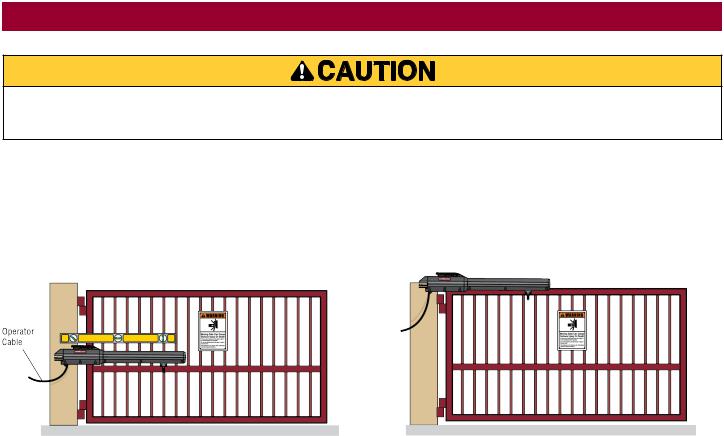
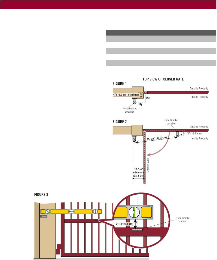
Step 1 Position the Brackets
If this operator is a replacement for a Miracle-One™ operator, use the existing post bracket and gate bracket. Remove the Miracle-One™ operator from the brackets and proceed to the next step.
If your application is Push-to-Open, refer to the illustrations in the Appendix.
The measurements shown below are typical for a standard installation. Your installation may be different. The gate bracket MUST be installed in an area that can withstand heavy forces. Additional reinforcement steel plates may be necessary for mounting.
1.Close the gate.
2.Choose a vertical mounting location for the post bracket.
3.Place a measuring tape under the center of the gate hinge point and measure out dimension A (see chart).
4.Use a screwdriver or dowel rod to temporarily mark the location of the first measurement (Figure 1).
5.Measure out dimension B (see chart) from the previous mark. Use a screwdriver to mark the location of the second measurement (Figure 1).
6.Align the post bracket as close as possible above the screwdriver or dowel rod and tack weld the post bracket in the desired vertical position.
7.Position a level on the post bracket and measure 35-1/2" (90.2 cm) over from the center hole of the post bracket and mark the location on the gate (Figure 2).
8.Measure 2-1/4" (6.4 cm) down from the previous mark and center the bracket on this mark (Figure 3). Tack weld the gate bracket in this position.
NOTES:
•There should only be a maximum of 4" (10.2 cm) from the center of the hinge to the edge of the post or column (Figure 1). If the distance is greater than 4" (10.2 cm) entrapment protection for this area is required.
•While the gate is in the fully open position, the operator needs a clearance of 11-1/4" (28.6 cm) as shown (Figure 2).
NOTE: The ideal installation measurements are A = 7-3/4" (19.7 cm) and B = 8- 1/2" (21.6 cm). If different measurements are used, the sum of A and B cannot be greater than 18" (45.7 cm).
|
DIMENSION CHART |
|
|
|
|
A |
|
B |
|
|
|
7-3/4" (19.7 cm) |
|
8-1/2" (21.6 cm) |
|
|
|
8-1/2" (21.6 cm) |
|
7-3/4" (19.7 cm) |
|
|
|
9" (22.9 cm) |
|
9" (22.9 cm) |
|
|
|
9" (22.9 cm) |
|
8-1/2" (21.6 cm) |
|
|
|
7-1/2" (19.1 cm) |
|
7-1/2" (19.1 cm) |
|
|
|
10
INSTALLATION
Step 2 Attach the Brackets
1.Insert the key into the lock and turn it 180 degrees counterclockwise. Turn the release lever 180 degrees counterclockwise. The operator is now in manual mode.
2.Position the operator on the brackets and make sure the operator is level and positioned correctly on the gate.
3.Remove the operator from the gate.
4.Completely weld around the post bracket and gate bracket.NOTE:
Brackets may need additional reinforcement by welding flat stock as shown.
5.Attach the operator to the post bracket with the bolt, mounting plate, and nut as shown.
6.Attach gate bracket to operator with the bolt, washer, and nut as shown. Tighten the nut until it reaches the bottom of the gate bracket, then turn the nut a half turn, making sure not to overtighten. Make sure the trolley does not reach the fully open or fully closed position.
NOTE: Extra force may be needed to move the trolley back and forth.
For dual gate applications, repeat the previous installation steps to install the second operator.
11
INSTALLATION
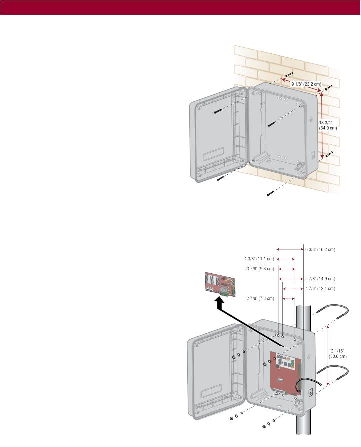
Step 3 Install the Control Box
Standard Control Box
The control box MUST be mounted within 5 feet (1.52 m) of the gate operator. Mount the control box as high as possible for best radio reception. Make sure the control box is level.
NOTE: The expansion board DOES NOT need to be removed for a wall or column mount installation.
1.Remove the screws and open the control box.
2.Disconnect the "Main Board" connector from the expansion board.
3.Remove the expansion board by removing the screws.
4.Select the mounting holes (according to your application) and remove the knockouts using a screwdriver and hammer.
5.Secure the control box to mounting surface.
A.Wall or Column: Use the provided screws (4).
B.Post: Use U-bolts and rubber washers (not provided) to ensure a watertight seal. Make sure the U-bolts do not protrude more than 3/4 inch from the control box because this can short the control board.
6.Reinstall the expansion board and connect the "Main Board" connector to the expansion board.
12
INSTALLATION
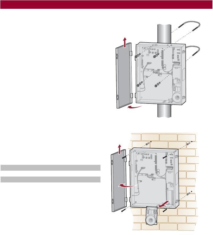
Large Metal Control Box
The control box MUST be mounted within 5 feet (1.52 m) of the gate operator. Mount the control box as high as possible for best radio reception. Make sure the control box is level.
NOTE: The Large Metal Solar Control Box (Model XLSOLARCONTUL) does not have the electrical outlets or the expansion board shown in the images.
Wall or Column Mount
1.Open the control box. The control box door may be removed by opening the door 90°. Lift the door from the hinges and set aside until the installation is complete.
2.Remove the toroid assembly from the control box by loosening the three screws and lifting the assembly up and out.
3.Use knock outs located at the 4 corners of the control box and knock out using a screwdriver and hammer.
4.Secure the control box to mounting surface using the provided screws (4).
Post Mount
NOTE: The post mount option is not recommended for the 33AH battery application.
1.Open the control box. The control box door may be removed by opening the door 90°. Lift the door from the hinges and set aside until the installation is complete.
2.The control box can be mounted to a post with 'U' bolts (refer to chart). The knock out will accommodate a 3/8" diameter 'U' bolt. Select center mounting holes (top and bottom) and knock out using a screwdriver and hammer.
3.Secure the control box to mounting surface with U-bolts and rubber washers (not provided) to ensure a watertight seal.
TYPE AND SIZE |
'U' BOLT OPENING |
|
|
Standard 3" Round Pipe |
3-1/2" |
|
|
Standard 4" Square Post |
4" |
|
|
Standard 6" Square Post |
6" |
|
|
Wall or Column Mount
Post Mount
13
INSTALLATION
To reduce the risk of SEVERE INJURY or DEATH:
•ANY maintenance to the operator or in the area near the operator MUST NOT be performed until disconnecting the electrical power (AC or solar and battery) and locking-out the power via the operator power switch. Upon completion of maintenance the area MUST be cleared and secured, at that time the unit may be returned to service.
•Disconnect power at the fuse box BEFORE proceeding. Operator MUST be properly grounded and connected in accordance with national and local electrical codes. NOTE: The operator should be on a separate fused line of adequate capacity.
•ALL electrical connections MUST be made by a qualified individual.
•DO NOT install ANY wiring or attempt to run the operator without consulting the wiring diagram.
•ALL power wiring should be on a dedicated circuit and well protected. The location of the power disconnect should be visible and clearly labeled.
•ALL power and control wiring MUST be run in separate conduit.
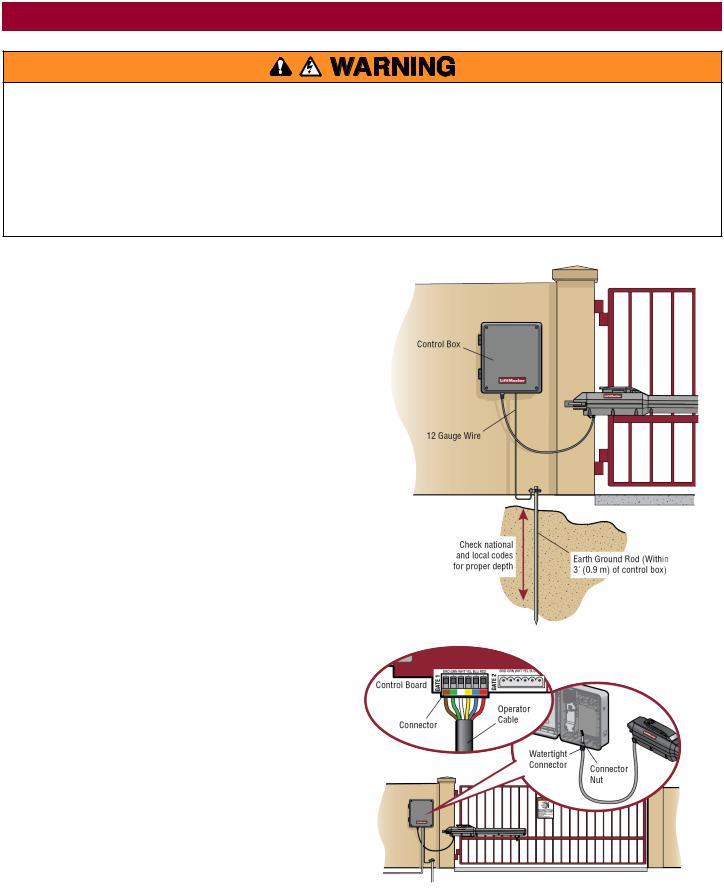
Step 4 Earth Ground Rod
Use the proper earth ground rod for your local area. The ground wire must be a single, whole piece of wire. Never splice two wires for the ground wire. If you should cut the ground wire too short, break it, or destroy its integrity, replace it with a single wire length.
1.Install the earth ground rod within 3 feet (.9 m) of the operator.
2.Run wire from the earth ground rod to the control box.
NOTE: If the operator is not grounded properly the range of the remote controls will be reduced and the operator will be more susceptible to lightning and surge damage.
Step 5 Wire the Operator Arm to the Control Board
1.Choose a knockout in the bottom of the control box.
2.Insert the operator cable through the provided watertight connector.
3.Insert the operator cable and watertight connector into the knockout.
4.Slide the connector nut onto the operator cable.
5.Connect the operator cable wires to the connector according to the colored label on the connector (white to white, red to red, etc.).
6.Plug the connector into the GATE 1 terminal on the control board as shown.
7.Tighten the connector nut.
If installing one operator, proceed to page 18. If installing two operators, go to the following page.
14
INSTALLATION
Step 6 Dual Gate Setup
There are two options for dual gate communication: wired or wireless. Follow the directions according to your application. Do not use wired and wireless communication simultaneously. Wired dual gate applications will have a longer battery standby time than wireless applications. Wireless dual gates will require the installation of two control boxes, one for each operator arm.
Wireless Setup
Install a second operator arm and control box:
Install a second operator arm and control box by following installation steps 1-5.
To activate the wireless feature:
1.Choose an operator to be the network primary operator. All wireless accessories will need to be programmed to the primary operator.
NOTE: We recommend that all accessories and board configurations are set on the primary operator.
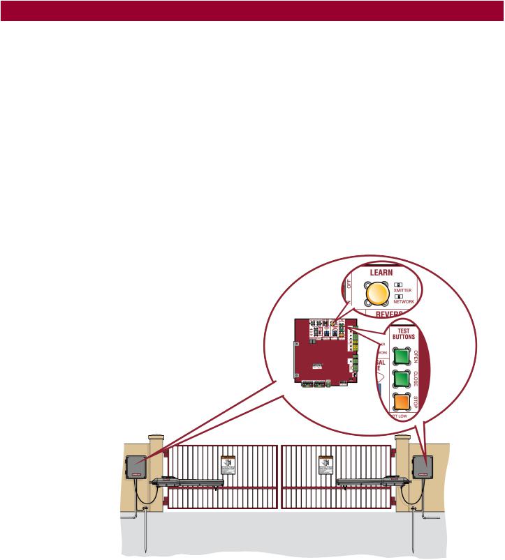
2.Press and release the LEARN button on the primary operator. The green XMITTER LED will light. NOTE: The operator will time out of programming mode after 180 seconds.
3.Press and release the LEARN button again on the primary operator. The yellow NETWORK LED will light.
4.Press and release the OPEN test button to assign this operator as network primary.
5.Press and release the LEARN button on the second operator. The green XMITTER LED will light.
6.Press and release the LEARN button again on the second operator. The yellow NETWORK LED will light.
7.Press and release the CLOSE test button to assign this operator as network second.
Both operators will beep and the yellow NETWORK LEDs will turn off indicating programming is successful.
To deactivate the wireless feature:
1.Press and release the LEARN button on either operator. The green XMITTER LED will light.
2.Press and release the LEARN button again on the same operator. The yellow NETWORK LED will light.
3.Press and hold the LEARN button for 5 seconds. The yellow NETWORK LED will blink (operator will beep) then turn off indicating successful deactivation.
4.Repeat the steps for the other operator.
15
INSTALLATION
Wired Setup
Install a second operator arm:
Install a second operator arm by following installation steps 1-2.
Install the extension cable and junction box:
Before digging, contact local underground utility locating companies.
1.Trench across driveway to bury the extension cable. Use PVC conduit to prevent damage to cables.
2.Open the junction box by removing screws (4) and set aside.
3.Select holes to be used for mounting and knock out using a screwdriver and hammer. Drill two holes in the junction box large enough for the watertight connectors.
4.Mount the junction box within 3 feet (0.9 m) of second operator.
5.Route operator cable and extension cable through watertight connector nut and watertight connector.
6.Insert the cables and watertight connectors into the holes in the junction box.
7.Slide the connector nut onto the operator cable and extension cable.
8.Connect the wires from extension cable and operator cable to the terminal block connector as shown (like-colored wires must face each other).
9.Put wires inside of junction box.
10.Secure operator and extension cables by tightening the connector nut.
11.Reinstall cover.
16
INSTALLATION
Wire the secondary operator arm to the control board:
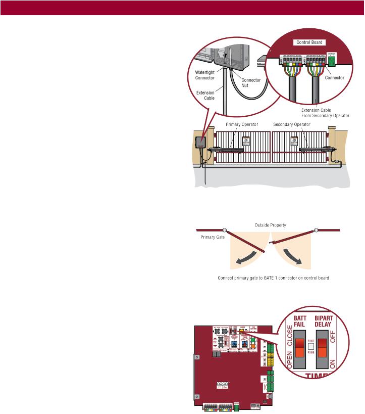
1.Choose a knockout in the bottom of the control box.
2.Insert the extension cable through the watertight connector.
3.Insert the extension cable and watertight connector into the knockout.
4.Slide the connector nut onto the operator cable.
5.Connect the extension cable wires to the connector according to the colored label on the connector (white to white, red to red, etc.).
6.Plug the connector into the GATE 2 terminal on the control board as shown.
7.Tighten the connector nut.
Set the bipart delay (single control box):
Occasionally in dual gate installations, one gate will need to open first and close second. This would happen if there was an ornamental overhang on one gate or if using a solenoid lock, for example. This gate is called the Primary gate and needs to be connected to Gate 1 connections on the control board. Thus, it is preferred that the control box be installed on the same side as this gate. If there is no appropriate location on that side for the control box, then mount the control box on the opposite side, but connect the operator closest to the control box to the Gate 2 connector and the operator on the opposite side to the Gate 1 connector.
1.The BIPART DELAY switch on the control board needs to be set to the ON position.
The illustration shows a dual gate configuration with a decorative overlapping piece on the outside of the gate.
Set the bipart delay (dual control box)
The BIPART DELAY switch is used with dual control box applications and serves two functions:
•BIPART DELAY: The BIPART DELAY is used in applications where a mag-lock, solenoid lock, or decorative overlay would require one gate to close before the other. The control box with the BIPART DELAY switch ON will delay from the close limit when opening and be the first to close from the open limit.
•SYNCHRONIZED CLOSE: The BIPART DELAY is also used in applications where one gate travels a longer distance than the other. To synchronize the closing of the gates, set the BIPART DELAY switch to ON for both control boxes.
17
Loading...