


copyright © 2004 chamberlain professional products - www.eliteaccess.com

T A B L E O F C O N T E N T S
Role of Specifiers..., Role of Dealers.... |
|
|
2 |
|||||||||||||||||||||||||||||||||||||||||
Role of End Users/Home Owners, Horizontal Slide Gate Systems |
|
|
3 |
|||||||||||||||||||||||||||||||||||||||||
Warnings and Precautions |
|
|
|
|
4-6 |
|||||||||||||||||||||||||||||||||||||||
Safely Operating Gate |
|
|
|
|
|
|
7 |
|||||||||||||||||||||||||||||||||||||
Important Notice |
|
|
|
|
|
|
|
8 |
||||||||||||||||||||||||||||||||||||
Configuration and Specifications |
|
|
|
|
|
9 |
||||||||||||||||||||||||||||||||||||||
Warnings and Precautions |
|
|
|
|
|
|
10 |
|||||||||||||||||||||||||||||||||||||
Step 1: Getting Started |
|
|
|
|
|
|
10 |
|||||||||||||||||||||||||||||||||||||
Step 2: Mounting Operator |
|
|
|
|
|
|
11 |
|||||||||||||||||||||||||||||||||||||
Step 3: Chain Installation |
|
|
|
|
|
|
|
11 |
||||||||||||||||||||||||||||||||||||
Step 4: Gate Movement Direction |
|
|
|
|
|
12 |
||||||||||||||||||||||||||||||||||||||
Step 5: Earth Ground Rod |
|
|
|
|
|
|
|
|
13 |
|||||||||||||||||||||||||||||||||||
Step 6: DC Power Supply Connection |
|
|
|
|
14 |
|||||||||||||||||||||||||||||||||||||||
Step 7: “Optional” Solar Panel |
|
|
|
|
|
|
|
15 |
||||||||||||||||||||||||||||||||||||
Step 8: Surge Suppression Terminal Connections |
|
|
|
|
16 |
|||||||||||||||||||||||||||||||||||||||
Step 9: Adjusting Gate Travel Distance |
|
|
|
|
|
17 |
||||||||||||||||||||||||||||||||||||||
Step 10: Timer |
|
|
|
|
|
|
|
|
|
|
|
|
|
|
|
|
17 |
|||||||||||||||||||||||||||
Step 11: 2-Way Adjustable Reversing Sensor |
|
|
|
|
|
18 |
||||||||||||||||||||||||||||||||||||||
Step 12: Mounting Warning Placards |
|
|
|
|
|
|
|
18 |
||||||||||||||||||||||||||||||||||||
“Optional” Fire Release Box |
|
|
|
|
|
|
|
|
|
|
|
|
|
|
|
|
19 |
|||||||||||||||||||||||||||
“Optional” Input Board |
|
|
|
|
|
|
|
|
|
|
|
|
|
|
|
|
|
|
20 |
|||||||||||||||||||||||||
Maglock Wiring Connection |
|
|
|
|
|
|
|
|
|
|
|
|
|
|
|
|
|
21 |
||||||||||||||||||||||||||
“Optional” 12 VDC Photocell Wiring |
|
|
|
|
|
|
|
|
|
|
22 |
|||||||||||||||||||||||||||||||||
3-Push Button Wiring Connection |
|
|
|
|
|
|
|
|
|
|
|
23 |
||||||||||||||||||||||||||||||||
3-Push Button Wiring Master / Slave |
|
|
|
|
|
|
|
|
|
|
24 |
|||||||||||||||||||||||||||||||||
“Optional” Edge Sensor Wiring |
|
|
|
|
|
|
|
|
|
|
|
|
|
|
|
25 |
||||||||||||||||||||||||||||
Single Operator Loop Size and Placement |
|
|
|
|
|
|
|
|
26 |
|||||||||||||||||||||||||||||||||||
Master / Slave Loop Size and Placement |
|
|
|
|
|
|
|
|
|
|
27 |
|||||||||||||||||||||||||||||||||
Loop Installation and Number of Wire Turns |
|
|
|
|
|
|
28 |
|||||||||||||||||||||||||||||||||||||
Wiring Loop Detector to Operator |
|
|
|
|
|
|
|
|
|
|
|
|
|
|
|
29 |
||||||||||||||||||||||||||||
Master and Slave Operators with Timer |
|
|
|
|
|
|
|
|
|
|
|
|
30 |
|||||||||||||||||||||||||||||||
Master and Slave Operators without Timer |
|
|
|
|
|
|
|
|
|
31 |
||||||||||||||||||||||||||||||||||
Control Board Functions |
|
|
|
|
|
|
|
|
|
|
|
|
|
|
|
|
|
|
|
|
|
|
|
|
|
|
|
32 |
||||||||||||||||
LED Descriptions |
|
|
|
|
|
|
|
|
|
|
|
|
|
|
|
|
|
|
|
|
|
|
|
|
|
|
|
|
|
33-34 |
||||||||||||||
Troubleshooting |
|
|
35 |
|||||||||||||||||||||||||||||||||||||||||
How to Reset Breaker Switch |
|
|
|
|
|
|
|
|
|
|
|
|
|
|
|
|
|
|||||||||||||||||||||||||||
How to Check Fuses |
|
|
|
|
|
|
|
|
|
|
|
|
|
|
|
|
|
|
|
|
|
|
|
|
|
|
|
35 |
||||||||||||||||
Gate will not close! |
|
|
|
|
|
|
|
|
|
|
|
|
|
|
|
|
|
|
|
|
|
|
|
|
|
|
|
|
|
36 |
||||||||||||||
Gate will not open! |
|
|
|
|
|
|
|
|
|
|
|
|
|
|
|
|
|
|
|
|
|
|
|
|
|
|
|
|
|
|
36 |
|||||||||||||
If you hear a “BEEP” sound (Audio Alarm) |
|
|
|
|
|
|
37 |
|||||||||||||||||||||||||||||||||||||
Robo Slide Parts |
|
|
|
|
|
|
|
|
|
|
|
|
|
|
|
|
|
|
|
|
|
|
|
|
|
|
|
|
|
|
|
|
|
|
|
|
|
38 |
||||||
Robo Slide Parts List |
|
|
|
|
|
|
|
|
|
|
|
|
|
|
|
|
|
|
|
|
|
|
|
|
|
|
|
|
|
|
|
|
|
|
|
39 |
||||||||
Elite Robo Slide Accessories |
|
|
|
|
|
|
|
|
|
|
|
|
|
|
|
|
|
|
|
|
|
|
|
|
|
|
|
40 |
||||||||||||||||
Owners Checklist of Installation |
|
|
|
|
|
|
|
|
|
|
|
|
|
|
|
|
|
|
|
|
|
|
|
41 |
||||||||||||||||||||
|
|
|
|
|
|
|
|
|
|
|
|
|
|
|
|
|
|
|
|
|
|
|
||||||||||||||||||||||
 Please DO NOT Touch me!.. Unless you are an Authorized Service Technician!
© COPYRIGHT 1992-2003 BY ELITE ACCESS SYSTEMS, INC.
All rights reserved. No part of this manual may be reproduced in any means; graphic, electronic, mechanical, or photocopied without the express written permission of the publisher of this material.
Release 7
7/03
For Toll Free Technical Support: 1-888-ELITE-10
3 5 4 8 3
1

R O L E O F S P E C I F I E R S A N D D E S I G N E R S
Specifiers and designers should design an automatic vehicular gate system to:
•Utilize an operator suited for gate system type, size, frequency of use, location and user population.
•Separate pedestrian access from vehicle access.
•Reduce or eliminate pinch points.
•Reduce risk of entrapment injuries by minimizing all gaps in the gate and enclosing the area of the travel of the gate.
•Secure controls from unauthorized use.
•Locate all controls out of reach from the gate.
•Allow the user full view of the gate when operating.
•Consider special populations, such as children or the elderly.
•Be consistent with DASMA’s Automatic Gate Opener System Safety Guide.
R O L E O F D E A L E R S , I N S TA L L E R S A N D T R A I N E D G AT E S Y S T E M T E C H N I C I A N S
Installers, during the course of the installation proceedings for each job, should:
•Confirm that the gate operator being installed is appropriate for the application.
•Confirm that the gate is designed and built according to current published industry standards.
•Confirm that all appropriate features and accessory devices are being incorporated, including both primary and secondary entrapment protection devices.
•Make sure that the gate works freely before installing the operator.
•Repair or service worn or damaged gate hardware before installing the operator.
•Eliminate all gaps in the sliding gate below a 4 foot height that permit a 2 1/4 inch sphere to pass through any location, including the area of the adjacent fence covered when the gate is in the open position.
•Install the gate operator according to the manufacturer’s installation instructions.
•Adjust the operator clutch or load-sensing device to the minimum force setting that allows reliable gate operation.
•Install operator inside fence line (DO NOT install operator on public side of fence line)
•Install a proper electrical ground to a gate operator.
•Install keypad controls where users cannot touch, or reach through gate while operating controls.
•Install controls where user has full view of gate operation.
•Test all features for proper functions before placing the automatic vehicular gate into service.
•Demonstrate the basic functions and safety features of the gate system to owners/end users/general contractors, including how to turn off power and how to operate the manual disconnect feature.
•Leave safety instructions, product literature, installation manual and maintenance manual with end user.
•Explain to the owners the importance of a service contract that includes a routine re-testing of the entire system including the entrapment protection devices, and explain the need for the owners to insure that this testing is performed routinely.
•Offer the owner/end user a maintenance contract, or contact them regularly to offer maintenance.
2

R O L E O F E N D U S E R S / H O M E O W N E R
End users should be made aware that they must:
•Contact a trained gate systems technician to maintain and repair the gate system (End users should never attempt to repair the gate)
•Retain and utilize the installation and maintenance manual and safety instructions.
•Routinely check of all gate operator functions and gate movement.
•Discontinue use if safety systems operate improperly, the gate is damaged, or the gate is difficult to move.
•Never overtighten the operator clutch of load sensing device to compensate for a damaged or stiff operating gate.
•Keep all obstructions clear of the vicinity of the path of the gate system.
•Actively discourage pedestrian use of the vehicular gate operating system.
•Prevent anyone from playing near any part of the gate system.
•Never allow anyone to climb under, over or through a gate or the adjacent fence area.
•Never allow children to operate gate
•Keep portable controls out of reach of children.
•Never allow anyone to install an operating control within reach of the gate.
•Never allow anyone to install a horizontal slide gate with exposed rollers or openings large enough to allow a sphere of 2 1/4 inches to pass through any portion of the gate below a 4 foot height, including the area of the adjacent fence covered when the gate is in the open position.
•Always be certain that the gate area is clear of pedestrians before operating the gate.
H O R I Z O N TA L S L I D E G AT E S Y S T E M S
•Entrapment Zone Hazard - Body parts may become entrapped between a gate and a stationary object when the gate begins to move, which can result in serious injury or death. Pedestrians must stay clear of the gate path, and any area where gate motion is close to stationary objects.
•Pinch Points Hazard - In open rollers gates, hands can get caught between the top of the gate and top rollers, which can result in serious injury. Feet can be injured in the same manner between the bottom of the gate and bottom rollers. Covers to guard these pinch points should be installed.
•Crush Hazard - In picket gates, body parts positioned between the bars can become seriously mutilated when the gate begins to move, which can result in serious injury or death. If any openings are greater than 2 1/4 inches, a screen should be installed over the gate (in accordance with the provisions of UL 325) to prevent persons from reaching through and/or passing through the gate. In l ike manner, screening should also be applied to the adjacent fence area covered by the gate when in the fully open position.
3

W A R N I N G S A N D P R E C A U T I O N S
IMPORTANT!
Instructions regarding
Robo Slide Installation.
A) Install the gate operator only when: |
|
|
|
1) All openings of a horizontal slide |
gate |
are guarded |
or |
screened from the bottom of the gate |
to a |
minimum of 4 |
feet |
(1.2 m) above the ground to prevent a 2 1/4inch (57.15 mm)
diameter sphere from passing through |
the |
openings |
anywhere in the gate, and in that portion |
of the |
adjacent |
fence that the gate covers in the open position. |
|
|
2)All exposed pinch points are eliminated or guarded, and
3)Guarding is supplied for exposed rollers.
B)The operator is intended for installation only on gates used for vehicles. Pedestrians must be supplied with a separate access opening.
C)The gate must be installed in a location so that enough clearance is supplied between the gate and adjacent structures when opening and closing to reduce the risk of entrapment.
D)The gate must be properly installed and work freely in both directions prior to the installation of the gate operator.
E)Controls must be far enough from the gate so that the user is prevented from coming in contact with the gate while operating the controls.
4

W A R N I N G S A N D P R E C A U T I O N S
F)For a gate operator utilizing a non-contact sensor such as a photo beam:
1)See instructions on the placement of non-contact sensor for each type of application.
2)Care shall be exercised to reduce the risk of nuisance tripping, such as when a vehicle trips the sensor while the gate is still moving.
3) One or more non-contact sensors shall be located where the risk of entrapment or obstruction exists, such as the perimeter reachable by a moving gate or barrier.
G) For a gate operator utilizing a contact sensor such as an edge sensor:
1) One or more contact sensors shall be located at the leading edge, trailing edge and postmounted both inside and outside of a vehicular horizontal slide gate.
2)A hardwired contact sensor shall be located and its wiring arranged so that the communication between the sensor and the gate operator is not subjected to mechanical damage.
3)A wireless contact sensor such as the one that transmits radio frequency (RF) signals to the gate operator for entrapment
protection functions shall be located where the transmission of the signals are not obstructed or impeded by building structures, natural landscaping or similar obstruction. A wireless contact sensor shall function under the intended end-use conditions.
5

W A R N I N G S A N D P R E C A U T I O N S
IMPORTANT SAFETY INSTRUCTIONS
WARNING - To reduce the risk of Injury or Death:
1.READ AND FOLLOW ALL INSTRUCTIONS.
2.Never let children operate or play with gate controls. Keep the remote control away from children.
3.Always keep people and objects away from the gate.
NO ONE SHOULD CROSS THE PATH OF THE MOVING GATE!
4.Test the gate operator monthly. The gate MUST reverse on
contact with a rigid object or stop when an object activates the non-contact sensors. After adjusting the force or the limit of travel, retest the gate operator, Failure to adjust and retest the gate operator properly can increase the risk of injury or death.
5.KEEP GATES PROPERLY MAINTAINED. Read the manual. Have a qualified service person make repairs to the gate or gate hardware.
6.The entrance is for vehicles only. Pedestrians must use separate entrance.
7.SAVE THESE INSTRUCTIONS.
6

S A F E L Y O P E R A T I N G G A T E
 Owners must never let pedestrians cross the path of a moving gate!
 Owners must never allow anyone to hang or ride on the gate!
 Owners must never mount any gate operating device near the gate's path!
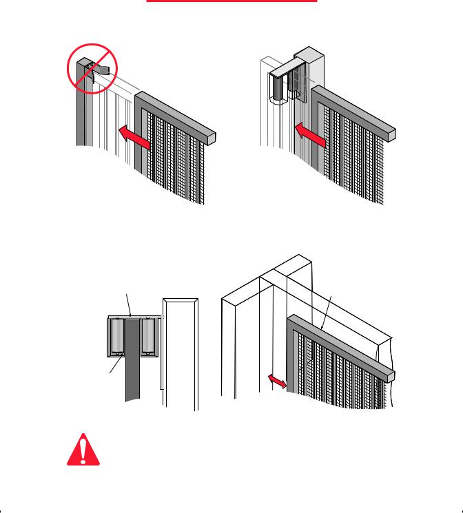
I M P O R T A N T N O T I C E
IMPORTANT! Because the coasting distance may vary due to changes in temperature, Elite does NOT recommend the installation of a stop or catch post in front of the gates path. To do so will cause the gate to hit the post in certain instances.
Incorrect |
Correct |
Non-Pinch
Rollers
Closing |
Closing |
Elite only recommends installation of catch rollers on the side of a catch post or wall with a minimal distance of half an inch between the rollers and gate. Also when fully open the end of the sliding gate must stop at least five inches from a wall.
1/4" Clearance from Top of Gate |
Gate in Fully |
Opened Position |
Non-Pinch |
|
|
Rollers |
|
|
|
Wall |
|
1/2" Clearance |
Wall |
5" |
Between Gate |
|
|
and Rollers |
|
|
|
Gate |
|
|
Minimum of 5" Clearance Between |
|
|
Gate and Wall or Other Object |
|
For safety reasons, a physical stop MUST be installed on the gate prior to installation of the gate operator. This will assure that the gate does not
CAUTION exceed movement limits and derail while opening or closing fully.
8
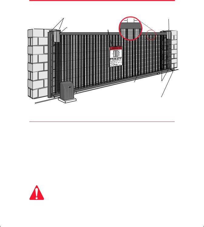
C O N F I G U R A T I O N A N D S P E C I F I C A T I O N S
All “Pinch Points” MUST have protective safety devices.
Sensor Edges |
Warning Placards |
3" Max. Width |
Non-Pinch |
||
|
Permanently Mounted |
Rollers |
Non-Pinch |
on Both Sides |
|
Rollers |
of Gate |
|
(2"x 2" Screen)
Weld Physical Stops on
Both Ends of Gate Rail
Recommended Gate Setup Configuration
Robo Slide Specifications:
Gate Speed – 11 inch per second
Maximum Gate Length – 20 feet
Maximum Gate Weight – 800 pounds
Maximum Cycles – 70 cycles per day with Elite's Plug-In Transformer.
–Solar power cycles per day varies, Contact Elite for more Information
–Battery back-up cycles (50 cycles total)
AC Power Supply – 18 VAC 2.0 Amp Plug-In Transformer (Elite Part # A POW-1)
AC Power Supply Wire – 14 gauge or greater landscape lighting cable rated for direct burial and 300 watts at maximum length of 1000 ft
DC Power Supply – Built-in, back-up for AC or Solar power failure only Solar Power – Optional (Elite Part # SOLAR 3)
Be sure to read and follow all Elite's instructions before installing and operating any Elite product. Always disconnect the gate operator's power source before repairs are attempted. Elite Access Systems, Inc. is not responsible for improper installation or
CAUTION failure to comply with local building codes.
9
R E A D E N T I R E O W N E R S M A N U A L B E F O R E I N S TA L L AT I O N
Model:
Robo Slide For Single Home Applications.
DO NOT Use for Apartment or Condominium Applications.
Warnings and Precautions
CAUTION
1. Do not tighten chain too tight
2. Use proper type of wheels - only 4" steel wheels with high speed ball bearings 3. Do not use a 12V transformer - use only 18 VAC 2.0 Amp
4. Do not install as a rear-mount installation
5. Use only 14 gauge or greater landscape lighting cable rated for direct burial and 300 watts
STEP 1: Getting Started
This gate operator is designed for single home application, or for limited commercial applications. An example of a commercial application would be a factory facility with limited cycles per day, using a plug in transformer or solar panel.
10

S T E P B Y S T E P I N S T A L L A T I O N
STEP 2: Mounting Operator
Pour concrete bed for Robo Slide. Minimum size of bed is 20" x 15" x 20"d. Suggested installation for bolts is 1/2" x 3 1/2" (for red-head fastener).
Red Head Fastener
1/2" x 3 1/2"
Low Voltage
Power Supply Line
 6" AboveGround
10"
20"
8"
Concrete
(Reinforced Recommended) 
20"
15"
STEP 3: Chain Installation
Minimum space between gate and output sprocket must be 4". After you position the gate operator, bolt-down the operator to the concrete bed. Make certain that the concrete bed is solid.
Correct Chain Installation |
Incorrect Chain Installation |
Too High
Too Low
Back of Gate |
Front of Gate |
Gate |
Gate |
4" Minimum |
|
|
|
|
|
|
|
|
|
|
|
|
|
|
|
|
|
|
|
|
|
|
|
|
|
|
|
|
|
|
|
|
|
|
|
|
|
|
|
|
|
|
|
|
|
|
|
|
|
|
|
|
|
|
|
|
|
|
|
|
|
|
|
|
|
|
|
|
|
|
|
|
|
|
|
|
|
|
|
|
|
|
|
|
|
|
|
|
|
|
|
|
|
|
|
|
|
|
|
|
|
|
|
|
|
|
|
|
|
|
|
|
|
|
|
|
|
|
|
|
|
|
|
|
|
|
|
|
|
|
|
|
|
Correct Chain Spacing |
Incorrect Chain Spacing |
||||||||||||||||||||
11
S T E P B Y S T E P I N S T A L L A T I O N
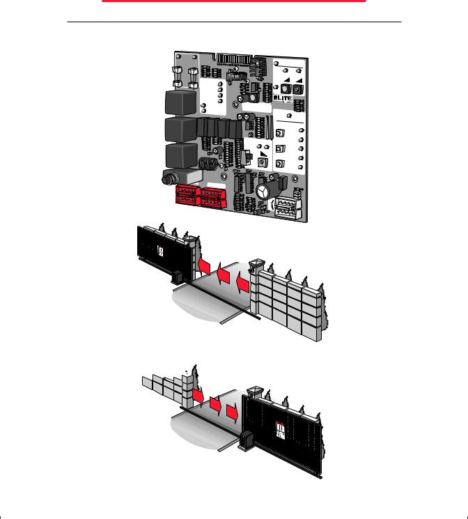
STEP 4: Gate Movement Direction
Plug in the motor harness wires to the left (Socket 1) if your gate, from the inside of the property, opens to the left. Plug into the right (Socket 2) if the gate opens to the right.
CHECK |
|
|
|
|
|
|
|
|
|
FUSE |
BOARD |
|
|
|
|
|
|
|
|
CHARGING |
|
|
|
|
|
SYSTEM ON |
|||
POWER |
POWER |
|
|
|
|
|
|||
|
|
|
J2 |
|
|
|
|||
|
|
|
|
|
|
|
|
|
|
|
|
|
|
|
|
|
ALARM |
REVERSE |
|
|
|
|
|
|
|
|
SENSOR |
SENSOR |
|
|
|
OVERLOAD |
|
|
|
|
HEAVY |
|
|
|
|
|
|
|
|
GATE |
|
|
|
|
|
|
|
|
|
|
|
|
|
|
|
POWER |
|
|
|
|
|
|
|
|
|
CHARGE OK |
|
|
|
|
|
|
|
|
|
BATTERY LOW |
|
|
|
|
|
|
|
|
|
OPEN RELAY |
|
|
|
OPERATOR v |
5M |
||
|
|
CLOSE RELAY |
|
|
|
MADE IN USA |
|||
|
|
|
|
|
|
|
|
||
|
|
|
|
|
|
|
CENTRAL |
CONTROL |
|
|
|
|
|
|
|
|
|
|
FIRE |
|
|
|
|
|
|
|
OPEN |
|
DEPT |
|
|
|
|
|
|
|
|
STRIKE |
|
|
|
|
|
|
|
|
|
|
|
|
|
|
|
|
|
UP |
|
|
OPEN |
|
|
|
|
|
TIMER |
PW |
|
SAFETY |
|
|
|
|
|
|
|
STOP |
|
||
|
|
|
|
|
ON |
|
|
LOOP |
|
|
|
|
|
|
|
|
|
||
|
|
|
|
|
|
60 |
0 |
|
EXIT |
|
|
|
|
|
|
|
|
LOOP |
|
|
|
|
|
|
|
|
CLOSE |
|
|
|
|
|
|
|
OFF |
|
RADIO |
||
|
|
|
|
|
|
|
|
|
REC |
|
|
OPEN |
TO RIGHT |
|
|
|
|
|
|
|
|
|
|
|
|
|
|
|
|
Socket 1 |
Socket 2 |
|
|
|
W1 |
|
|
||
|
|
|
|
|
|
||||
|
|
|
|
|
|
|
|
||
|
|
Open |
to |
Left |
|
|
|
||
|
|
|
|
|
|
|
|||
|
|
|
|
|
OUT |
||||
|
|
|
|
|
|
|
|||


 Open to Right
OUT
IN
12
 Loading...