


 ®
®
™
I n s t r u c t i o n M a n u a l
CSW200UL™ SERIES
H I G H T R A F F I C C O M M E R C I A L G A T E O P E R A T O R
UL325 UL991
compliant compliant
LISTED
installation instructions and manual book for architects, general contractors and dealers
© 2005 the chamberlain group, inc. – all rights reserved
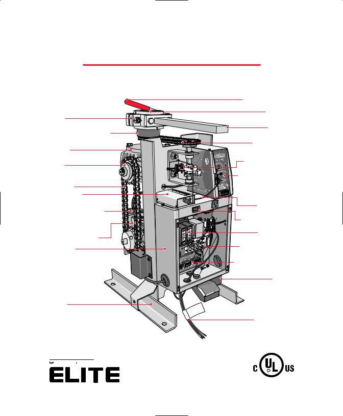
C S W 2 0 0 U L ™
O v e r v i e w
Cludge
Pg. 17
Limit Switch Chain Sprocket |
Gear Box
Clutch
Pg. 21
Chain Drive
Radio Receiver
Pg.25
Optional Factory Installed |
DC2000 Battery Back-Up Motor |
Models DC and DCH Only |
Gear Reducer 40-30:1
W4
Control Box
Optional Factory Installed Heater 
Models H and DCH Only
Pg.33
Chassis
EMERGENCY RELEASE
Pg.29
Output Shaft
Pg.17
Output Arm
Pg.16
Limit Switch Chain
Limit Switch Assembly
Pg.20
|
Optional Factory Installed |
|
DC2000 Battery |
|
Back-Up Controller |
|
Models DC and DCH Only |
|
Pg.30 |
N |
DC2000 Harness |
OFF O |
Pg.30 |
|
Operator ON OFF Switch
Optional Plug-In
Loop Detectors
Pg.39
 OmniControl™ Board
Surge Suppressor Terminal |
Pg.19 |
UL Alarm
Pg.27

 Built-In Reset Button
Pg.26
|
ONC |
|
CAUTIeutr |
||
|
|
VA |
120 |
al |
|
ck |
N |
nd |
Bla e |
|
rou |
hit |
G |
|
W |
|
|
Green |
|
|
CSW Power Wires
Pg.18


 ®
®
™ |
LISTED |
1
Table Of Contents
T A B L E O F C O N T E N T S
Safety Instructions
Role of Specifiers and Designers |
4 |
Role of Dealers, Installers and Trained Gate System Technicians |
4 |
Role of End Users / Home Owners |
5 |
Swing Gate Systems |
5 |
UL Listings |
6-9 |
Warnings and Precautions |
10 |
Installation
Recommended Setup and Operator Specifications |
11 |
Concrete Pad & Arm Attachment |
12 |
Standard Installation Layout |
13 |
Compact Installation Layout |
14 |
Optional Swivel Arm Installation (Uphill Driveways) |
15 |
Optional Post Mounting Plate |
15 |
Arm Installation |
16 |
Adjustment of Output Shaft |
17 |
How to Connect Power (110 V) |
18 |
Surge Suppressor Terminal Input Connections (Wiring Optional Equipment) |
19 |
Choosing Movement Direction (Open Left or Right) |
20 |
Adjusting Gate Traveling Distance (Limit Switches) |
20 |
Clutch Adjustment |
21 |
Mounting Required Warning Signs |
21 |
Two-Way Adjustable Reversing Sensor |
22 |
Adjustable Timer |
22 |
Master / Second Operators with Timer On |
23 |
Master / Second Operators with Timer Off |
24 |
Radio Receiver Programming |
25 |
Built-In Reset Button |
26 |
Remove Control Board |
27 |
Audio Alarm |
27 |
Solenoid/Maglock J3 Plug Connection |
28 |
|
|
EMERGENCY RELEASE |
29 |
Please DO NOT Touch me!.. Unless you are an Authorized Service Technician!
© 2005 The Chamberlain Group, Inc.
All Rights Reserved.
For Technical Support: 1-800-528-2806
2

T A B L E O F C O N T E N T S
Optional Factory Installed Equipment
Optional Factory Installed DC2000 Back-Up Connection. Models DC and DCH Only |
30 |
Wiring Optional Devices to DC2000 |
31 |
Wiring Optional Safety Devices to DC2000 |
32 |
Optional Factory Installed Heater. Models H and DCH Only |
33 |
Optional Omni Option Board
Optional Omni Option Board Description |
34 |
Optional Master/Second Connection |
34 |
Optional House Alard/Proximity Switch Connection |
35 |
Optional 3 Push Button Station Connection |
36 |
Optional Stop Button Alarm Shut-Off Connection |
36 |
Optional Solenoid Connection |
37 |
Optional Maglock Connection |
37 |
Optional Relay Adapter
Optional Solenoid/Maglock Connection |
38 |
Optional Loop Detectors and Loop Setup
Optional Plug-In Loop Detectors |
39 |
Optional External Loop Detectors |
40 |
Single Operator Loop Sizes and Placement |
41 |
Master/Second Loop Sizes and Placement |
42 |
Loop Installation and Number of Wire Turns |
43 |
Optional Safety Equipment
Optional Photo Electric Sensors “Safety” Connection |
44 |
Optional Secondary Entrapment Protection Connection (Non-Contact Sensor) |
45 |
Optional Secondary Entrapment Protection Connection (Contact Sensor) |
46 |
Optional Products
Optional Products |
47 |
|
Troubleshooting |
|
|
|
Troubleshooting Table |
48 |
|
|
Troubleshooting LED Information |
49 |
|
|
Repair Parts |
|
|
|
Parts Illustrations |
50 |
|
|
Parts List |
51 |
|
|
Maintenance |
|
|
|
Maintenance |
51 |
|
|
|
|
|
Property Owners Checklist of Installation |
52 |
|
|
Contents Of Table
3

R O L E O F S P E C I F I E R S A N D D E S I G N E R S
Specifiers and designers should design an automatic vehicular gate system to:
•Incorporate UL 325 compliant equipment.
•Utilize an operator suited for gate system type, size, frequency of use, location and user population. (Refer to UL 325 for usage class definitions)
•Separate pedestrian access from vehicle access.
•Reduce or eliminate pinch points.
•Reduce risk of entrapment injuries by minimizing all gaps in the gate and enclosing the area of the travel of the gate.
•Secure controls from unauthorized use.
•Locate all controls out of reach from the gate.
•Allow the user full view of the gate when operating.
•Consider special populations, such as children or the elderly.
•Conspicuously display all warnings and instructions.
•Be consistent with DASMA’s Automatic Gate Opener System Safety Guide.
R O L E O F T R A I N E D
D E A L E R S , I N S T A L L E R S A N D G A T E S Y S T E M T E C H N I C I A N S
Installers, during the course of the installation proceedings for each job, should:
•Confirm the gate operator being installed is appropriate for the application.
•Confirm the gate is designed and built according to current published industry standards.
•Confirm all appropriate features and accessory devices are being incorporated, including both primary and secondary entrapment protection devices.
•Make sure the gate works freely before installing the operator.
•Repair or service worn or damaged gate hardware before installing the operator.
•Adjust the operator clutch or load-sensing device to the minimum force setting that allows reliable gate operation.
•Install operator inside fence line (DO NOT install operator on public side of fence line)
•Install a proper electrical ground to a gate operator.
•Install keypad controls where users cannot touch, or reach through gate while operating controls.
•Install controls where user has full view of gate operation.
•Install all warning signs (In accordance with UL 325) on both sides of the gate to warn persons in the area of potential hazards associated with automatic vehicular gate operation.
•Test all features for proper functions before placing the automatic vehicular gate into service.
•Demonstrate the basic functions and safety features of the gate system to owners/end users/general contractors, including how to turn off power and how to operate the manual disconnect feature.
•Leave safety instructions, product literature, installation manual and maintenance manual with end user.
•Explain to the owners the importance of a service contract that includes a routine re-testing of the entire system including the entrapment protection devices, and explain the need for the owners to insure that this testing is performed routinely.
•Offer the owner/end user a maintenance contract, or contact them regularly to offer maintenance.
4

R O L E O F E N D U S E R S / H O M E O W N E R
End users should be made aware that they must:
•Contact a trained gate systems technician to maintain and repair the gate system. (End users should never attempt to repair the gate)
•Retain and utilize the installation and maintenance manual and safety instructions.
•Routinely check all gate operator functions and gate movement.
•Discontinue use if safety systems operate improperly, the gate is damaged, or the gate is difficult to move.
•Never over tighten the operator clutch on load sensing device to compensate for a damaged or stiff operating gate.
•Prominently display and maintain warning signs on both sides of the gate.
•Keep all obstructions clear of the vicinity of the path of the gate system.
•Actively discourage pedestrian use of the vehicular gate operating system.
•Prevent anyone from playing near any part of the gate system.
•Never allow anyone to climb under, over or through a gate or the adjacent fence area.
•Never allow children to operate gate
•Keep portable controls out of reach of children.
•Never allow anyone to install an operating control within reach of the gate.
•Always be certain the gate area is clear of pedestrians before operating the gate.
S W I N G G A T E S Y S T E M S
•Entrapment Zone Hazard - Body parts may become entrapped between a gate and a stationary object when the gate begins to move, which can result in serious injury or death. Pedestrians must stay clear of the gate path, and any area where gate motion is close to stationary objects.
•Pinch Points Hazard - The opening mechanism may have arms that can overlap with a scissoring effect, which can result in serious injury. Pedestrians must stay clear of the opening mechanism at all times, particularly when gate is opening.
Be sure that warning signs are prominently displayed on both sides of the gate and any other place where danger exists.
5

U L L I S T I N G S A N D I N S T R U C T I O N S
Installation Instructions regarding the CSW200UL™
A)Install the gate operator only when:
1)The operator is appropriate for the construction and the usage class of the gate.
2)All exposed pinch points are eliminated or guarded.
B)The operator is intended for installation only on gates used for vehicles. Pedestrians must be supplied with a separate access opening.
C)The gate must be installed in a location so that enough clearance is supplied between the gate and adjacent structures when opening and closing to reduce the risk of entrapment. Swinging gates shall not open into public access areas.
D)The gate must be properly installed and work freely in both directions prior to the installation of the gate operator. Do not over-tighten the operator clutch to compensate for a damaged gate.
E)Controls must be far enough from the gate so the user is prevented from coming in contact with the gate while operating the controls. Controls intended to be used to reset an operator after 2 sequential activations of the entrapment protection device or devices must be located in the line of sight of the outdoor gate or easily accessible controls shall have a security feature to prevent unauthorized use.
F)All warning signs and placards must be installed where visible in the area of the gate. A minimum of two placards must be installed. A placard is to be installed in the area of each side of the gate and be visible to persons located on the side of the gate on which the placard is installed.
6

U L L I S T I N G S A N D I N S T R U C T I O N S
G)For a gate operator utilizing a non-contact sensor such as a photo beam:
1)See instructions on the placement of non-contact sensor for each type of application.
2)Care shall be exercised to reduce the risk of nuisance tripping, such as when a vehicle trips the sensor while the gate is still moving.
3)One or more non-contact sensors shall be located where the risk of entrapment or obstruction exists, such as the perimeter reachable by a moving gate or barrier.
H)For a gate operator utilizing a contact sensor such as an edge sensor:
1)A hardwired contact sensor shall be located and its wiring arranged so that the communication between the sensor and the gate operator is not subjected to mechanical damage.
2)A wireless contact sensor such as the one that transmits radio frequency (RF) signals to the gate operator for entrapment protection functions shall be located where the transmission of the signals are not obstructed or impeded by building structures, natural landscaping or similar obstruction. A wireless contact sensor shall function under the intended end-use conditions.
3)One or more contact sensors shall be located on the inside and outside leading edge of a swing gate. Additionally, if the bottom edge of a swing gate is greater than 6 inches (152 mm) above the ground at any point in its arc of travel, one or more contact sensors shall be located on the bottom edge.
7
U L L I S T I N G S A N D I N S T R U C T I O N S
Important Safety Instructions
 WARNING - To reduce the risk of injury or death:
1)READ AND FOLLOW ALL INSTRUCTIONS.
2)Never let children operate or play with gate controls. Keep the remote control away from children.
3)Always keep people and objects away from the gate.
NO ONE SHOULD CROSS THE PATH OF THE MOVING GATE.
4)Test the gate operator monthly. The gate MUST reverse on contact with a rigid object or stop when an object activates the non-contact sensors. After adjusting the force or the limit of travel, retest the gate operator, Failure to adjust and retest the gate operator properly can increase the risk of injury or death.
5)Use the emergency release only when the gate is not moving. Make sure the power for the gate operator is off.
6)KEEP GATES PROPERLY MAINTAINED. Read the manual. Have a qualified service person make repairs to the gate or gate hardware.
7)The entrance is for vehicles only. Pedestrians must use separate entrance.
8)SAVE THESE INSTRUCTIONS.
8

U L L I S T I N G S A N D I N S T R U C T I O N S
UL Definition of Terms
Gate – A moving barrier such as a swinging, sliding, raising lowering, rolling, or like, barrier, that is a stand-alone passage barrier or is that portion of a wall or fence system that controls entrance and/or egress by persons or vehicles and completes the perimeter of a defined area.
Vehicular swing-gate operator (or system) – A vehicular gate operator (or system) that controls a gate which swings in an arc in a horizontal plane that is intended for use for vehicular entrance or exit to a drive, parking lot, or the like.
UL Gate Classifications
Class I – Residential vehicular gate operator
A vehicular gate operator (or system) intended for use in a home of one-to four single family dwelling, or a garage or parking area associated therewith.


 Class II – Commercial/General access vehicular gate operator
A vehicular gate operator (or system) intended for use in a commercial
location or building such as a multi-family housing unit (five or more single family units) hotel, garages, retail store or other building servicing the general public.
Class III – Commercial/General access vehicular gate operator |
A vehicular gate operator (or system) intended for use in a industrial |
location or building such as a factory or loading dock area or other |
locations not intended to service the general public. |
Class IV – Restricted access vehicular gate operator |
A vehicular gate operator (or system) intended for use in a guarded |
industrial location or building such as an airport security area or other |
restricted access locations not servicing the general public, in which |
unauthorized access is prevented via supervision by security |
personnel. |
9
Warnings and Precautions
W A R N I N G S A N D P R E C A U T I O N S
The CSW200UL™ is for Vehicular Gate Use Only!
NOT for use on any Pedestrian: Gateways, Doorways or Passageways.
Property owners must never let pedestrians cross the path of a moving gate!
Property owners must never mount any gate operating device accessible through the gate!
Property owners must never let anyone hang or ride on the gate!
10
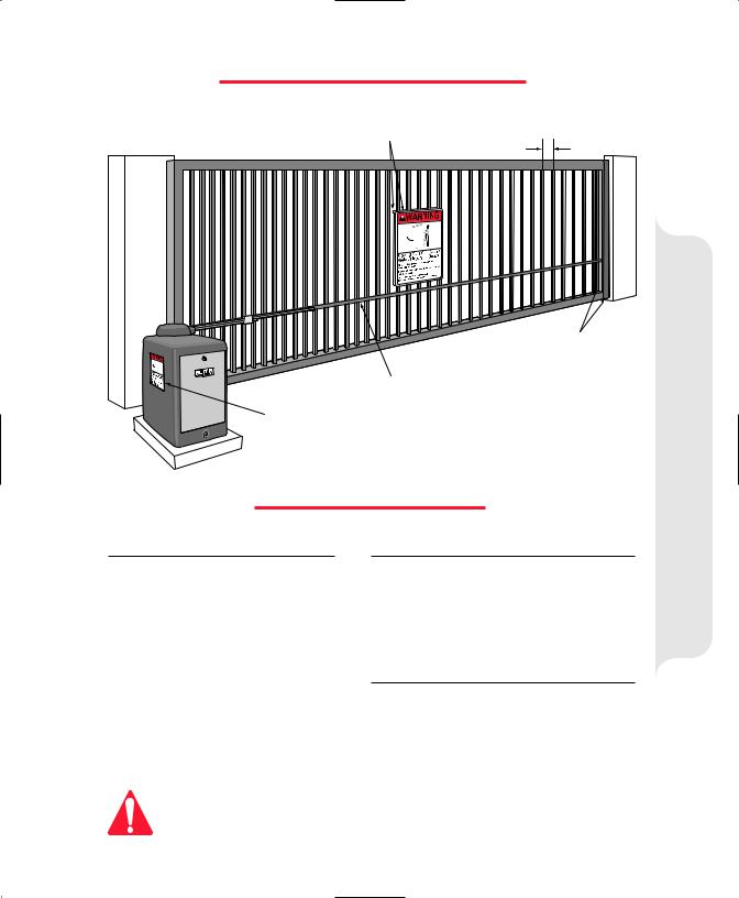
R E C O M M E N D E D S E T U P
All “Pinch Points” MUST have protective safety devices.
Warning Signs Attached on Both Sides of Gate |
4" Max. Width |
Edge Sensors
Warning Sign Clearly
Visible on Operator
 Pedestrians Must have a Separate Walkway!
S P E C I F I C A T I O N S
CSW200UL™, CSW200ULDC™ |
CSW200ULDM™, CSW200ULDMDC™ |
CSW200ULH™, CSW200ULDCH™ |
CSW200ULDMH™, CSW200ULDMDCH™ |
1/2 hp Motor, 120 Vac, 4 Amp. Maximum Gate Length – 20 ft. Maximum Gate Weight – 600 lbs. Maximum Pull – 125 lbs.
CSW200ULST™, CSW200ULSTDC™ CSW200ULSTH™, CSW200ULSTDCH™
Two-1/2 hp Motors, 120 Vac, 4 Amp. Maximum Gate Length – 20 ft. Maximum Gate Weight – 800 lbs. Maximum Pull – 115 lbs.
CSW200UL1HP™
CSW200UL1HPH™
1/2 hp Motor, 120 Vac, 4 Amp. |
Two-1/2 hp Motors, 120 Vac, 7.9 Amps. |
Maximum Gate Length – 20 ft. |
Maximum Gate Length – 22 ft. |
Maximum Gate Weight – 600 lbs. |
Maximum Gate Weight – 1000 lbs. |
Maximum Pull – 125 lbs. |
Maximum Pull – 250 lbs. |
DM -Dual Motor 1HP-One Horse power H-Factory Installed Heater DC-Factory Installed DC2000 Backup System
Be sure to read and follow all Chamberlain Elite and UL instructions before installing and operating any Chamberlain Elite products. the Chamberlain Group, Inc is not responsible for improper installations or failure to comply with local building codes.
Specifications and Setup
11

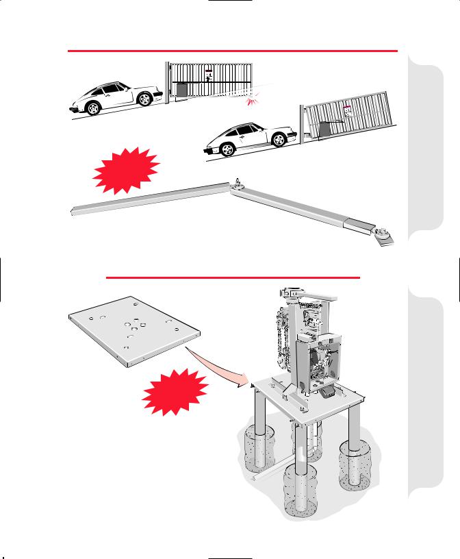
Concrete Pad and Arm Attachment
C O N C R E T E P A D A N D A R M A T T A C H M E N T
Red Head Fastener
1/2" x 3 1/2"
Top View
19"
|
5 1/4" |
|
Box |
|
|
|
|
14" |
3 7/8" |
3 5/8" |
Electronic |
|
|||
|
5 1/4" |
|
Approximate Placement of Conduit
Above |
6 " |
|
Ground |
WARNING! |
|
|
|
|
Below the Frost Line |
|
|
Check all |
|
|
Local Codes |
|
|
|
Concrete Pad |
|
|
or |
|
|
Optional Mounting Plate |
|
|
(See page 15) |
|
|
28" |
DO NOT weld any |
|
24" |
supports to chassis |
|
Chassis must be allowed |
|
|
|
to “flex” during operation |
Sample of Standard Installation (See next page for layout) |
Hinge Center |
|
Drawing not to scale |
Out |
46" |
Post |
|
|
25" |
|
In |
2" |
|
|
35.5" |
11" |
|
|
|
|
|
|
Long Arm |
|
10" |
onal |
Bracket Height |
29.5" |
|
Opti |
|
Short Arm |
|
duct |
Using Elite Standard CSW Arm (Part # Q104) |
|
|
Pro |
28" |
|
|
|
|
|
|
Top of Bracket |
|
|
Concrete Pad |
|
27.5" |
24" |
|
|
||
|
Bottom of CSW |
|
|
|
|
Concrete Pad Height |
|
|
|
12 |
|

S T A N D A R D I N S T A L L A T I O N L A Y O U T
Sample Installation is Shown on Previous Page.
1
Top View of Closed Gate
 1/4
1/4 
 1/4
1/4 
 1/4
1/4 
 Bracket Length
Bracket Position |
Gate Hinge |
Mount bracket at least a quarter of the gate length from the gate hinge.
2
Drawing not to scale
|
|
|
|
|
|
|
|
|
|
|
|
|
|
|
|
|
|
|
|
|
|
|
|
|
|
|
|
|
|
|
|
|
|
Gate |
|
|||
|
|
|
|
|
|
|
|
Open 90° |
|
|||
|
Helpful Layout Note: |
|
|
|
||||||||
|
A) Tack weld bracket in position. |
|
h |
|||||||||
|
|
|
|
|
|
|
|
|
|
|
||
|
B) Close gate, place tape measure |
|
Lengt |
|||||||||
|
|
|
|
|||||||||
|
between Bracket and Output Shaft. |
|
acker t |
|||||||||
|
C) With tape between bracket and |
|
||||||||||
|
|
|
|
|||||||||
|
output shaft, open gate and bend |
|
B |
|||||||||
|
tape until tape is 90° from gate. |
|
|
|
||||||||
|
D) Take measurements of arms |
|
|
|
||||||||
|
from bent tape measure. |
|
|
|
||||||||
|
|
Arm must be 90° from Gate |
|
|||||||||
|
|
|
||||||||||
|
|
|
|
|
|
|
|
|
|
|
|
|
|
|
Caution: DO NOT allow |
|
Bracket |
||||||||
|
|
|
||||||||||
|
|
arms to scissor when open. |
|
|
|
|
||||||
|
|
|
|
|
|
|
|
|
|
|
|
|
|
|
|
|
|
|
|
|
|
|
|
|
|
|
|
|
|
|
|
|
|
|
|
|
|
|
|
|
|
|
|
|
|
|
|
|
|
|
|
|
|
|
|
|
|
|
|
|
|
|
|
|
|
|
|
|
|
|
|
|
|
|
|
|
|
|
|
|
|
|
|
|
|
|
|
|
|
|
|
|
|
|
|
|
|
|
|
|
|
|
|
|
|
|
|
|
|
|
|
|
|
|
|
|
|
|
|
|
|
|
|
|
|
Gate Hinge Center |
||
|
|
|
|
|
|
|
|
|
|||
|
|
|
|
|
|
uimn(Mi |
gthnLe acketrB |
CSW200UL™ in |
|||
|
|
|
|
|
|
||||||
|
|
|
|
|
|
||||||
|
|
|
|
|
|
m) |
Mi |
|
Open Position |
||
|
|
|
|
|
|
|
|
8" nus |
|
||
|
|
|
|
|
|
|
|
|
|
|
|
|
|
|
|
Minimum |
|
|
|
|
|
|
|
|
|
|
|
|
|
|
|||||
|
9" |
|
|
|
|
|
|
||||
|
|
10" |
|
|
|
28" |
|||||
|
|
|
fo |
r Gate |
|
|
|
|
|||
|
|
Clearance |
|
|
|
|
Output Shaft |
||||
|
|
|
|
|
|
|
|
|
|
|
|
|
|
|
|
|
|
|
|
|
|
|
Center |
|
|
|
|
|
|
|
|
|
|
|
|
|
8" |
Minimum to |
avoid |
|
|
|
|||||
|
|
scissoring of a |
rms |
|
|
Arm |
|||||
|
|
|
|
|
|
|
|
|
|
|
|
|
|
|
|
|
|
|
|
|
|
|
|
|
|
|
|
|
|
|
|
|
|
|
|
Arm
 Concrete
 Pad
Pad


 24"
24"
Important Note:
If this dimension is between 20 and 32 inches, “Compact
Installation” is necessary. (Refer to next page)
For technical support please call:
1-800-528-2806
tuLayo ntallationsI drdanSta
13

Compact Installation Layout
C O M P A C T I N S T A L L A T I O N L A Y O U T
Compact Installation Only!
DO NOT Use These Measurements for a Standard Installation.
(For Standard Installation, See Page 12-13)
It is necessary to protect against the entrapment that could occur with this type of installation.
(See Secondary Entrapment Protection Pages 45 and 46)
20"
Minimum
Width
Gate Open |
|
|
|
|
|
|
Gate Closed |
|
|
|
|
|
|
|
|
|
Hinge Center |
Out |
|
|
|
|
|
|
Out |
33" |
In |
|
|
|
|
|
|
In |
|
26.5" |
|
|
|
|
|
|
|
9" |
|
|
|
|
|
|
|
|
|
|
|
|
|
|
|
|
|
23" |
|
|
|
|
|
|
|
|
25.5" |
|
|
|
|
|
|
|
nt |
|
|
|
|
|
|
|
e |
|
|
|
|
|
|
m |
er |
|
||
|
|
|
p |
|
|
|
||
|
|
a |
|
|
g |
|
||
|
tr |
|
|
n |
|
|
||
n |
|
|
a |
|
|
|
||
E |
|
D |
|
|
|
|
||
20" to 32" |
|
|||||||
Cut |
|
|
|
|
|
|
Long Arm |
Cut |
 10"
10" 
 22"
22" 
 4"
4" 

 36"
36" 
Cut |
Short Arm |
 4"
4" 
 20"
20" 
24"
Follow the exact measurements, then cut the standard arm to meet the shorter measurements.
14
O P T I O N A L U P H I L L D R I V E W A Y I N S T A L L A T I O N
Impossible
Gate hits driveway
|
|
al |
Possible |
||
|
ion |
|
|||
t |
|
t |
|
||
Op |
|
|
Special arm and hinges are required |
||
roduc |
|||||
|
|||||
P |
|
|
|
|
|
Part
Uphill Optional
Installation Driveway
O P T I O N A L P O S T M O U N T I N G P L A T E
Part # MPEL |
|
al |
|
|
|
||
|
ion |
|
|
t |
|
t |
|
Op |
|
|
|
roduc |
|||
P |
|
|
|
3“ heavy steel posts are U-bolted to mounting plate and cemented in ground.
Power and control 


 wiring can be run in


separate conduits.
Contact your local dealer for more information.
Post Optional
Plate Mounting
15
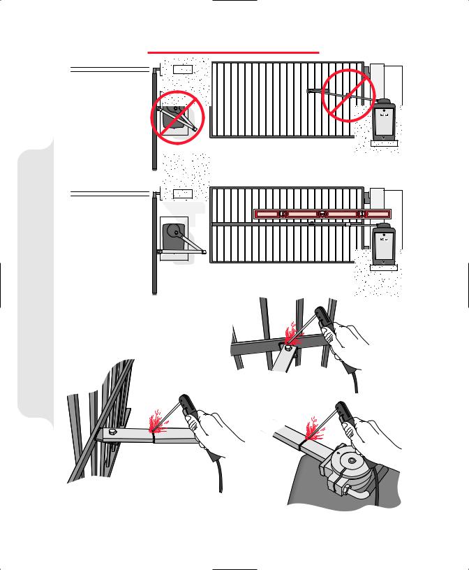
Arm Installation
A R M I N S T A L L A T I O N
Incorrect
Installation
Correct
Installation
Once the gate arm measurements are calculated:
weld the bracket on the gate.
Weld the longer arm..........
........then weld the shorter arm.
Weld Completely Around the Rectangular Tubes
16
 Loading...