


 Logic 3
O W N E R ’ S M A N U A L
A P T
INDUSTRIAL DUTY COMMERCIAL DOOR OPERATOR
This Operator Features
the Enhanced
EN |
|
T |
A |
|
|
M
A
PATENT PENDING
R |
S |
|
T SY |
M
The Maintenance Alert System™ allows the installer to set an internal Maintenance Cycle Counter. The Logic 3 operator incorporates a self-diagnostic feature built into the (MAS) Maintenance Alert System LED. An LED on the 3-button station will signal when the set number of cycles/months is reached or when the operator requires immediate service.
Radio Receiver
Built on Board
2 Y E A R W A R R A N T Y
315MHz
NOT FOR RESIDENTIAL USE

T A B L E O F C O N T E N T S
SPECIFICATIONS
Carton Inventory . . . . . . . . . . . . . . . . . . . . . . . . . . . . . . . . . . . . .3
Operator Dimensions . . . . . . . . . . . . . . . . . . . . . . . . . . . . . . . . . .3
Operator Specifications . . . . . . . . . . . . . . . . . . . . . . . . . . . . . . . .4
PREPARATION
Track Assembly . . . . . . . . . . . . . . . . . . . . . . . . . . . . . . . . . . . . . .5
Powerhead Attachment . . . . . . . . . . . . . . . . . . . . . . . . . . . . . . . .5
Trolley Carriage/Chain Attachment . . . . . . . . . . . . . . . . . . . . . . . .5
INSTALLATION
Mount the Header Bracket . . . . . . . . . . . . . . . . . . . . . . . . . . . . . .6
Mount the Operator . . . . . . . . . . . . . . . . . . . . . . . . . . . . . . . . . . .6
Hang the Operator . . . . . . . . . . . . . . . . . . . . . . . . . . . . . . . . . . . .7
Straight Arm Attachment . . . . . . . . . . . . . . . . . . . . . . . . . . . . . . .7
Entrapment Protection Accessories . . . . . . . . . . . . . . . . . . . . . . .8
ADJUSTMENT
Limit Switch Adjustment . . . . . . . . . . . . . . . . . . . . . . . . . . . . . . .8
Emergency Disconnect System . . . . . . . . . . . . . . . . . . . . . . . . . .9
Brake Adjustment . . . . . . . . . . . . . . . . . . . . . . . . . . . . . . . . . . .10
Clutch Adjustment and Auxiliary Reversal System . . . . . . . . . .10
POWER & GROUND WIRING
Safety Warnings . . . . . . . . . . . . . . . . . . . . . . . . . . . . . . . . . . . .11
Power Wiring Connections . . . . . . . . . . . . . . . . . . . . . . . . . . . .11
Ground Wiring Connections . . . . . . . . . . . . . . . . . . . . . . . . . . .11
CONTROL STATION WIRING & INSTALLATION
Control Wiring Connections . . . . . . . . . . . . . . . . . . . . . . . . . . .12
Mounting Instructions . . . . . . . . . . . . . . . . . . . . . . . . . . . . . . . .12
External Radio Wiring Connections . . . . . . . . . . . . . . . . . . . . . .12
DIAGRAMS
Standard Power & Control Connection Diagrams . . . . . . . . . . .13
1 Phase Wiring Diagram . . . . . . . . . . . . . . . . . . . . . . . . . . . . . .14
Control Board . . . . . . . . . . . . . . . . . . . . . . . . . . . . . . . . . . . . . .15
PROGRAMMING
Control Board Pushbuttons . . . . . . . . . . . . . . . . . . . . . . . . . . . .16
Determine and Set Wiring Type . . . . . . . . . . . . . . . . . . . . . . . . .16
Failsafe Wiring Types . . . . . . . . . . . . . . . . . . . . . . . . . . . . . . . . .17
Self-Monitoring Safety Device Options . . . . . . . . . . . . . . . . . . .17
Programming Remotes . . . . . . . . . . . . . . . . . . . . . . . . . . . .18-19
Maintenance Alert System (MAS) . . . . . . . . . . . . . . . . . . . . . . .20
Mid Stop . . . . . . . . . . . . . . . . . . . . . . . . . . . . . . . . . . . . . . . . . .21
Timer To Close . . . . . . . . . . . . . . . . . . . . . . . . . . . . . . . . . . .21-22
AUTOMATICALLY LEARNED PROGRAMMING
Auxiliary Reversal System/RPM Sensor . . . . . . . . . . . . . . . . . .22
Maximum Run Timer (MRT) . . . . . . . . . . . . . . . . . . . . . . . . . . .23
OPTIONAL PROGRAMMING
Red/Green Warning Light Card . . . . . . . . . . . . . . . . . . . . . . . . .23
Resetting Factory Defaults - Clearing Memory . . . . . . . . . . . . .24
MAINTENANCE SCHEDULE . . . . . . . . . . . . . . . . . . . . . . . .24
TROUBLESHOOTING
Diagnostic Chart . . . . . . . . . . . . . . . . . . . . . . . . . . . . . . . . . . . .25
Troubleshooting Guide . . . . . . . . . . . . . . . . . . . . . . . . . . . . . . . .26
Troubleshooting Error Codes . . . . . . . . . . . . . . . . . . . . . . . . . . .27
Troubleshooting Radio Functionality . . . . . . . . . . . . . . . . . . . . .28
REPAIR PARTS
Electrical Box . . . . . . . . . . . . . . . . . . . . . . . . . . . . . . . . . . . .30-31
Repair Parts Kits . . . . . . . . . . . . . . . . . . . . . . . . . . . . . . . . .32-33
Operator Notes . . . . . . . . . . . . . . . . . . . . . . . . . . . . . . . . . . .34-35
Control Connection Diagram . . . . . . . . . . . . . . . . . . . . . . . . . . .36
 WARNING
Mechanical
 WARNING
Electrical
CAUTION
When you see these Safety Symbols and Signal Words on the following pages, they will alert you to the possibility of serious injury or death if you do not comply with the warnings that accompany them. The hazard may come from something mechanical or from electric shock. Read the warnings carefully.
When you see this Signal Word on the following pages, it will alert you to the possibility of damage to your door and/or the door operator if you do not comply with the cautionary statements that accompany it. Read them carefully.
IMPORTANT NOTES:
•BEFORE attempting to install, operate or maintain the operator, you must read and fully understand this manual and follow all safety instructions.
•DO NOT attempt repair or service of your commercial door and gate operator unless you are an Authorized Service Technician.
C A R T O N I N V E N T O R Y
DESCRIPTION
POWER HEAD ASSEMBLY
OWNER'S MANUAL AND CAUTION LABELS
HARDWARE BOX (INCLUDES FASTENERS, TRACK SPACERS, DOOR ARM ASSEMBLY, FRONT IDLER AND HEADER MOUNTING BRACKET)
AUTO RECONNECT TROLLEY
3-BUTTON CONTROL STATION WITH LED TROLLEY DRIVE CHAIN #48
NOTE: The tracks are shipped separately.
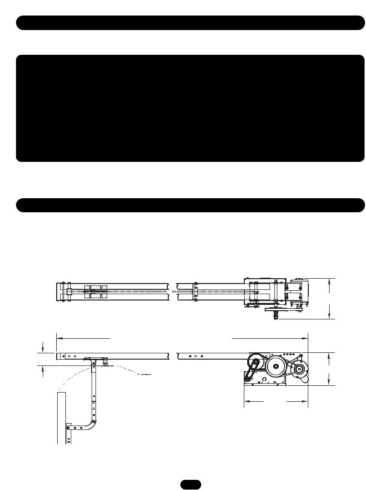
O P E R A T O R D I M E N S I O N S
WEIGHTS AND DIMENSIONS
HANGING WEIGHT: |
80-110 LBS. (36.3-50 kg) |
1313.05"-1/8”(33.15 cm)
*Door Height Plus 4 feet (minimum)
*Door Height Plus 4 feet (1.22 m) (minimum)
4" (10.2 cm)
4”
1110.63"-1/2”(29.54 cm)
Highest Pointt of Door Travel
*23*20.43"-1/2”
(59.51 cm)
3
O P E R A T O R S P E C I F I C A T I O N S
MECHANICAL
DRIVE REDUCTION: . . . . . . . .Primary: Heavy duty (5L) V-Belt. Secondary: #41 chain/sprocket.
Output: #48 chain
OUTPUT SHAFT SPEED: . . . . . . . . . . . . . . . . . . . . . . .96 R.P.M.
DOOR SPEED: . . . . . . . . . .7-8" per second depending on door BRAKE: . . . . . . . . . . . . . . . . . . . . .Solenoid actuated disc brake
BEARINGS: . . . . . . . . . . . .Output Shaft: Shielded Ball Bearing. Clutch Shaft: Iron Copper sintered and oil impregnated.
SAFETY
DISCONNECT: . . . . . . . . . . . . . . .Quick disconnect door arm for emergency manual door operation.
SAFETY PHOTO EYES (Optional CPS-L): Through beam or retro reflective devices used to provide non-contact safety protection.
SAFETY EDGE (Optional): Electric or pneumatic sensing device attached to the bottom edge of door.
4
P R E P A R A T I O N
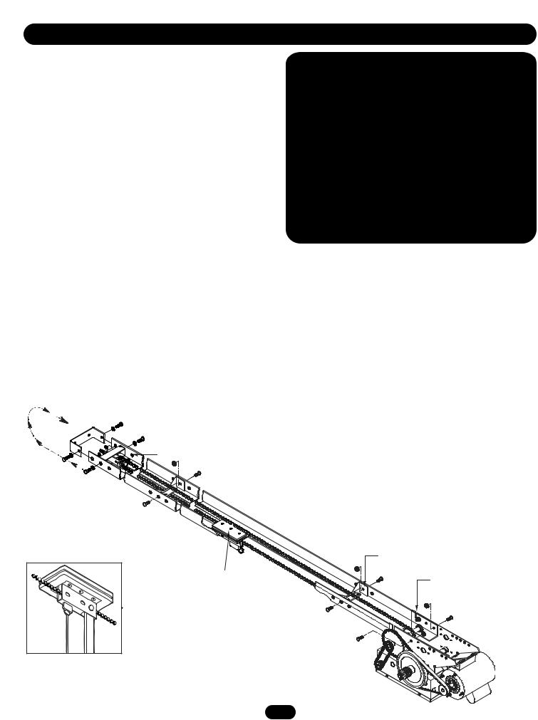
TRACK ASSEMBLY
1.Using the 3/8"-16 x 3/4" bolts and flange hex nuts provided, assemble the operator track by installing and tightening the track spacer brackets. Position the spacers evenly over the length of the track. NOTE: The nylon pad on the spacer bracket should face up.
2.Using (2) 3/8"-16 x 1" bolts and lock washers, install the front idler assembly to the second set of holes of one end of the track. Refer to the illustration below.
3.Slide the trolley carriage onto the track so that the hole of the door arm faces the front (towards door).
POWERHEAD ATTACHMENT
1.Position the track assembly on the frame of the powerhead so that the motor side of operator is in back (away from door ).
2.Using (2) 3/8"-16 x 3/4" bolts and flange hex nuts, install the front idler assembly to the second set of holes of one end of the track. Be sure the take-up bolt faces toward end of track. Refer to the illustration below.
3.Connect the track to the operator by fastening (2)
3/8"-16 x 3/4" bolts and nuts through the frame and the end holes in track. Tighten all four bolts to secure the track to the powerhead.

 WARNING
To prevent possible SERIOUS INJURY or DEATH:
•DO NOT connect electric power until instructed to do so.
•If the door lock needs to remain functional, install an interlock switch.
•ALWAYS call a trained professional door serviceman if door binds, sticks or is out of balance. An unbalanced door may not reverse when required.
•NEVER try to loosen, move or adjust doors, door springs, cables, pulleys, brackets or their hardware, ALL of which are under extreme tension and can cause SERIOUS PERSONAL INJURY.
•Disable ALL locks and remove ALL ropes connected to door BEFORE installing and operating door operator to avoid entanglement.
Reel Chain  Around Idler and over Spacer Brackets
Trolley Assembly
Front Idler Assembly
Spacer Bracket
(mounted nylon pad side up)
Trolley Carriage
L - Slot
I N S T A L L A T I O N
IMPORTANT NOTE: Before your operator is installed, be sure the door has been properly aligned and is working smoothly. The operator may be wall mounted or mounted on a bracket or shelf. If necessary, refer to the preparation on page 5. Refer to the illustrations and instructions below that suit your application.
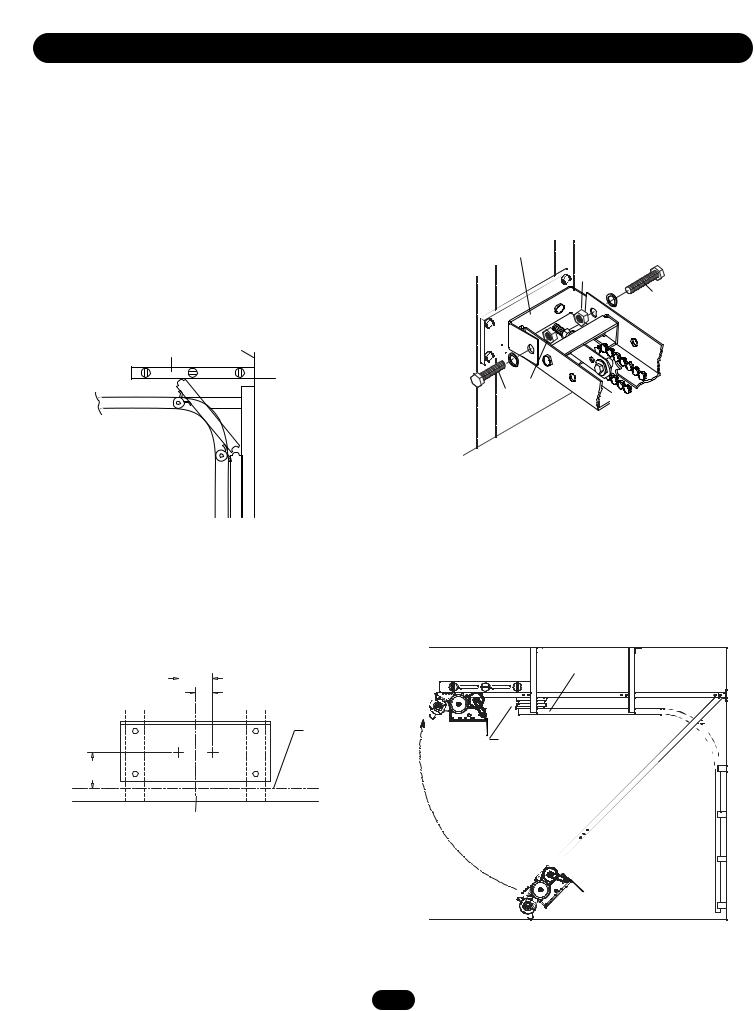
MOUNT THE HEADER BRACKET
1.Close the door and mark the inside vertical centerline of the door.
2.Extend the line onto the header wall above the door.
You can fasten the header bracket within 2' (.61 m) of the left or right of the door center only if a torsion spring or center bearing plate is in the way.
3.Open your door to the highest point of travel as shown. Draw an intersecting horizontal line on the header wall 4" (10.2 cm) above the high point. This height will provide travel clearance for the top edge of the door.
Carpenterʼs |
Header Wall |
Level |
|
High Point
of Travel
MOUNT THE OPERATOR
1.Position the operator on the floor below the header bracket.
2.Position the front idler assembly against the header bracket.
3.Align the bracket holes and join with hardware as shown.
Header Bracket 


 Nut
Nut
Bolt
Nut
 Bolt
Bolt
Door Travel
Projection
4.Using the projected lines for location, mount a suitable wood block or length of angle iron to the wall above the door opening. Refer to the illustration below. This will provide a mounting pad for the front header bracket of the operator. If necessary reinforce the wall with suitable mounting brackets to ensure adequate support of mounting pad. Using suitable hardware, mount the (U-shaped) front header bracket to the pad.
3.5" (8.9 cm)
1.75" (4.5 cm)
High Rise Point
Projection Line
4" Min. (10.2 cm)
4.Raise the operator to a horizontal position above the guide rails and temporarily secure with a suitable rope, chain, or support from the floor. Open door slowly, being careful not to dislodge the temporary support. Using the door as a support, place a level against the rail and shim the operator until it is horizontal. Make sure that the operator is aligned with the center line of the door.
Guide |
Rails |
Using the door as support, shim operator to a horizontal position.
Vertical Center Line of Door
Header Bracket Drill Pattern
Operator Alignment

I N S T A L L A T I O N
Top Roller
Mid-Span Support Brace
Powerhead Support Brace
7
I N S T A L L A T I O N
 WARNING
To reduce the risk of SEVERE INJURY or DEATH, ALWAYS install reversing sensors when the 3-button control station is out of sight of door or ANY other control (automatic or manual) is used. Reversing devices are recommended for ALL installations.
CLOSE OPEN
SAFETY
(Aux. Close) Limit Switch
OPEN Limit Switch
CLOSE Limit Switch
8
A D J U S T M E N T
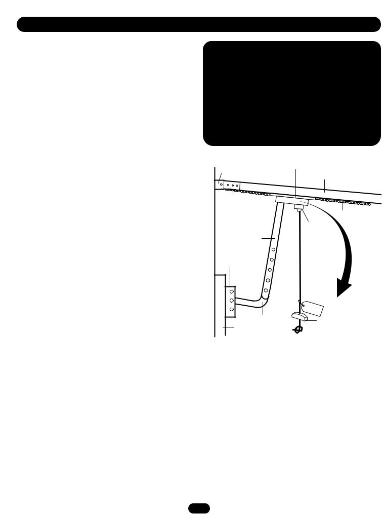
TO DISCONNECT DOOR FROM OPERATOR
The door should be in the fully closed position, if possible. Pull down on the emergency release handle and raise or lower the door manually.
TO RECONNECT DOOR ARM TO TROLLEY
The trolley will reconnect on the next UP or DOWN operation, either manually or by using the door control or remote.
To prevent possible SERIOUS INJURY or DEATH from a falling door or arm:
•DO NOT stand under the door arm when pulling the emergency release.
•If possible, use emergency release handle to disengage trolley ONLY when door is CLOSED. Weak or broken springs or unbalanced door could result in an open door falling rapidly and/or unexpectedly.
•NEVER use emergency release handle unless doorway is clear of persons and obstructions.
Header |
|
Bracket |
|
Straight |
|
Door Arm |
|
Assembly |
|
Door |
|
Bracket |
|
|
Curved |
Door |
Door Arm |
|
|
Trolley
NOTICE
Track
Chain
Emergency
Disconnect
Emergency
Release
Handle
9
A D J U S T M E N T
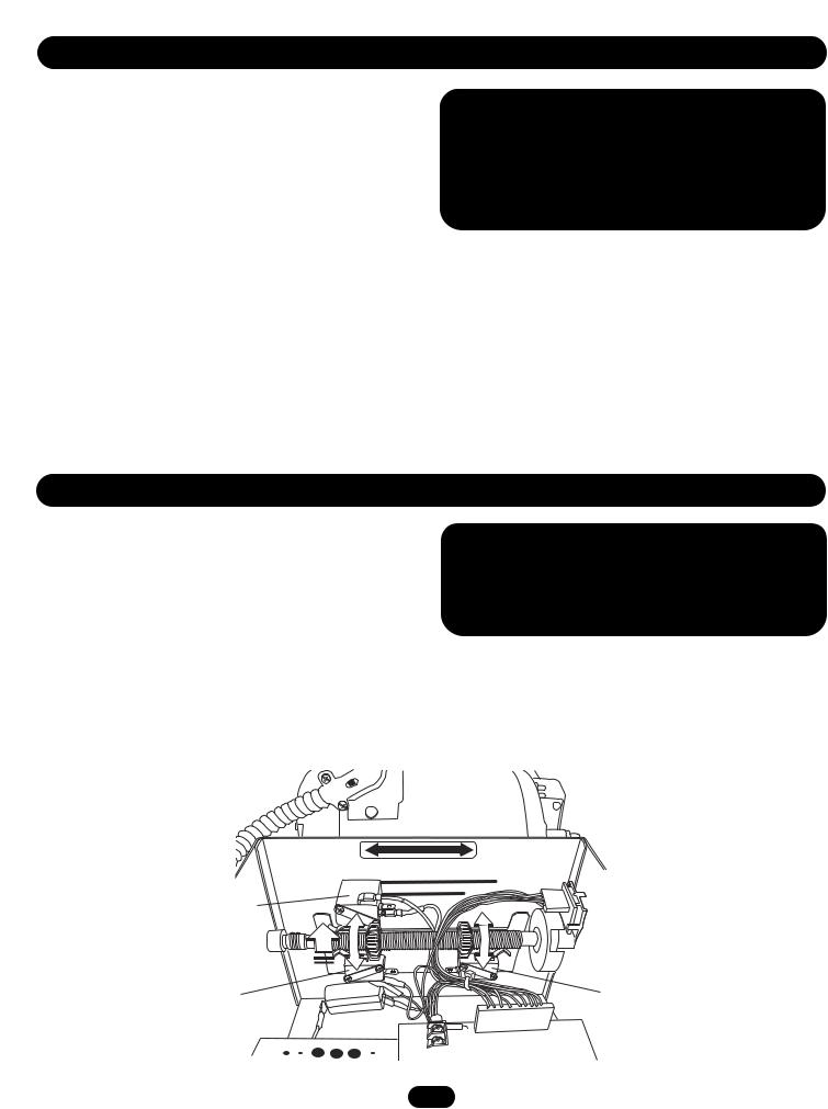
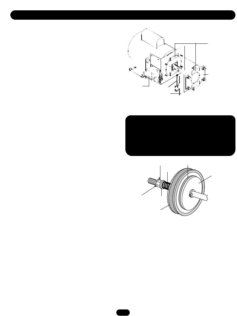
BRAKE ADJUSTMENT
The solenoid brake is adjusted at the factory and should not need additional adjustment for the life of the brake assembly.
Replace brake assembly when necessary. Refer to the illustration for identification of components for the solenoid type brake system.
CLUTCH ADJUSTMENT AND AUXILIARY REVERSAL SYSTEM
The Auxiliary Reversal System is designed to protect the door and motorized operator. It is NOT a substitute for a safety sensing device. The Auxiliary Reversal System works in tandem with the adjustable clutch to detect if a closing door runs into or comes across an obstruction. If an obstruction is met and causes the clutch to slip, the Auxiliary Reversal System will return the door to the full open position when closing or stops the door when opening.
1.Remove cotterpin from nut on the clutch shaft.
2.Back off clutch nut until there is very little tension on the clutch spring.
3.Tighten clutch nut gradually until there is just enough tension to permit the operator to move the door smoothly but to allow the clutch to slip if the door is obstructed. When the clutch is properly adjusted, it should generally be possible to stop the door by hand during travel.
4.Reinstall cotterpin.
 WARNING
To prevent possible SERIOUS INJURY or DEATH, install reversing sensors when the 3-button control station is out of sight of the door or ANY other control (automatic or manual) is used. Reversing devices are recommended for ALL installations.
Adjusting Nut |
Clutch Pad |
Spring |
|
Clutch Plate
Cotterpin Washer
Clutch Pulley
10
P O W E R W I R I N G & G R O U N D W I R I N G

 WARNING
To reduce the risk of SEVERE INJURY or DEATH:
•ANY maintenance to the operator or in the area near the operator MUST NOT be performed until disconnecting the electrical power and locking-out the power via the operator power switch. Upon completion of maintenance the area MUST be cleared and secured, at that time the unit may be returned to service.
•Disconnect power at the fuse box BEFORE proceeding. Operator MUST be properly grounded and connected in accordance with local electrical codes. The operator should be on a separate fused line of adequate capacity.
•ALL electrical connections MUST be made by a qualified individual.
•DO NOT install ANY wiring or attempt to run the operator without consulting the wiring diagram. We recommend that you install an optional reversing edge BEFORE proceeding with the control station installation.
•ALL power wiring should be on a dedicated circuit and well protected. The location of the power disconnect should be visible and clearly labeled.
•ALL power and control wiring MUST be run in separate conduit.
Single Phase Power Wiring
Line Power
115/230 Vac
Single Phase
GROUND WIRING CONNECTIONS
1.Connect earth ground to the chassis ground screw in the electrical box enclosure.
2.Use same conduit entry into the electrical box as the power wiring.
IMPORTANT NOTE: This unit must be properly grounded. Failure to properly ground this unit could result in electric shock and serious injury.
Hot
Neutral
Gnd
 Loading...