


 Loading...
The Chamberlain Group, Inc.
845 Larch Avenue
Elmhurst, Illinois 60126-1196
www.liftmaster.com
Model 8500
GARAGE DOOR OPENER
For Residential and Light Duty Commercial Use Install On Sectional Doors With Torsion Assemblies Only
S e e Pa
g
e
18
|
|
|
|
t |
|
|
|
e |
|
|
|
D |
|
|
|
r |
|
|
|
o |
|
|
|
|
f |
|
|
|
|
|
s |
l |
|
i |
|
This product is intended for installation only by trained garage door technicians. This product may require adjustments to door springs and or track configurations. This product is not intended for use on low headroom tracks or garage doors utilizing extension springs.
■Please read this manual and the enclosed safety materials carefully!
■Fasten the manual near the garage door after installation.
■The door WILL NOT CLOSE unless the Protector System® and cable tension monitor are connected and properly aligned.
■Periodic checks of the garage door opener are required to ensure safe operation.
■The model number label is located behind the hinged door of your opener.
■DO NOT exceed 10 complete cycles of door operation per hour.
■This garage door opener is ONLY compatible with MyQ™ and Security 2.0™ accessories.

Table of Contents
INTRODUCTION |
2 |
Install the Protector System® ................ |
13 |
|
Safety Symbol and Signal Word Review .. |
2 |
Connect Power....................................... |
16 |
|
Planning................................................... |
3 |
Install the Battery Backup (optional) ...... |
18 |
|
Preparing Your Garage Door.................... |
4 |
ADJUSTMENT |
19 |
|
Tools Needed ........................................... |
4 |
Program the Travel Limits...................... |
19 |
|
Carton Inventory ...................................... |
5 |
Set the Force .......................................... |
20 |
|
Hardware ................................................. |
5 |
Test the Safety Reversal System ............ |
21 |
|
ASSEMBLY |
6 |
Test the Protector System® ................... |
21 |
|
Attach the Collar to the |
6 |
Test Cable Tension Monitor ................... |
22 |
|
Garage Door Opener ................................ |
Test Power Door Lock |
22 |
||
Attach Mounting Bracket to |
|
|||
|
To Open the Door Manually |
22 |
||
Garage Door Opener |
7 |
|||
|
|
|||
INSTALLATION |
7 |
OPERATION |
23 |
|
Position and Mount the |
|
Using Your Garage Door Opener............ |
23 |
|
Garage Door Opener ................................ |
8 |
Using the Door Control |
|
|
Attach the Emergency Release Rope |
|
(MyQ® Control Panel) ............................ |
24 |
|
and Handle ............................................... |
9 |
Using the Remote Control...................... |
25 |
To Erase All Codes From the |
|
Door Control (MyQ® Control Panel) |
|
Memory ................................................. |
27 |
Reprogramming Light or |
|
Additional Light...................................... |
28 |
Additional Programming for the Keyless |
|
Entry (Not Provided) .............................. |
28 |
MAINTENANCE |
29 |
Care of Your Garage Door Opener.......... |
29 |
TROUBLESHOOTING |
30 |
Diagnostic Chart .................................... |
30 |
Troubleshooting..................................... |
31 |
Troubleshooting (Continued) ................. |
32 |
REPAIR PARTS |
33 |
Installation Parts .................................... |
33 |
Garage Door Opener Assembly Parts..... |
34 |
ACCESSORIES |
35 |
Install Power Door Lock........................... |
9 |
Attach the Cable Tension Monitor |
|
(Required).............................................. |
10 |
Install the Door Control |
|
(MyQ® Control Panel) ............................ |
11 |
Install Remote Light............................... |
12 |
PROGRAMMING |
26 |
REPAIR PARTS AND SERVICE |
36 |
|
WARRANTY |
36 |
|||
To Add a Remote Control, |
|
|||
Keyless Entry, or MyQ® Enabled |
|
|
|
|
Accessories using the |
|
|
|
Door Control (MyQ® Control Panel) ....... 26
Internet Gateway (Not Provided)............ 27
Introduction
Safety Symbol and Signal Word Review
This garage door opener has been designed and tested to offer safe service provided it is installed, operated, maintained and tested in strict accordance with the instructions and warnings contained in this manual.
When you see these Safety Symbols and Signal Words on the following pages, they will alert you to the possibility of serious injury or death if you do not comply with the warnings that accompany them. The hazard may come from something mechanical or from electric shock. Read the warnings carefully.
When you see this Signal Word on the following pages, it will alert you to the possibility of damage to your garage door and/or the garage door opener if you do not comply with the cautionary statements that accompany it. Read them carefully.
Mechanical
Electrical
2
Introduction
Planning
Survey your garage area to see if any of the conditions below apply to your installation. Depending on your requirements, additional materials may be required.
THIS GARAGE DOOR OPENER IS COMPATIBLE WITH:
•Doors that use a torsion bar and springs. The torsion bar must be 1 inch (2.5 cm) diameter.
•4-6 inch (10-15 cm) drums, not to be used on tapered drums over 6 inches (15 cm).
•High lift (up to 54 inches (137.2 cm) high) and standard lift sectional doors up to 14 feet (4.2 m) high.
NOTE: Inspect the torsion bar while the door is raised and lowered. It is important that there is no noticeable movement up and down or left and right. If the movement is not corrected, the life of the garage door opener will be greatly reduced.
•Doors up to 18 feet (5.4 m) wide.
•Doors up to 180 sq. ft. (16.7 sq. m).
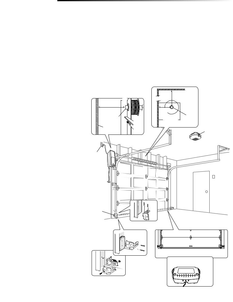
Review or inspect proposed installation area. The garage door opener can be installed on the left or right side of door. Select the side that meets the requirements listed below.
a. |
Must have minimum of 2-1/2 inches |
|
|
|
b 3 inches |
|
(6.4 cm) between the garage wall and |
c |
|
|
|
|
the center of the torsion bar. |
8 inches |
d |
(7.6 cm) |
|
|
|
||||
|
|
|
(20.3 cm) |
|
|
b. |
Must have minimum of 3 inches |
|
a |
|
|
(7.6 cm) between the ceiling and the |
|
Torsion |
|
|
center of torsion bar. |
Torsion bar |
2-1/2 inches |
|
|
(6.4 cm) |
bar |
||
c. |
Must have minimum of 8 inches |
Wall or |
|
|
|
(20.3 cm) between the side garage |
|
|
|
|
obstruction |
|
Remote light |
|
|
wall (or obstruction) and the end of |
|
|
|
|
|
|
|
|
|
torsion bar. |
|
|
|
d. The torsion bar must extend at least 1-5 inches (2.5-12 cm) past the
bearing plate. This may vary depending e on your installation requirements.
e. An electric outlet is required within
6 feet (1.8 m) of the installation area. If outlet does not exist, contact a qualified electrician.
f. |
Depending upon garage construction, |
|
|
|
extension brackets or wood blocks |
|
|
|
may be needed to install safety |
|
|
|
reversing sensors. |
g |
|
g. |
Alternate floor mounting of the |
||
Safety reversing |
|||
|
safety reversing sensors will require |
sensor |
|
|
|
||
|
hardware (not provided). |
|
h.Any gap between the floor and the
|
bottom of the door must not exceed |
f |
|
|
1/4 inch (6 mm), otherwise the |
|
|
|
safety reversal system may not work |
|
|
|
h |
|
|
|
properly. |
|
|
i. |
A model 475LM Battery Backup is |
|
|
|
strongly recommended if there is |
|
|
|
no access door to the garage, as |
i |
475LM Battery Backup |
|
this garage door opener cannot be |
|
|
|
used in conjunction with an external |
|
|
|
emergency release mechanism. |
|
|
3
Introduction
Preparing Your Garage Door
BEFORE YOU BEGIN:
•Disable locks.
•Remove any ropes connected to the garage door.
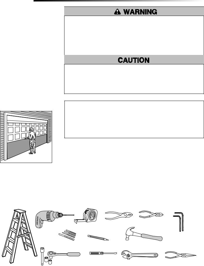
Complete the following test to make sure the garage door is balanced and is not sticking or binding:
1.Lift the door halfway up. Release the door. If balanced, it should stay in place, supported entirely by its springs.
2.Raise and lower the door to check for binding or sticking.
If your door binds, sticks, or is out of balance, call a trained door systems technician.
3.Verify equal cable tension on each side of door. Cable tension should remain equal during the entire travel of the door.
Sectional Door
To prevent possible SERIOUS INJURY or DEATH:
•ALWAYS call a trained door systems technician if garage door binds, sticks, or is out of balance. An unbalanced garage door may NOT reverse when required.
•NEVER try to loosen, move or adjust garage door, door springs, cables, pulleys, brackets or their hardware, ALL of which are under EXTREME tension.
•Disable ALL locks and remove ALL ropes connected to garage door BEFORE installing and operating garage door opener to avoid entanglement.
To prevent damage to garage door and opener:
•ALWAYS disable locks BEFORE installing and operating the opener.
•ONLY operate garage door opener at 120 V, 60 Hz to avoid malfunction and damage.
•DO NOT exceed 10 complete cycles of door operation per hour.
Specifications
Volts . . . . . . . . . . . . . . . . . . . . . . . . . . . . . . . . . . . . . . . . . . . 120 Vac - 60 Hz, ONLY
Current . . . . . . . . . . . . . . . . . . . . . . . . . . . . . . . . . . . . . . . . . . . . . . . . . . . . 1.0 AMP
Rated Load . . . . . . . . . . . . . . . . . . . . . . . . . . . . . . . . . . . . . . . . . . . . . .325 in. lb/sec 10 Cycles per Hour
Tools Needed
During assembly, installation and adjustment of the garage door opener, instructions will call for hand tools as illustrated below.
|
1 |
2 |
|
|
Drill |
Tape Measure |
|
|
5/32", 3/16", 5/16" |
|
Pencil |
|
and 3/4" Drill Bits |
|
|
Stepladder |
1/4", 5/16" & 3/8" Sockets |
Screwdriver |
|
|
|||
and Wrench with 6" Extension
Pliers |
Wire Cutters |
3/16" and 1/8" Hex Key Wrench
Claw Hammer
Adjustable End Wrench |
Needle Nose Pliers |
Torque Meter (not shown)
4
Introduction
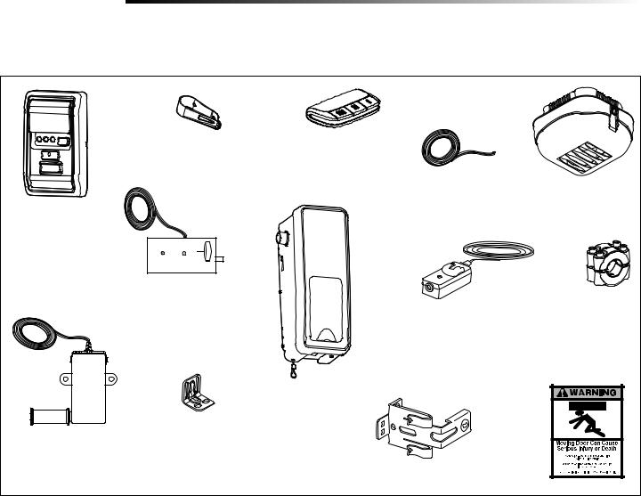
Carton Inventory
Accessories included with the garage door opener will vary depending on the model purchased. If anything is missing, carefully check the packing material.
 HOLD
HOLD
OPEN
LIGHT
Door Control
(MyQ® Control Panel)
Model 888LM
Cable Tension Monitor with 2-Conductor Green/White Bell Wires
Remote Control |
3-Button Premium Remote Control |
Visor Clip |
Model 895MAX (1) |
Power Door Lock with 2-Conductor White & White/Black Bell Wire with Connector
Garage Door Opener
Mounting Bracket
2 Conductor Bell Wire
White & White/Red
The Protector System®
(2) Safety Reversing Sensors (1 Sending Eye and 1 Receiving Eye) with 2-Conductor White & White/Black Bell Wire attached
Safety Reversing Sensor Bracket (2)
Remote Light
(Garage Door Opener Light) with Hardware Bag
Collar with Screws
Safety Labels
and Literature
Hardware
Hex Screw #14-10x1-7/8" (4)
Screw #6x1-1/4" (2) Machine Screw #6x1" (2)
Carriage Bolt 1/4"-20x1/2" (2)
Wing Nut 1/4"-20 (2)
Pan Head Screw 1/4"-20x1/2" (2) Hex Head Screw #8x1" (2)
Self Tapping Screw #10-32 (2)
Drywall Anchor (2)
Wall Anchor (Screw-In) (2)
Handle
Rope
Insulated Staples
Lock Template
5

Assembly
1 Attach the Collar to the Garage Door Opener
To avoid installation difficulties, do not run the garage door garage door opener until instructed to do so.
The garage door opener can be installed on either side of the door (see PLANNING section page 3). The illustrations shown are for installation on the left side.
1.Loosen the collar screws.
2.Attach collar to the garage door opener motor shaft. The side of the collar with the larger hole should be placed on the motor shaft. Ensure that the collar is seated all the way on motor shaft until stop is reached.
3.Position the collar so the screws are facing out and are accessible when attached to the torsion bar.
4.Tighten the screws on both sides of the collar equally to secure collar to the motor shaft (to 12-14 ft./lbs. of torque).
NOTE: Do not tighten set screws until indicated.
To prevent possible SERIOUS INJURY or DEATH, the collar MUST be properly tightened. The door may NOT reverse correctly or limits may be lost due to collar slip.
Collar
Motor Shaft
Collar Screws
Set Screws
3/16 Hex
Key Wrench
RIGHT |
WRONG |
6
Assembly
2 Attach Mounting Bracket to Garage Door Opener
1.Loosely attach slotted side of mounting bracket to the same side of the garage door opener as the collar, using self-threading screws provided.
NOTE: Do not tighten screws until instructed.
Socket Wrench
HARDWARE
Screw #10-32 (2)
Installation
IMPORTANT INSTALLATION INSTRUCTIONS

 WARNING
To reduce the risk of SEVERE INJURY or DEATH:
1.READ AND FOLLOW ALL INSTALLATION WARNINGS AND INSTRUCTIONS.
2.Install door operator ONLY on properly balanced and lubricated door. An improperly balanced door may NOT reverse when required and could result in SEVERE INJURY or DEATH.
3.ALL repairs to cables, spring assemblies and other hardware MUST be made by a trained door systems technician BEFORE installing garage door opener.
4.Disable ALL locks and remove ALL ropes connected to door BEFORE installing garage door opener to avoid entanglement.
5Mount the emergency release within reach, but at least 6 feet (1.83 m) above the floor and avoiding contact with vehicles to avoid accidental release.
6.NEVER connect door operator to power source until instructed to do so.
7.NEVER wear watches, rings or loose clothing while installing or servicing the garage door opener. They could be caught in door or operator mechanisms.
8.Install wall-mounted door control:
•within sight of the door.
•out of reach of children at minimum height of 5 feet (1.5 m).
•away from ALL moving parts of the door.
9.Install the Entrapment Warning Placard next to the door control in a prominent location.
10.Place manual release/safety reverse test label in plain view on inside of door.
11.Upon completion of installation, test safety reversal system.
7
Installation
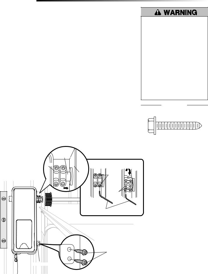
1 Position and Mount the Garage Door Opener
NOTE: For additional mounting options refer to the accessories page.
1.Close the garage door completely.
2.Slide the garage door opener onto the end of the torsion bar. If the torsion bar is too long or damaged, you may need to cut the torsion bar. Ensure the collar does not touch the bearing plate.
3.Use a level to position and vertically align the garage door opener. Verify the mounting bracket is located on a solid surface such as wood, concrete or door/flag bracket.
4.When the garage door opener is properly aligned, mark the mounting bracket holes. If necessary, tighten collar screws on the torsion bar to hold garage door opener in place while marking holes.
NOTE: The garage door opener does not have to be flush to wall.
5.Remove the garage door opener from torsion bar. Drill 3/16 inch pilot holes at the marked locations. Drill through steel plate if necessary.
6.Slide the garage door opener back onto the torsion bar until pilot holes align with bracket. Securely tighten collar screws to the torsion bar to 12-14 ft./lbs. of torque (Figure 1).
7.Securely tighten both set screws (Figure 1).
NOTE: You may need to manually raise the door slightly in order to reach the set screws.
8.Secure the mounting bracket to the wall and to the garage door opener. Use the 14-10x1-7/8 inch screws to secure the mounting bracket to the wall.
9.Secure the antenna wire with a staple to prevent antenna from being entangled in a door roller.
To prevent possible SERIOUS INJURY or DEATH:
•Concrete anchors MUST be used if mounting bracket into masonry.
•NEVER try to loosen, move or adjust garage door, springs, cables, pulleys, brackets or their hardware, ALL of which are under EXTREME tension.
•ALWAYS call a trained door systems technician if garage door binds, sticks or is out of balance. An unbalanced garage door might NOT reverse when required.
•Operator MUST be mounted at a right angle to the torsion bar to avoid premature wear on the collar.
HARDWARE
14-10x1-7/8" Hex Screws (2) |
Insulated Staples |
|
(Not shown) |
||
|
|
Torsion Bar |
|
Collar |
|
FIGURE 1 |
|
Bearing |
Collar |
|
Plate |
|
|
Screws |
|
|
|
|
|
|
Set Screws |
3/16" Hex Key Wrench
Screws 14-10x1-7/8"
Mounting Bracket
8

Installation
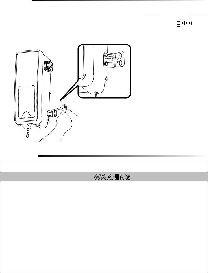
2 Attach the Emergency Release Rope and Handle
1.Thread one end of the rope through the hole in the top of the red handle so “NOTICE” reads right side up as shown. Secure with an overhand knot at least 1 inch (2.5 cm) from the end of the rope to prevent slipping.
2.Thread the other end of the rope through the loop in the emergency release cable. Adjust rope length so the handle is no higher than 6 feet (1.83 m) above the floor. Secure with an overhand knot.
NOTE: If it is necessary to cut the rope, heat seal the cut end with a match or lighter to prevent unraveling.
Garage Door Opener
Emergency
Release Cable
Overhand |
Knot |
Emergency |
Release Handle |
Overhand
Knot
3 Install Power Door Lock
The power door lock is used to prevent the garage door from being manually opened once the door is fully closed.
1.The power door lock must be mounted within 10 feet (3.01 m) of garage door opener with approximately a 3 inch (7.6 cm) distance between the center of a door roller and the hole for the power door lock bolt. If possible, mount on same side as garage door opener. The second roller from the bottom is ideal for most installations.
2.Ensure rail surface is clean and attach lock template to track.
3.Drill holes as marked on the template.
4.Fasten power door lock to the outside of the garage door track with hardware provided.
5.Run bell wire up wall to garage door opener. Use insulated staples to secure wire in several places. Insert wire through the bottom of the garage door opener.
6.Plug the connector into the garage door opener.
Connector
 Bell Wire
10 feet (3.01 m) max.
Garage Door
Track
To prevent possible SERIOUS INJURY or DEATH from a falling garage door:
•If possible, use emergency release handle to disengage door ONLY when garage door is CLOSED. Weak or broken springs or unbalanced door could result in an open door falling rapidly and/or unexpectedly.
•NEVER use emergency release handle unless garage doorway is clear of persons and obstructions.
HARDWARE
Handle
Rope
HARDWARE
Lock Screws
1/4"-20x1/2" (2) 


 Insulated Staples
(Not shown)
Lock Template
Door Lock
Roller
Approx. 3" (7.6 cm)
9
Installation
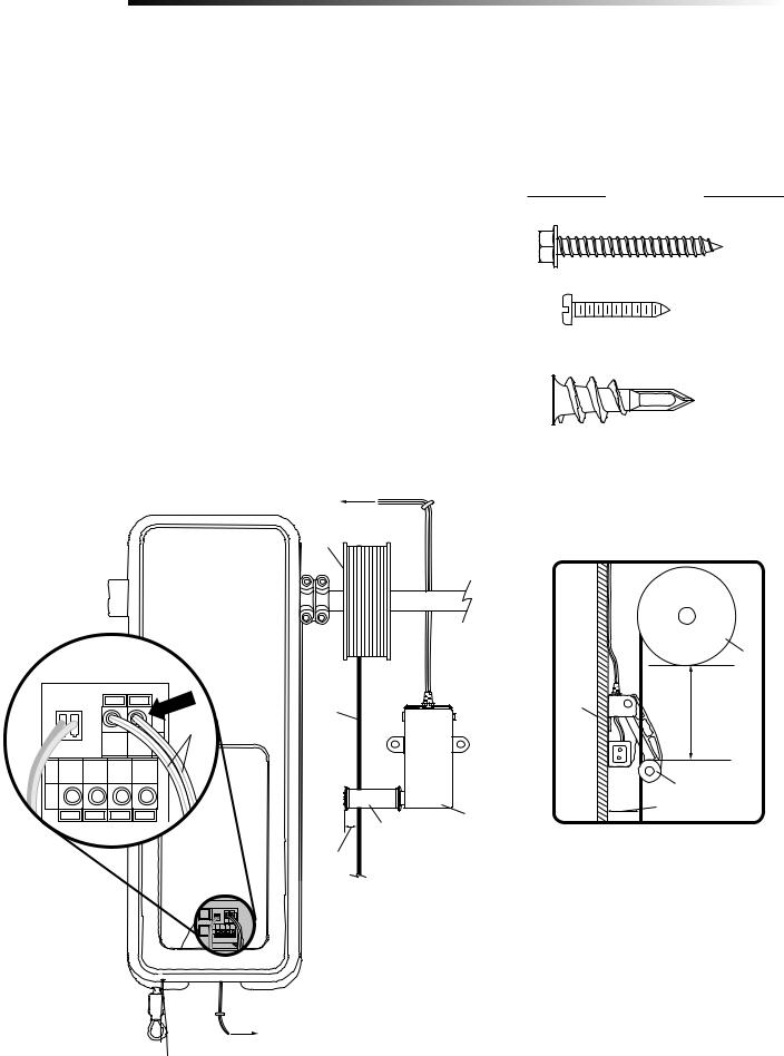
4 Attach the Cable Tension Monitor (Required)
NOTE: The cable tension monitor is shipped for left side installation. It is recommended that the cable tension monitor be installed on the same side of the door as the garage door opener. For right side installation, remove the snap-ring holding the roller in place and reassemble it on the opposite side of the cable
tension monitor.
1.Position the cable tension monitor as close to the drum as possible. Make sure cable tension monitor is located over a wood support member and the roller is free from any obstructions.
NOTE: There must be no obstructions in the installation area that prevent the cable tension monitor or the cable itself from closing completely when slack is detected.
2.Mark and drill 3/16 inch pilot holes for screws (pilot holes are not required for anchors).
NOTE: If the cable tension monitor cannot be mounted into wood with the lag screws provided, it can be mounted into 1/2 inch or greater drywall using the wall anchors (2) and the #8 hex screws (2) provided in the hardware bag.
3.Attach the cable tension monitor to the wall using the hardware provided. Make sure that the roller is on top of the cable.
4.Run bell wire to garage door opener. Use insulated staples to secure wire.
5.Connect bell wire to the green quick-connect terminals on the garage door opener (polarity is not important).
NOTE: Cable must have tension through entire door travel. Make sure there is no slack in cable on opposite side of garage door during normal operation. If slack occurs during door travel, adjust cables as required.
(to garage door opener)
The cable tension monitor MUST be connected and properly installed before the garage door opener will move in the down direction.
The cable tension monitor detects ANY slack that may occur in the cables and will reverse the door, eliminating service calls.
HARDWARE
#8Hex HeadScrew(2)(2)
Insulated Staples
(Not shown)
Screw #6 (2)
Wall Anchor (2)
To insert or release wire, push in tab with screwdriver tip
WHT/GRN |
Drum |
|
SIDE VIEW |
|
|
|
|
|
Drum |
Cable |
Wall |
2"-6" |
|
|
(5-15 cm) |
|
|
Cable Tension |
|
|
Monitor Roller |
|
Cable Tension |
3/4" Min.(18 cm Min.) |
|
|
|
Cable Tension |
Monitor |
|
Monitor Roller |
|
|
1/8"-1/4" |
|
|
(3-6 cm) |
|
|
(to cable tension monitor)
10
Installation
5 Install the Door Control (MyQ® Control Panel)
Install the door control within sight of the door at a minimum height of 5 feet (1.5 m) where small children cannot reach, and away from the moving parts of the door.
For gang box installations it is not necessary to drill holes or install the drywall anchors. Use the existing holes in the gang box.
NOTE: Due to power consumption this door control (Model 888LM) cannot be used in conjunction with another wired door control connected to your garage door opener. If an additional door control is needed, the wireless door control model 885LM can be programmed to the door control (Model 888LM).
1.Strip 7/16" (11 mm) of insulation from one end of the wire and separate the wires.
2.Connect wires to the door control. Make sure the polarity is correct.
•Red wire to the RED terminal.
•White wire to the WHT terminal.
3.Mark the location of the bottom mounting hole and drill a 5/32" (4 mm) hole.
4.Install the bottom screw, allowing 1/8" (3 mm) to protrude from the wall.
5.Position the bottom hole of the door control over the screw and slide down into place.
6.Lift the push bar up and mark the top hole.
7.Remove the door control from the wall and drill a 5/32" (4 mm) hole for the top screw.
8.Position the bottom hole of the door control over the screw and slide down into place. Attach the top screw.
9.Run the white and red/white wire from the door control to the garage door opener. Attach the wire to the wall and ceiling with the staples (not applicable for gang box or pre-wired installations). Do not pierce the wire with the staple as this may cause a short or an open circuit.
10.Strip 7/16" (11 mm) of insulation from the end of the wire near the garage door opener. Connect bell wire to the quick-connect terminals on the garage door opener: white to white and white/red to red.
11.Fasten the warning placard to the wall next to the door control.
NOTE: DO NOT connect the power and operate the garage door opener at this time. The door will travel to the full open position but will not return to the close position until the sensor beams are connected and properly aligned. See page 13.
(to garage door opener)
7/16" (11 mm)
(to door control)
11
To prevent possible SERIOUS INJURY or DEATH from electrocution:
•Be sure power is NOT connected BEFORE installing door control.
•Connect ONLY to 7-28 VOLT low voltage wires.
To prevent possible SERIOUS INJURY or DEATH from a closing garage door:
•Install door control within sight of garage door, out of reach of children at a minimum height of 5 feet (1.5 m), and away from ALL moving parts of door.
•NEVER permit children to operate or play with door control push buttons or remote control transmitters.
•Activate door ONLY when it can be seen clearly, is properly adjusted, and there are no obstructions to door travel.
•ALWAYS keep garage door in sight until completely closed. NEVER permit anyone to cross path of closing garage door.
HARDWARE
Insulated Staples (Not shown)
Screw 6ABx-1-1/4" (Standard installation) (2)
Screw 6-32x1" (pre-wired) (2) |
Drywall Anchors (2) |
To insert or release wire, push in tab with screwdriver tip
WHT
Red White
WHT/RED
Loading...