


MT5011E
Table of contents
 Loading...
Serial #
(located on electrical box)
Installation Date
2 YEAR WARRANTY
NOT FOR RESIDENTIAL USE
I N S T A L L A T I O N M A N U A L
I N S T A L L A T I O N M A N U A L
MODEL MT5011E/BMT5011E
MEDIUM DUTY DOOR OPERATOR
Now with
Built in
Radio Receiver
Radio Receiver
Built on Board
315MHz
INTENDED FOR PROFESSIONAL
INTENDED FOR PROFESSIONAL
INSTALLATION ONLY
INSTALLATION ONLY
A SAFETY DEVICE IS HIGHLY RECOMMENDED.
Visit www.LiftMaster.com to locate a professional installing dealer in your area.

2
SAFETY INFORMATION
Mechanical
WARNINGWARNING
WARNING
WARNING
WARNINGWARNING
WARNING
CAUTIONCAUTION
WARNING
WARNING
IMPORTANT NOTES:
• BEFORE attempting to install, operate or maintain the operator,
you must read and fully understand this manual and follow all
safety instructions.
• DO NOT attempt repair or service of your commercial door and
gate operator unless you are an Authorized Service Technician.
When you see this Signal Word on the following pages, it will
alert you to the possibility of damage to your door and/or the
door operator if you do not comply with the cautionary
statements that accompany it. Read them carefully.
Electrical
When you see these Safety Symbols and Signal Words on the
following pages, they will alert you to the possibility of serious
injury or death if you do not comply with the warnings that
accompany them. The hazard may come from something
mechanical or from electric shock. Read the warnings carefully.
SAFETY INFORMATION . . . . . . . . . . . . . . . . . . . . . . . . . . . . . . . . . . . . . . . . . . . . . . . . . . . . . . . . . . . . . . . . . . . . . . . . . .2
APPLICATION . . . . . . . . . . . . . . . . . . . . . . . . . . . . . . . . . . . . . . . . . . . . . . . . . . . . . . . . . . . . . . . . . . . . . . . . . . . . . . . . . 3
OPERATOR DIMENSIONS . . . . . . . . . . . . . . . . . . . . . . . . . . . . . . . . . . . . . . . . . . . . . . . . . . . . . . . . . . . . . . . . . . . . . . . .4
OPERATOR SPECIFICATIONS . . . . . . . . . . . . . . . . . . . . . . . . . . . . . . . . . . . . . . . . . . . . . . . . . . . . . . . . . . . . . . . . . . . .4
CARTON INVENTORY. . . . . . . . . . . . . . . . . . . . . . . . . . . . . . . . . . . . . . . . . . . . . . . . . . . . . . . . . . . . . . . . . . . . . . . . . . . 5
PREPARATION . . . . . . . . . . . . . . . . . . . . . . . . . . . . . . . . . . . . . . . . . . . . . . . . . . . . . . . . . . . . . . . . . . . . . . . . . . . . . . . . 5
ASSEMBLY . . . . . . . . . . . . . . . . . . . . . . . . . . . . . . . . . . . . . . . . . . . . . . . . . . . . . . . . . . . . . . . . . . . . . . . . . . . . . . . . . 6-8
TYPICAL INSTALLATION . . . . . . . . . . . . . . . . . . . . . . . . . . . . . . . . . . . . . . . . . . . . . . . . . . . . . . . . . . . . . . . . . . . . . .9-14
ADJUSTMENT . . . . . . . . . . . . . . . . . . . . . . . . . . . . . . . . . . . . . . . . . . . . . . . . . . . . . . . . . . . . . . . . . . . . . . . . . . . . . .14-15
OPTIONAL SAFETY DEVICE CONFIGURATIONS . . . . . . . . . . . . . . . . . . . . . . . . . . . . . . . . . . . . . . . . . . . . . . . . . .15-16
LOGIC BOARD LAYOUT . . . . . . . . . . . . . . . . . . . . . . . . . . . . . . . . . . . . . . . . . . . . . . . . . . . . . . . . . . . . . . . . . . . . . . . . . 17
BASIC PROGRAMMING . . . . . . . . . . . . . . . . . . . . . . . . . . . . . . . . . . . . . . . . . . . . . . . . . . . . . . . . . . . . . . . . . . . . 18-20
TESTING . . . . . . . . . . . . . . . . . . . . . . . . . . . . . . . . . . . . . . . . . . . . . . . . . . . . . . . . . . . . . . . . . . . . . . . . . . . . . . . . . . . . .21
MANUAL DISCONNECT . . . . . . . . . . . . . . . . . . . . . . . . . . . . . . . . . . . . . . . . . . . . . . . . . . . . . . . . . . . . . . . . . . . . . . . . .21
TROUBLESHOOTING . . . . . . . . . . . . . . . . . . . . . . . . . . . . . . . . . . . . . . . . . . . . . . . . . . . . . . . . . . . . . . . . . . . . . . . 22-23
DIAGRAM . . . . . . . . . . . . . . . . . . . . . . . . . . . . . . . . . . . . . . . . . . . . . . . . . . . . . . . . . . . . . . . . . . . . . . . . . . . . . . . . . . . 23
REPAIR PARTS . . . . . . . . . . . . . . . . . . . . . . . . . . . . . . . . . . . . . . . . . . . . . . . . . . . . . . . . . . . . . . . . . . . . . . . . . . . . 24-26
ACCESSORIES . . . . . . . . . . . . . . . . . . . . . . . . . . . . . . . . . . . . . . . . . . . . . . . . . . . . . . . . . . . . . . . . . . . . . . . . . . . . . . . .27
CONTROL CONNECTIONS . . . . . . . . . . . . . . . . . . . . . . . . . . . . . . . . . . . . . . . . . . . . . . . . . . . . . . . . . . . . . BACK COVER
TABLE OF CONTENTS
3
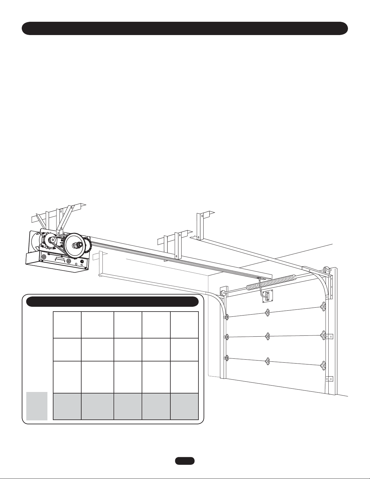
APPLICATION
MAXIMUM DOOR AREA AND MAXIMUM DOOR HEIGHT 14'
STANDARD SECTIONAL
SQUARE
FEET
---
24 ga.
22 ga.
Steel
20 ga.
Steel
16 ga.
Steel
---
Fiberglass
Aluminum
Doors
Wood
Doors
--- ---
--- ---
24 ga.
Steel
Insulated
20 ga.
Steel
Insulated
16 ga.
Steel
Insulated
310 260 225 150 100
NOTE: Actual track length will exceed door height by 2'.
INTRODUCTION
This Medium Duty Commercial Door Operator includes a number of features that will provide years of reliable and safe operation.
Features:
• Supports both monitored and non-monitored safety devices: Safety devices detect obstructions in the door's path and
automatically reverse a closing door. Safety devices are highly recommended by the manufacturer.
• Radio receiver: A factory installed radio receiver allows remote controls, keyless entries and other remote command devices to be
programmed to the operator.
• Timer To Close: The Timer To Close feature allows the door to automatically close after a preset time (only available with B2
wiring and a monitored safety device).
• Wiring Types: The functionality of the operator is based on the wiring type. The operator is shipped from the factory in standard
C2 wiring type (factory default). Some wiring types will require an optional safety device. Refer to Basic Programming Section for
descriptions of wiring types, requirements and programming.
4
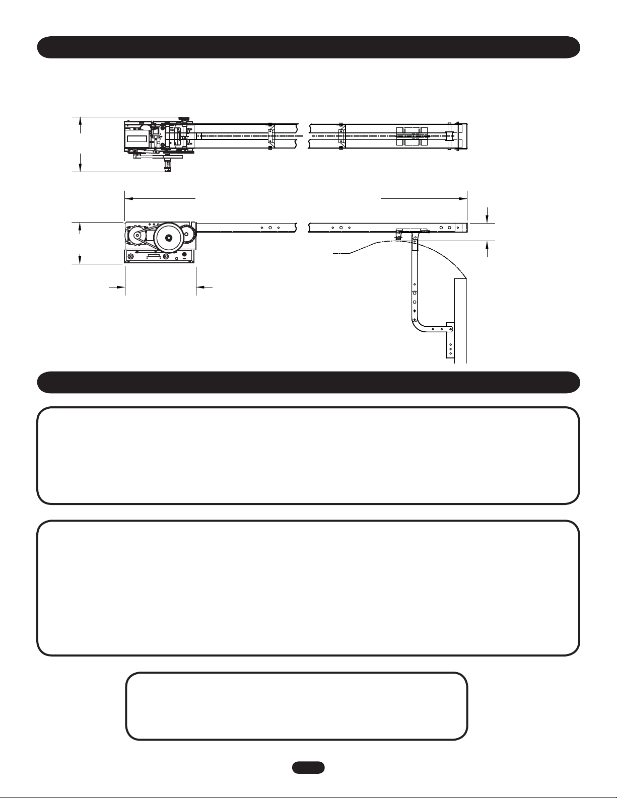
WEIGHTS AND DIMENSIONS
HANGING WEIGHT:80-110 LBS. (36.29-49.9 kg) (Including Track)
9-1/2"
(24.13 cm)
Door Height Plus 4 feet (1.22 m) (minimum)
16-3/16"
(41.12 cm)
Path Of Highest Point On
Door
4"
(10.16 cm)
12-1/2"
(31.75 cm)
OPERATOR SPECIFICATIONS
SAFETY
DISCONNECT . . . . . . . . . . . . . . . . . . Quick disconnect door arm
for emergency manual door operation.
ENTRAPMENT PROTECTION: . . . . Supports both monitored and
non-monitored safety devices including LiftMaster CPS
photo-eyes and industry standard sensing edges.
MOTOR
TYPE: . . . . . . . . . . . . . . . . . . . . . . . . . . . . . . . . . . . Limited duty
HORSEPOWER: . . . . . . . . . . . . . . . . . . . . . . . . 1/2 Horsepower
VOLTAGE: . . . . . . . . . . . . . . . . . . . . 115Vac, Single Phase, 60Hz
FULL LOAD AMPS:. . . . . . . . . . . . . . . . . . . . . . . . . . . 6.0 Amps
ELECTRICAL
OPERATOR VOLTAGE: . . . . . . . . . 115 Vac, Single Phase, 60 Hz
WIRING TYPE: . . . . . . . C2 Standard B2 configurable (see Basic
Programming section)
CONTROL WIRING: . . . . . . . . . . . . . . . . . . . . . . . . . .16-22 AWG
MECHANICAL
DOOR SPEED:. . . . . . . . . . . . . . . . . . . . 12" (30.48 cm) / second
OUTPUT FORCE:. . . . . . . . . . . . . . . . . . . . . . . . . 125 ft. lbs/ sec.
BRAKE (BMT ONLY): . . . . . . . . . . Solenoid actuated disc brake
LIMIT ADJUST:. . . . . .Fully adjustable up to 14' door maximum
DUTY: . . . . . . . . . . . . . . . . . . . . . .12 Cycles per hour maximum
50 Cycles per day maximum
BEARINGS: . . . . . . . . . . . . . . . . . . . . . . . . . . . Maintenance Free
FINISH: . . . . . . . . . . . Powder coated, Corrosion Resistant Steel
ENVIRONMENTAL
LOCATION: . . . . . . . . . . . . . . . . . . . . . . . . . . . . . . . . . . . . . . . Indoor, dry location
OPERATING TEMPERATURE: . . . . . . . . . . . . . . . -4˚ F to +122˚F (-20C˚ to + 50˚C)
OPERATOR DIMENSIONS
5
PREPARATION
PREPARING YOUR DOOR
The manufacturer recommends 3' (91.4 cm) of clearance around
the operator for serviceability. Before you begin:
• Disable locks.
• Remove any ropes connected to door.
• Before the operator is installed, be sure the door has been
properly aligned and is working smoothly. Although each
installation will vary due to particular building characteristics,
refer to the following general procedures to install the operator.
Before beginning your installation check that all components
were provided.
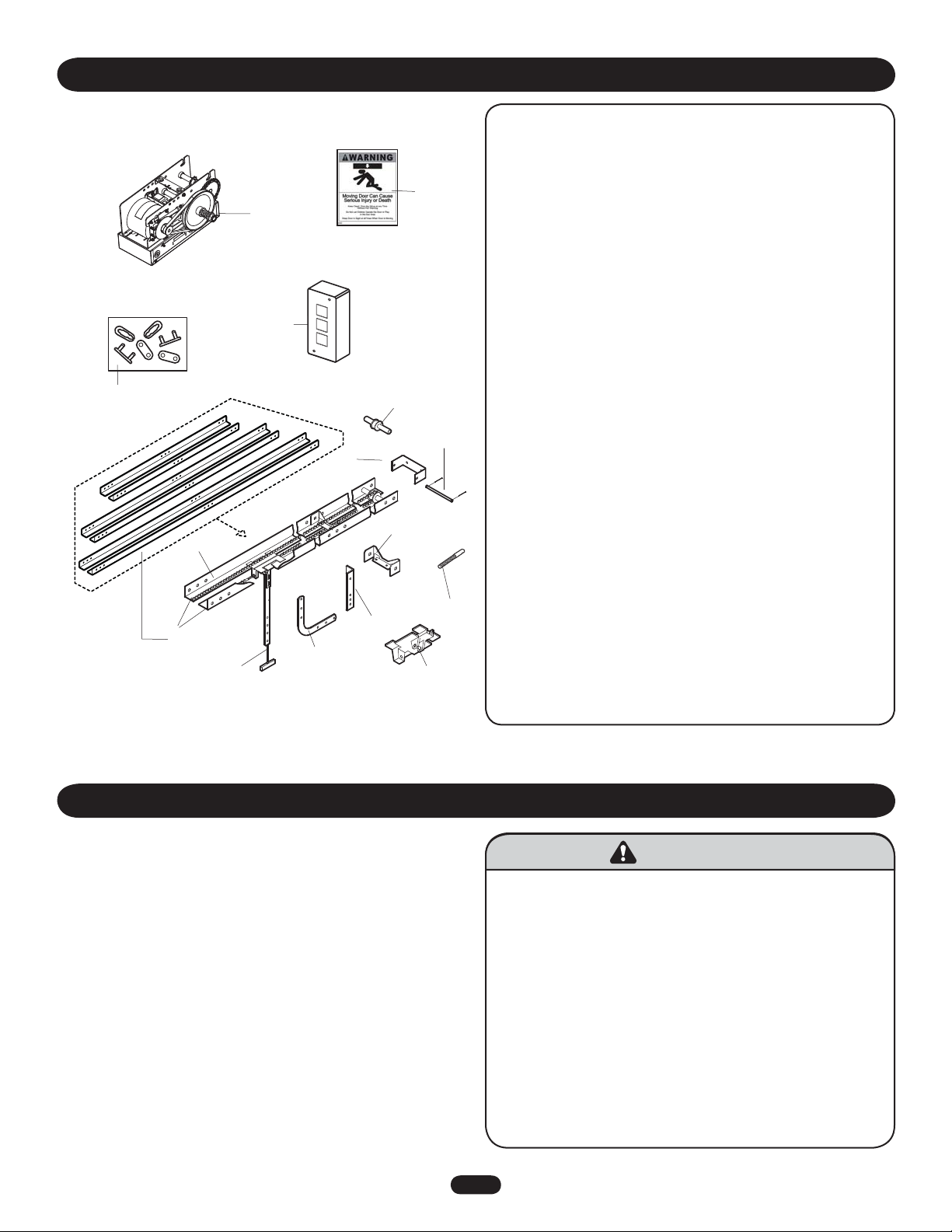
CARTON INVENTORY
To prevent possible SERIOUS INJURY or DEATH:
• DO NOT connect electric power until instructed to do so.
• If the door lock needs to remain functional, install an
interlock switch.
• ALWAYS call a trained professional door serviceman if door
binds, sticks or is out of balance. An unbalanced door may
not reverse when required.
• NEVER try to loosen, move or adjust doors, door springs,
cables, pulleys, brackets or their hardware, ALL of which are
under extreme tension and can cause SERIOUS personal
INJURY.
• Disable ALL locks and remove ALL ropes connected to door
BEFORE installing and operating door operator to avoid
entanglement.
^
^
OPEN
CLOSE
O
STOP
NOTE: The tracks are shipped separately. Actual track length
will exceed door height by 2'. Example: The track for
12' door will be 14'.
ITEM DESCRIPTION QTY
1 Operator 1
2 Track (left & right)
Door height plus 2' 2
3 Track Spacers 2
4 Front Idler 1
5 Trolley 1
6 Take-up Bolt 1
7 Chain 1
8 Master Links 2
9 Header Bracket 1
10 Header Pivot Shaft 1
11 Curved Door Arm 1
12 Straight Arm 1
13 Door Bracket 1
14 3-Button Station 1
15 Warning Sign 2
NOT SHOWN
Installation Manual 1
Quickstart Guide 1
User’s Guide 1
Caution Label 1
Installation Hardware Bag 1
Complete with: Bolts 3/8"-16 x 3/4 " (10),
Flanged Hex Nuts 3/8"-16 (14), Bolt 3/8"-16 x 1
(3), Lockwashers 3/8" (3), Cotter Pins (2) and
Carriage Bolts (2)
NOTE: Depending on door height, the quantity of track
spacers and hardware may vary.
1
2
3
4
5
9
8
14
15
13
10
12
6
11
7
WARNINGWARNING
WARNING
6
ASSEMBLY
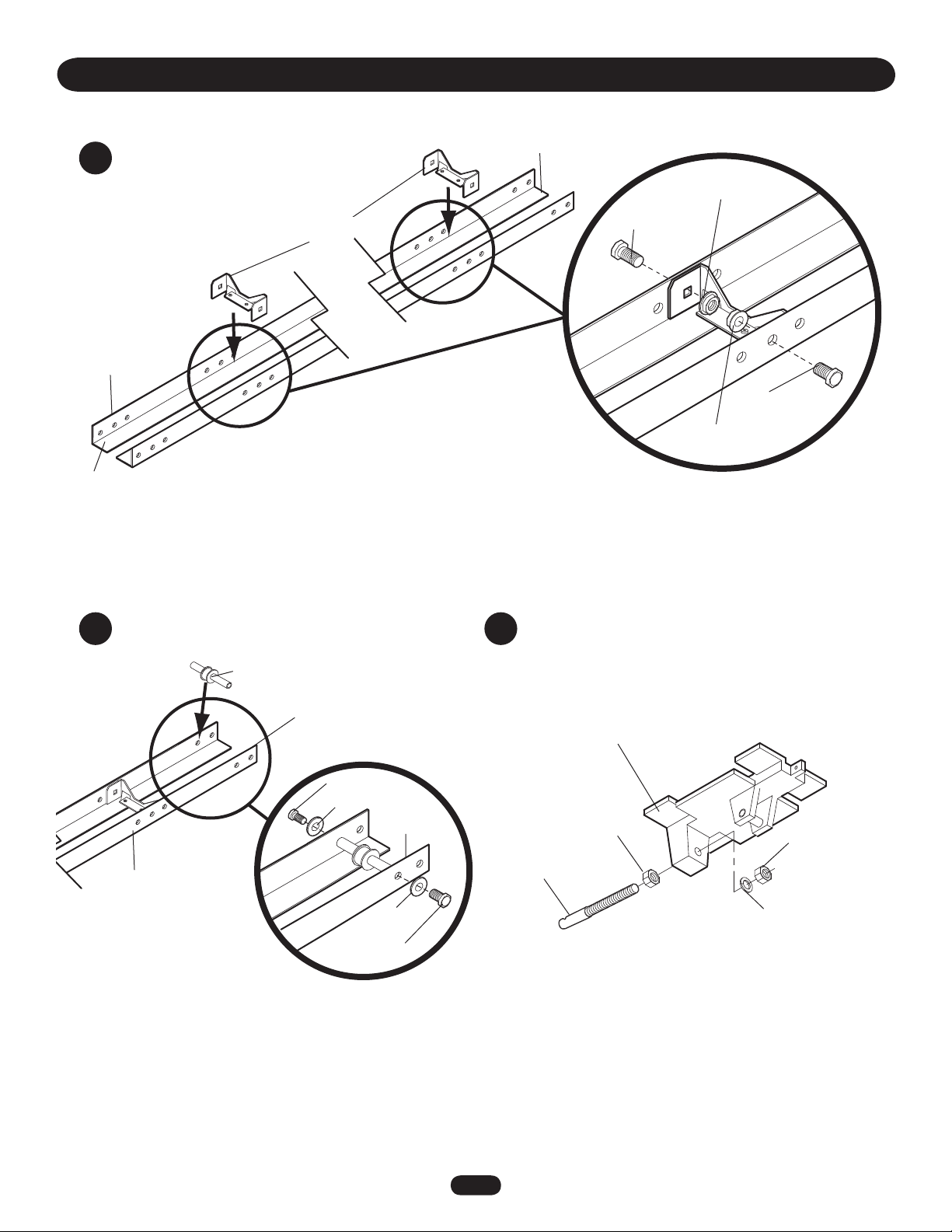
1
2 3
Install track spacers
Install front idler Assemble trolley
Track
Spacers
Track
Bolt
3/8" - 16 x 3/4"
Flange
Hex Nut
Bolt
3/8" - 16 x 3/4"
Flange
Hex Nut
Track
Front Idler
Bolt 3/8" -16 x 1"
Bolt 3/8" -16 x 1"
Lock Washer
Lock
Washer
Trolley
Take-Up Bolt
Flange Nut
3/8" - 16
Flange Nut
3/8" - 16
Lock Washer
Position the track spacers evenly
over the length of the track using
the pre-punched holes. For doors
up to 12' use 2 track spacers, for
14' doors use 3 spacers.
Operator End
Header End
Header End
Header End
7
Track
Bolt
3/8" - 16 x 3/4"
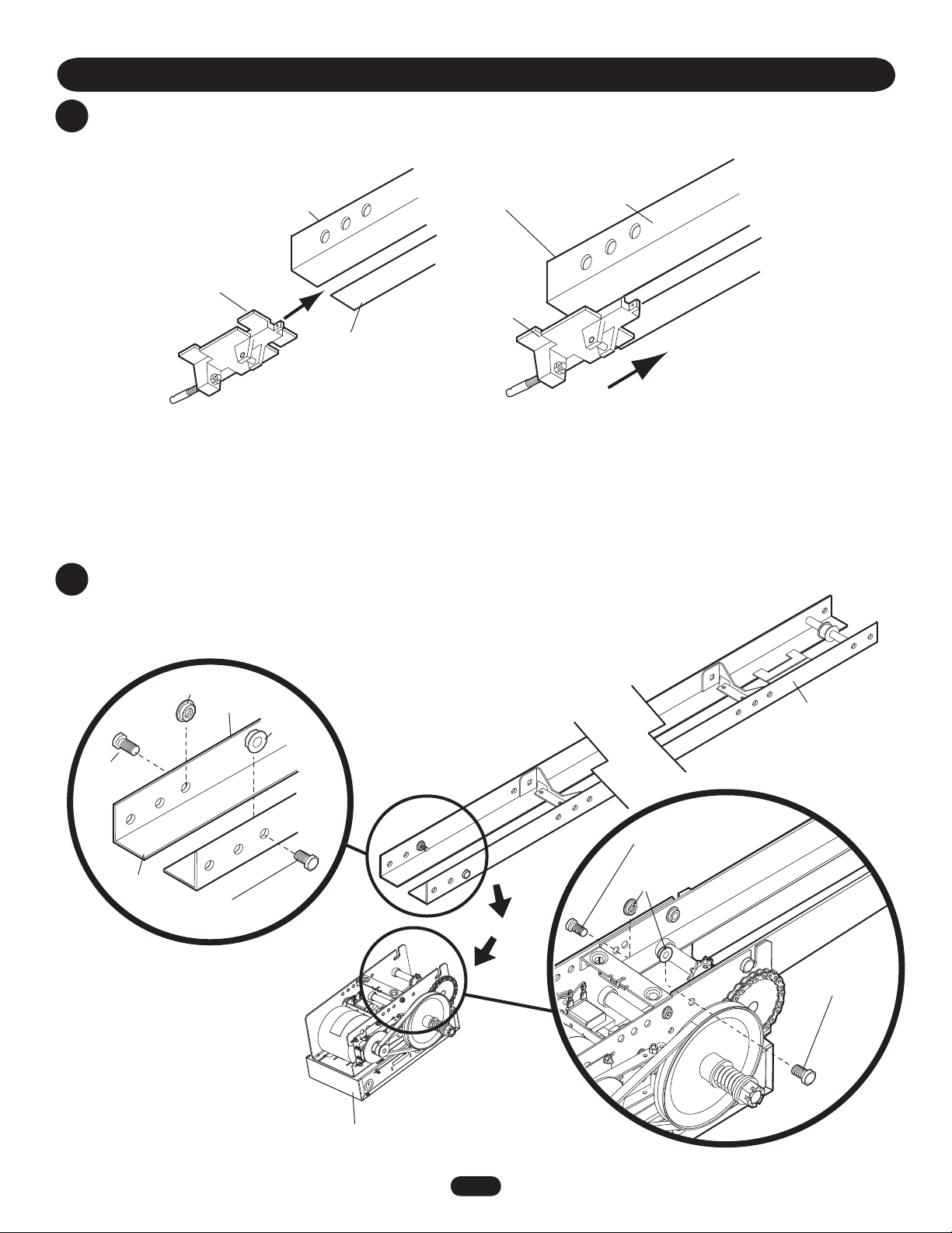
ASSEMBLY
4
Slide trolley onto the track
5
Attach track to operator
Track
Trolley
Operator
Track
Trolley
Operator
End
Operator End
Header
End
Operator
End
Bolt
3/8" - 16 x 3/4"
Bolt
3/8" - 16 x 3/4"
Flange Hex Nut
Flange
Hex Nut
Flange Hex
Nut
Bolt
3/8" - 16 x 3/4"
8
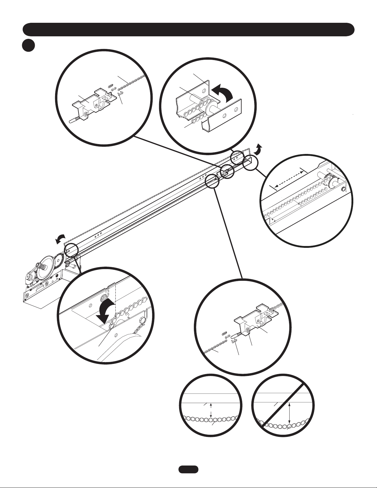
ASSEMBLY
6
Install chain
Trolley
Chain
Master Link
Chain
Front Idler
Track
Wrap chain
around front
idler
Attach chain
to front of
trolley
Trolley
Chain
Master Link
Bottom of
Track
Bottom of
Track
3"
More
than 3"
Attach chain
to back of
trolley
Wrap chain
around drive
sprocket
Drive
Sprocket
Operator
Run chain around
track in the direction
indicated
Adjust the
chain by
tightening the
inner nut
Inner Nut
Slide trolley 2" away from front idler
2"
Chain
Chain
9
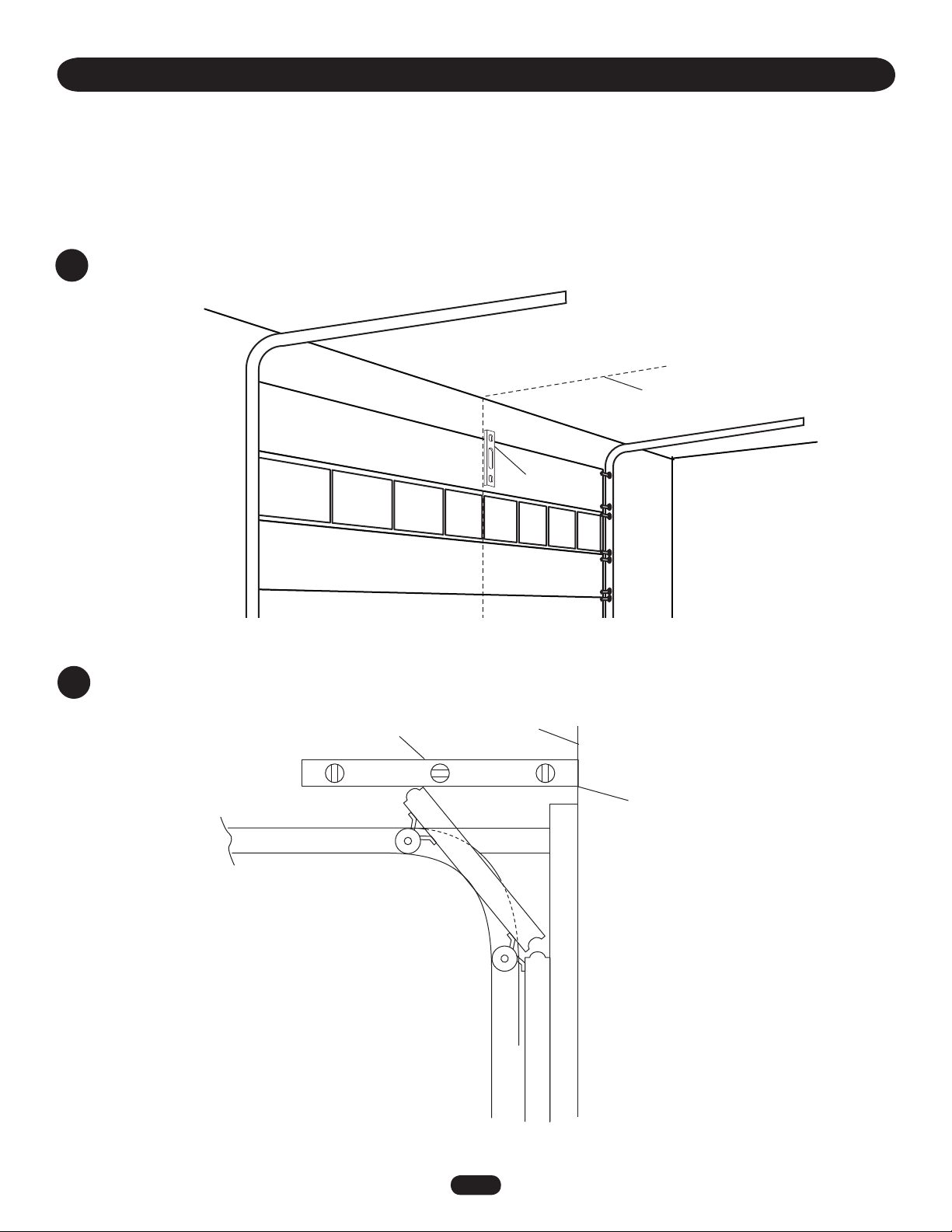
TYPICAL INSTALLATION
DETERMINE HEADER BRACKET MOUNTING LOCATION
The trolley operator is generally mounted over the center of the door. However, off center
mounting may be required due to interfering structures or location of door stile / top section
support. Typically, the operator may be mounted up to 24" (60.96 cm) off center on torsion
spring doors. Extension springs require center mounting.
1
Mark the center of the door
Mark the center line of the door.
Extend the line on to the header wall and
the ceiling.
Level (Optional)
2
Determine and mark the highest point of door travel
Level
High Point of
Door Travel
Header Wall
Loading...