


LGO
Table of contents
 Loading...
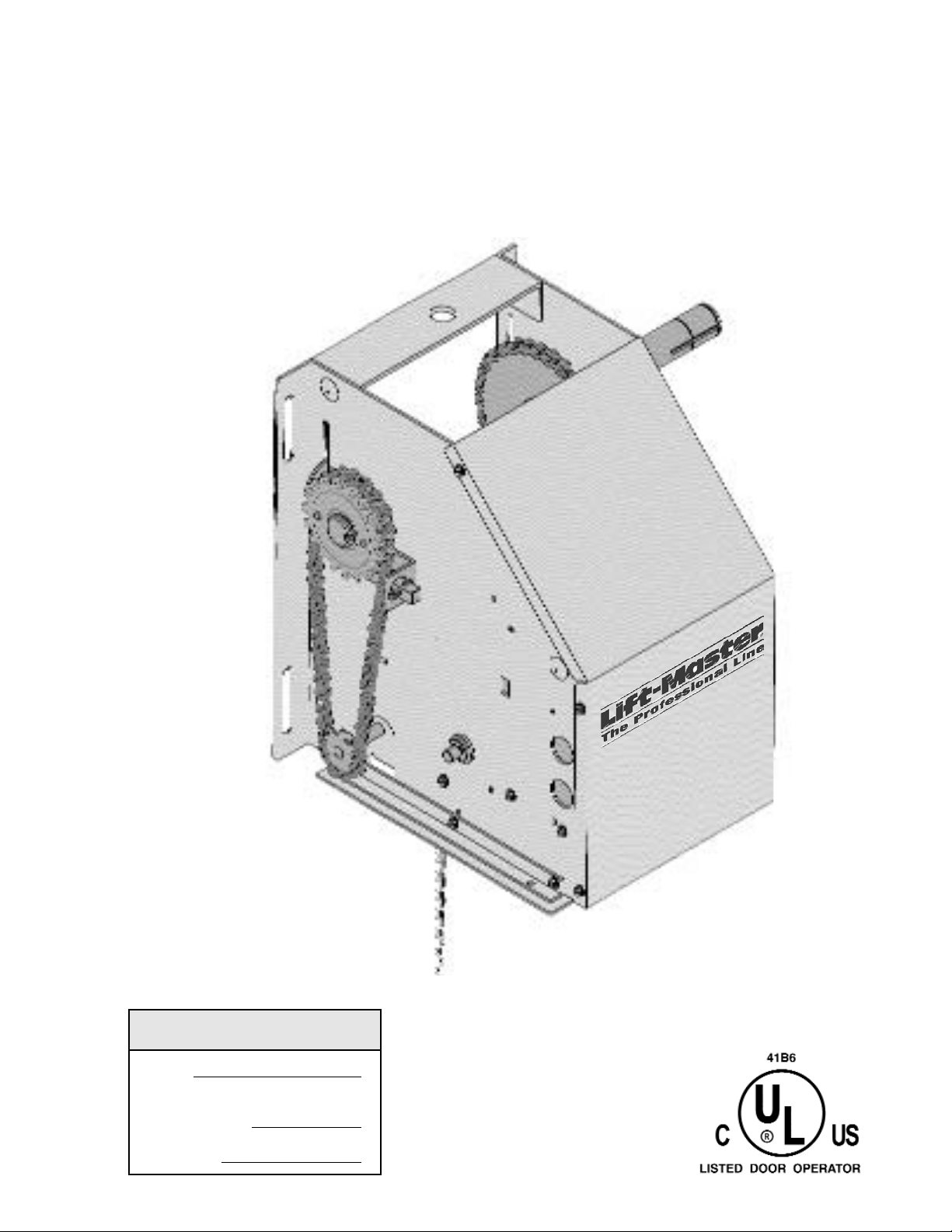
NOT FOR RESIDENTIAL USE
Serial #
(located on electrical box cover)
Installation Date
Wiring Type
2 YEAR WARRANTY
OWNER'S MANUAL
MODEL LGO
LIGHT DUTY GRILL OPERATOR

SPECIFICATIONS
MOTOR
TYPE: ...............................Intermittent duty
HORSEPOWER: ..............1/2 Horsepower
SPEED: ............................1600 RPM
VOLTAGE:........................115V, 1 Phase, 60Hz
CURRENT: .......................See motor nameplate
MECHANICAL
DRIVE REDUCTION:
Primary: ............................Worm Gear 16:1
Secondary:........................#48 chain/ sprocket
Output: ..............................#41 chain.
ELECTRICAL
CONTROL STATION:.......NEMA 1 three button station.
OPEN/CLOSE/STOP or 2 button station OPEN/CLOSE.
RADIO: .............................The internal radio receiver will
not operate in D1 (constant pressure mode)
WIRING TYPES: ..............B2 (Standard) Momentary
contact to open, close and stop, plus wiring for sensing
device to reverse and auxiliary devices to open and
close with open override.
D1 (Optional) ....................Constant pressure to open
and close with wiring for sensing devices to stop.
LIMIT ADJUST: ................Linear driven, fully adjustable
screw type cams. Adjustable to 24 feet.
SAFETY
DISCONNECT: ....................Floor level disconnect for
emergency manual door operation.
PHOTO EYES : ....................Photo eyes to reverse
door.
OUTPUT SHAFT SPEED:.......
DOOR SPEED
door
:....................
40 R.P.M.
9” per sec. depending on
WEIGHTS AND DIMENSIONS
HANGING WEIGHT: .........40-45 LBS.
13.5”
6.75”
6.75”
LIFT MASTER PHOTO EYES P/N CPS-LN4 ARE
STRONGLY RECOMMENDED FOR ALL COMMER-
CIAL OPERATOR INSTALLATIONS. REQUIRED
WHEN ANY OTHER CONTROL (AUTOMATIC OR
MANUAL) IS USED.
9.45”
14.31”
9.00”
11.42”
2
9.00”
SITE PREPARATIONS
TO AVOID DAMAGE TO DOOR AND OPERATOR,
MAKE ALL DOOR LOCKS INOPERATIVE.
SECURE LOCK(S) IN "OPEN" POSITION.
IF THE DOOR LOCK NEEDS TO REMAIN FUNCTIONAL, INSTALL AN INTERLOCK SWITCH.
DO NOT CONNECT ELECTRIC POWER UNTIL
INSTRUCTED TO DO SO.
KEEP DOOR BALANCED. STICKING OR BINDING
DOORS MUST BE REPAIRED. DOORS, DOOR
SPRINGS, CABLES, PULLEYS, BRACKETS AND
THEIR HARDWARE MAY BE UNDER EXTREME
TENSION AND CAN CAUSE SERIOUS PERSONAL
INJURY. CALL A PROFESSIONAL DOOR SERVICEMAN TO MOVE OR ADJUST DOOR SPRINGS
OR HARDWARE.
WARNING
CAUTION
WARNING
WARNING
WARNING
It is imperative that the wall or mounting surface provide
adequate support for the operator.
This surface must:
a) Be rigid to prevent play between operator
and door shaft.
b) Provide a level base.
c) Permit the operator to be fastened
securely and with the drive shaft parallel
to the door shaft.
The safety and wear of the operator will be adversely
affected if any of the above requirements are not met.
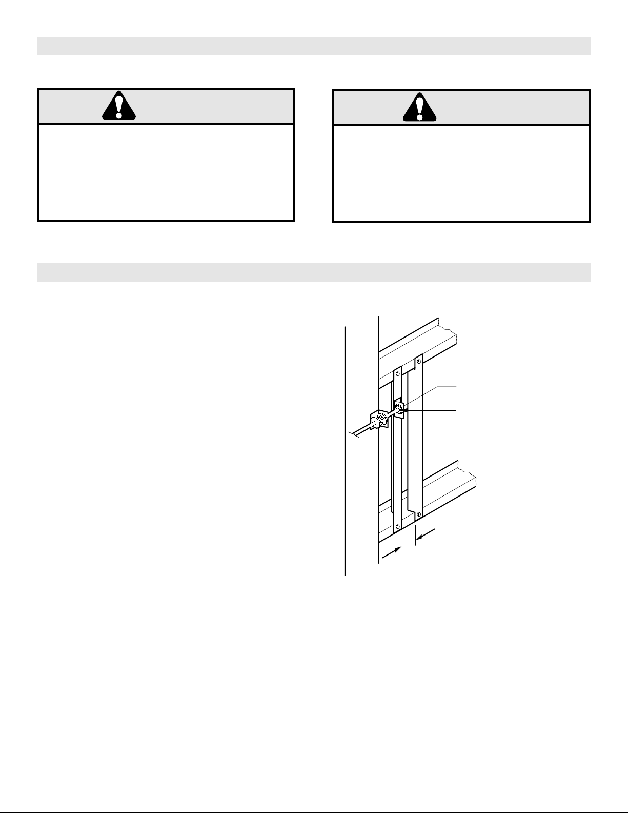
For metal buildings, fasten 2” x 2” x 3/16” (or larger) angle
iron frames to the building purlins. Retain 7” between
frames. Refer to figure 1.
7.00”
3
IMPORTANT SAFETY NOTES
CAUTION
WARNING
Shaft Support Bracket
with Bearing (Not Supplied)
Door Sprocket
2-1/4"
FIGURE 1
OPERATOR MOUNTING
Before your operator is installed, be sure the door has been properly aligned and is working smoothly. The operator may
be wall mounted or mounted on a bracket or shelf. If necessary, refer to the operator preparations on page 3. Refer to
the illustration and instructions below that suits your application.
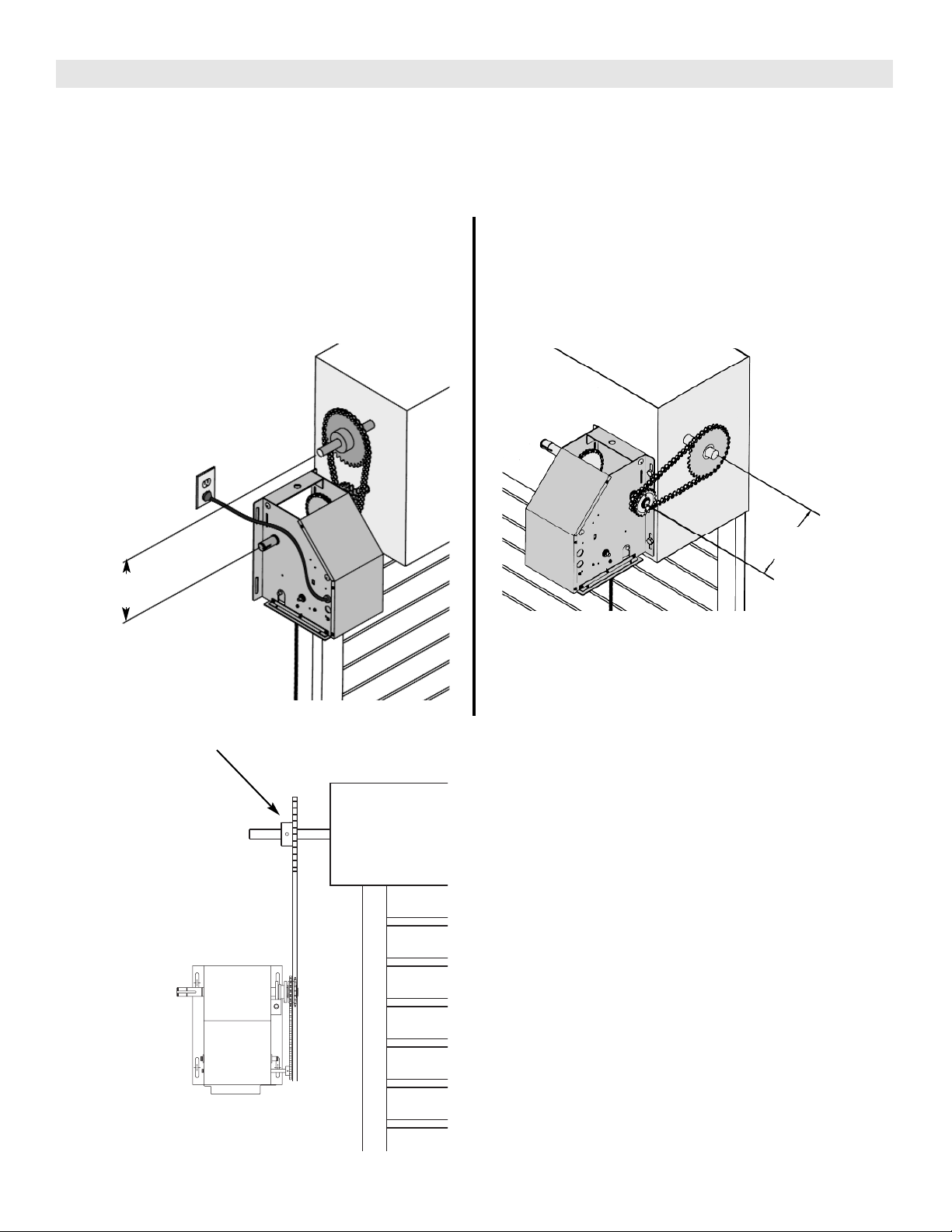
1a. Wall Mounting
The operator should generally be installed below the
door shaft, and as close to the door as possible. The
optimum distance between the door shaft and opera
tor drive shaft is between 12” - 15”. Refer to figure 2.
FIGURE 2
OPTIMUM DISTANCE
12-15”
1b. Bracket or Shelf Mounting
The operator may be mounted either above or below
the door shaft. The optimum distance between the
door shaft and operator drive shaft is between 12” 15”. Refer to figure 3.
FIGURE 3
OPTIMUM DISTANCE
12-15”
IMPORTANT: The shelf or bracket must provide adequate support, prevent play between
operator and door shaft, and permit operator
to be fastened securely and with the drive
shaft parallel to the door shaft.
Be sure door sprocket is
properly aligned with
drive sprocket before
securing to the shaft.
FIGURE 4
IMPORTANT: The shelf or bracket must provide adequate support, prevent play between operator and
door shaft, and permit operator to be fastened
securely and with the drive shaft parallel to the door
shaft.
1c. Place door sprocket on the door shaft. Do not insert
the key at this time.
2. Place drive sprocket on the appropriate side of the
operator.
3. Wrap drive chain around door sprocket and join roller
chain ends together with master link.
4. Raise operator to approximate mounting position and
position chain over operator sprocket.
5. Raise or lower operator until the chain is taut (not
tight). Make sure the operator output shaft is parallel
to door shaft and sprockets are aligned. When in
position, secure the operator to wall or mounting
bracket.
6. Insert keys and align sprockets and secure. Refer to
figure 4.
4

5
EMERGENCY MANUAL OPERATION
This operator has a floor level disconnect chain to disconnect the door from the door operator.
a) To disengage, pull the chain and secure in the disengaged position by slipping the end through the keyhole
bracket mounted on the wall. Or if emergency egress
device is used, pull handle to disengage operator from
the door.
b) The door may now be pushed up or pulled down
manually. Release the disconnect chain to operate the
door again electrically. Refer to figure 5.
KEYHOLE BRACKET
FIGURE 5
DOOR OPERATING SYSTEM ILLUSTRATION
ALTERNATE MOUNTING
FOR OPTIONAL PHOTO EYES
RIGID MOUNTING SURFACE
TO ADJUST
TENSION
KEYHOLE
BRACKET
MOUNTING HARDWARE
NOT SUPPLIED
TRACK MOUNT
FLOOR MOUNT
WALL MOUNT
PULL CHAIN FOR
MANUAL OPERATION

POWER WIRING
THREE PRONG GROUNDING PLUG
To reduce the risk of shock, this operator has a grounding
type plug, that has a third (grounding) pin. This plug will
only fit into a grounding type outlet. If this plug does not
fit into the outlet, contact a qualified electrician to install
the proper outlet. Do not change the plug in any way.
Refer to figure 6.
PERMANENT WIRING
If permanent wiring is required by your local code,
refer to the following procedure:
To make a permanent connection through the 7/8” diameter hole in the side of the operator:
1. Remove the opener cover screws and set the cover
aside. Refer to figure 8.
2. Remove the 3-prong cord.
3. Connect the black (line) wire to the screw on the brass
terminal; the white (neutral) wire to the screw on the
silver terminal; and the ground wire to the green
ground screw. The opener must be grounded. Refer
to figure 7.
4. Re-install the cover.
To prevent electrocution, remove power from the
garage door opener and from the circuit you plan to
use for the permanent connection.
FIGURE 6
FIGURE 7
GROUND WIRE
GROUND
SCREW
BLACK
WIRES
FIGURE 8
LOOSEN 2 COVER SCREWS FOR ACCESS
TO POWER/ CONTROL WIRING AND LIMIT/
FORCE ADJUSTMENTS.
WHITE
WIRES
6
7
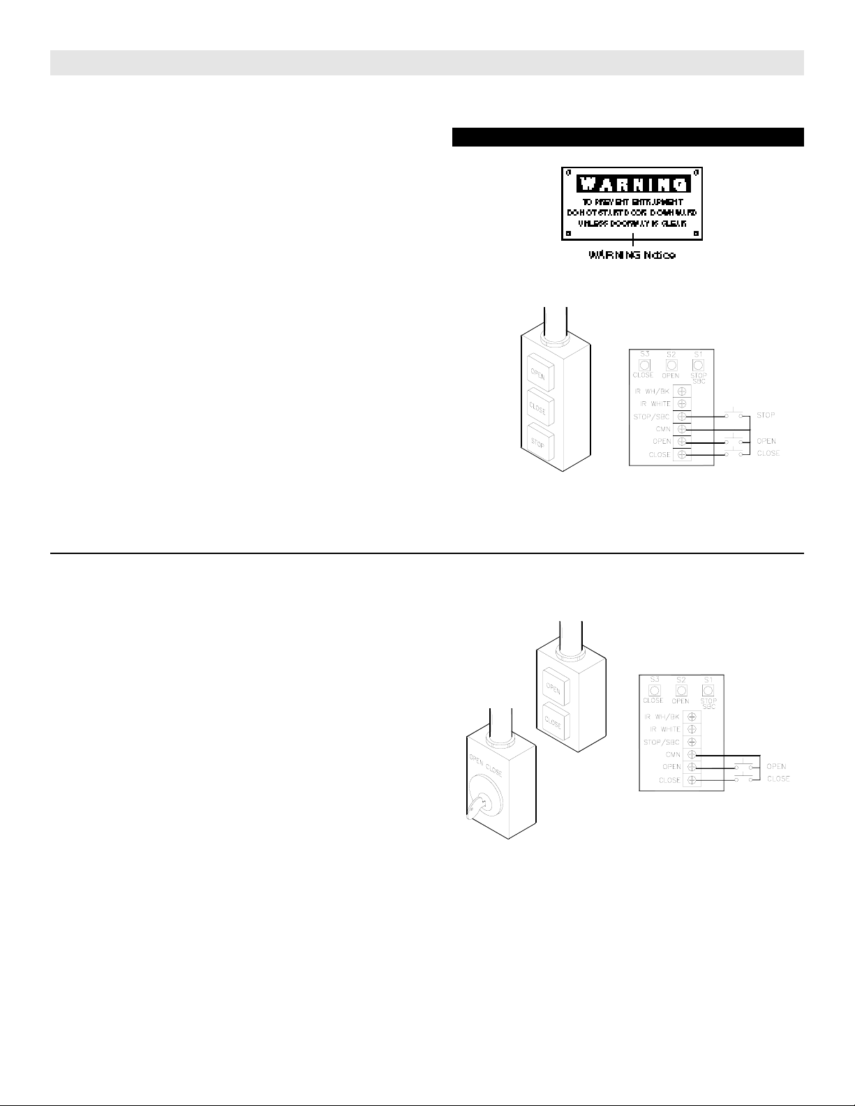
INSTALLATION OF DOOR CONTROLS
TWO-BUTTON/TWO POSITION KEY SWITCH:
Operator must be programmed to D1 Mode, See programming instructions below.
1. Locate the door control within sight of the door at a
minimum height of 5 feet where small children cannot
reach, and away from all moving parts of the door and
door hardware.
2. Fasten the door control button securely with 6AB X 1-
1/2” screws. If installing into drywall, drill 5/32” holes and
use anchors provided.
3. Run the wire up the wall to the opener. Use insulated
staples to secure the wire in several places. Be careful
not to pierce the wire with a staple.
4. Receiver terminal screws are located inside the oper-
ator access panel on the interface board. Connect each
wire to the corresponding interface board terminals- The
“OPEN” terminal of the wall control connects to “OPEN”,
the “CLOSE” terminal of the wall control connects to
“CLOSE”, and the common terminal of the wall control
connects to “CMN”. Refer to figure 10.
THREE BUTTON STATION (STANDARD)
Operator must be programmed to B2 Mode, See programming instructions below.
1. Locate the door control within sight of the door at a
minimum height of 5 feet where small children cannot
reach, and away from all moving parts of the door and
door hardware.
2. Fasten the door control button securely with 6AB X 1-
1/2” screws. If installing into drywall, drill 5/32” holes and
use anchors provided.
3. Run the wire up the wall to the opener. Use insulated
staples to secure the wire in several places. Be careful
not to pierce the wire with a staple.
4. Receiver terminal screws are located inside the oper-
ator access panel on the interface board. Connect each
wire to the corresponding interface board terminals- The
“OPEN” terminal of the wall control connects to “OPEN”,
the “CLOSE” terminal of the wall control connects to
“CLOSE”, the “STOP” terminal connects to “SBC /
STOP”, and the common terminal of the wall control connects to “CMN”. Refer to figure 9.
MOUNT WARNING NOTICE
FIGURE 10
FIGURE 9

PROGRAMMING OPERATING MODES
To Change Operating Modes: (Factory Set to B2 Mode)
1. Press and hold the LEARN button (The learn LED will light).
NOTE: IF THE LEARN/MODE BUTTON IS HELD FOR 5 SECONDS, ALL LEARNED TRANSMITTERS WILL BE
ERASED.
2. To learn the appropriate mode: While holding the LEARN button, press the corresponding button on the interfaceboard.
B2 Mode: CLOSE Button (S3)
D1 Mode: OPEN Button (S2)
3. Release both buttons. The LEARN LED gives a visual indication of the mode programmed.
B2 Mode = 2 Blinks
D1 Mode = 1 Blink
IMPORT
connected and sending a pulse prior to programming. See programming instructions above.
ANT NOTE: When optional photo eyes (IR’s) are used, Wiring Mode B2 must be reprogrammed. IR’s must be
SAFETY EDGE
SENSING EDGES
All types of sensing edges with an isolated normally open
(N.O.) output are compatible with your operator. This
includes pneumatic and electric edges. If your door does
not have a bottom sensing edge and you wish to purchase one, contact the supplier of your operator.
If not pre-installed by the door manufacturer, mount the
sensing edge on the door according to the instructions
provided with the edge. The sensing edge may be electrically connected by either coiled cord or take-up reel.
Refer to the steps below.
Important Notes:
a) To install a sensing edge, ask for sensing edge con-
nection kit LGOSE. This must be installed in order to
add a sensing edge. Refer to instructions and figure 11 on page 9.
b) Proceed with Limit Switch Adjustments before making
any sensing edge wiring connections to operator as
described below.
c) Electrician must hard-wire the junction box to the oper-
ator electrical box in accordance with local codes.
TAKE-UP REEL: Take-up reel should be installed 12"
above the top of the door.
COIL CORD: Connect operator end of coil cord to junction box (not supplied) fastened to the wall approximately halfway up the door opening.
8

9
CONNECTING SAFETY EDGE
IR WH/BK
IR WHITE
STOP/SBC
CMN
OPEN
CLOSE
CLOSE OPEN STOP
S3 S2 S1
a) Run the wires from the edge to the operator. Use a take-up reel or coil cord for this purpose.
b) Refer to local codes for all wiring requirements.
c) Connect one side of the edge to the sensing edge cutout switch (white wire) using the wire nut supplied.
d) Connect the other side of the sensing edge to the interface board (IR WH/BK) terminal.
e) Run the door in the close direction, activate edge, and confirm that the door reverses. Refer to figure 11.
SENSING EDGE
SWITCH
EDGE
WIRE
NUT

LIMIT ADJUSTMENTS
1. To adjust limit nuts depress retaining plate to allow nut
to spin freely. After adjustment, release plate and
ensure it seats fully in slots of both nuts.
2. To increase door travel, spin nut away from actuator.
To decrease door travel, spin limit nut toward
actuator.
TO AVOID SERIOUS PERSONAL INJURY OR DEATH
FROM ELECTROCUTION, DISCONNECT ELECTRIC
POWER BEFORE MANUALLY MOVING LIMIT NUTS.
3. Adjust open limit nut so that door will stop in open
position with the bottom of the door even with top of
door opening.
4. Repeat Steps 1 and 2 for close cycle. Adjust close limit
nut so that actuator is engaged as door fully seats at
the floor. Refer to figure 12.
FIGURE 12
MAKE SURE THE LIMIT NUTS ARE POSITIONED BETWEEN THE LIMIT
SWITCH ACTUATORS BEFORE PROCEEDING WITH ADJUSTMENTS.
If other problems persist, call our toll-free number for
assistance 1 (800)528-2806
FORCE ADJUSTMENTS
The open/down force adjustments are made by adjusting
two control knobs inside the operator end panel. One
knob controls the drive force adjustment. The second
knob controls the sensitivity, which is the change of force
as seen by the operator.
To set the forces
1. Adjust the drive force to minimum and the sensitivity
to minimum.
2. Increase the drive force in 10 degree increments until
the door travels freely from limit to limit.
3. Increase the sensitivity in 10 degrees until the door
begins to reverse/stop in mid-travel.
4. Decrease the sensitivity by 10 degrees and run the
door through a complete cycle to confirm normal
operation. Refer to figure 13.
If the door stops normal travel of open/close to the limits,
decrease the dive and sensitivity knobs to minimum and
repeat steps 2 through 4.
FIGURE 13
10
DRIVE FORCE
SENSITIVITY
Loading...