


 Loading...
The Chamberlain Group, Inc.
A DUCHOSSOIS ENTERPRISE
845 Larch Avenue
©
Elmhurst, Illinois 60126
OWNER'S MANUAL
SERIES 1000
MODEL MT 1211
MEDIUM DUTY
BELT DRIVEN TROLLEY OPERATOR
3 |
2 |
1 |
Serial # |
|
|
|
|
|
|
|
(located on electrical box cover) |
|
|
|
||||
Installation Date |
|
|
|
|
COMMERCIAL DOOR OPERATOR |
||
|
|
® |
|
LISTED |
|||
|
|
||||||
Wiring Type |
|
|
|
® |
|||
|
|
|
|
NOT FOR RESIDENTIAL USE |
|||
|
|
|
|
||||
|
|
|
|
|
|
|
|
SPECIFICATIONS
|
MOTOR |
|
ELECTRICAL |
|
TYPE: ................................ |
Permanent Split Capacitor |
TRANSFORMER: |
..........24VAC |
|
HORSEPOWER: ............... |
1/2 HP Intermittent Duty |
CAPACITOR: ................. |
Single 70 microfared |
|
|
(12 Cycles/Hr.) |
CONTROL STATION: 3 Button |
||
SPEED: |
1000 RPM |
|||
|
OPEN/CLOSE/STOP, NEMA 1 |
|||
VOLTAGE: ........................ |
115VAC 60Hz Single Phase |
WIRING TYPE:............... |
B2 (Standard) |
|
CURRENT: |
6.0/6.5 AMP |
Momentary Contact to OPEN/CLOSE/STOP plus |
||
Wiring for Sensing Device to Reverse and Auxiliary |
||||
MAXIMUM |
|
|||
|
Devices to Open and Close with Opener Override |
|||
DOOR SIZE:...................... |
14' X 14' |
LIMIT ADJUST: |
Linear Driven, Fully |
|
|
|
|||
Adjustable Screw Type Cams. Adjustable to 14 feet.
|
|
|
|
|
|
|
|
MECHANICAL |
|
|
SAFETY |
|
|
|
DRIVE REDUCTION: |
|
|
DISCONNECT:.................. |
Spring Loaded Trolley |
|
|
1st Reduction: |
Heavy Duty (4L) V-Belt |
|
|
Disconnect Arm |
|
|
|
|
|
|
||
|
2nd & 3rd Reductions: |
#48 Chain and Sprockets |
|
CLUTCH:........................... |
Adjustable Friction Type |
|
|
|
|
|
|
||
|
Output: |
#48 Chain |
|
SAFETY EDGE: ................ |
(Optional) |
|
|
|
Electric or Pneumatic Sensing Device attached to the |
|
|||
|
OUTPUT SHAFT SPEED: |
|
|
|
||
|
85 R.P.M. |
|
Bottom Edge of Door. |
|
||
|
DOOR SPEED:.................... |
8" - 10" per sec. |
|
A REVERSING EDGE IS STRONGLY |
|
|
|
BEARINGS: |
Heavy Duty Oil-Filled Bronze |
|
RECOMMENDED FOR ALL COMMERCIAL |
|
|
|
|
OPERATOR INSTALLATIONS. REQUIRED WHEN |
|
|||
|
|
|
|
|
||
|
BRAKE: ............................... |
Solenoid Drum Brake |
|
THE 3 BUTTON CONTROL STATION IS OUT OF |
|
|
|
|
(Optional) |
|
SIGHT OF DOOR OR ANY OTHER CONTROL |
|
|
|
|
|
|
(AUTOMATIC OR MANUAL) IS USED. SEE PAGE 8. |
|
|
|
|
|
|
|
|
|
|
|
|
|
|
|
|
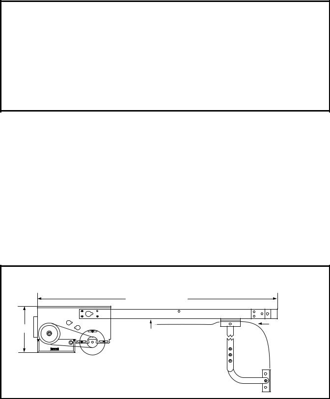
WEIGHTS AND DIMENSIONS
HANGING WEIGHT.....42 LBS.
DOOR HEIGHT + 3' - 3 1/2"
11 1/2" |
MIN. CLEARANCE OF 2" FROM HIGH ARC OF DOOR TO BOTTOM OF TRACK
HOW TO ORDER REPAIR PARTS
OUR LARGE SERVICE ORGANIZATION
SPANS AMERICA
INSTALLATION AND SERVICE INFORMATION
ARE AVAILABLE 6 DAYS A WEEK
CALL OUR TOLL FREE NUMBER - 1-800-528-6563 HOURS 7:00 TO 3:30 p.m. (Mountain Std. Time)
MONDAY Thorough SATURDAY
WHEN ORDERING REPAIR PARTS
PLEASE SUPPLY THE FOLLOWING INFORMATION
PART NUMBER DESCRIPTION MODEL NUMBER
ADDRESS ORDER TO:
THE CHAMBERLAIN GROUP, INC.
Electronic Parts & Service Dept.
2301 N. Forbes Blvd., Suite 104
Tucson, AZ 85745
2

ASSEMBLE TRACK AND OPERATOR
 CAUTION
THIS IS A MEDIUM USE OPERATOR, NOT INTENDED FOR RESIDENTIAL OR HIGH USE APPLICATIONS. TO PREVENT ELECTRICAL COMPONENT DAMAGE AND RELATED POTENTIAL HAZARD, DO NOT EXCEED TWELVE (12) CYCLES PER HOUR.
DO NOT CONNECT ELECTRIC POWER UNTIL INSTRUCTED TO DO SO.
 WARNING
KEEP DOOR BALANCED. STICKING OR BINDING DOORS MUST BE REPAIRED. DOORS, DOOR SPRINGS, CABLES, PULLEYS, BRACKETS AND THEIR HARDWARE MAY BE UNDER EXTREME TENSION AND CAN CAUSE SERIOUS PERSONAL INJURY OR DEATH. CALL A PROFESSIONAL DOOR SERVICEMAN TO MOVE OR ADJUST DOOR SPRINGS OR HARDWARE.
FIGURE 1
Header
Idler Shaft Bracket
Bracket
Track Idler
Shaft
Track |
Trolley |
|
Track
Spacer
3 |
2 |
1 |
|
|
Check the identification tag mounted on the electrical box to be sure the voltage, phase and h.p. are correct for your needs.
1.Fasten track to the operator frame. DO NOT TIGHTEN BOLTS. See Figure 1.
2.Position the slide on the track. Attach track spacer(s).
3.Position the idler shaft between tracks. Place track bracket over tracks. There are two holes on each side of bracket (Fig. 1).
Fasten track bracket to end of rail assembly.
REFER TO MASTER WIRING DIAGRAM ON PAGE 10. MAKE CONNECTION THROUGH THE 7/8" DIA., LABELED HOLE. CONNECT THE HOT WIRE TO L1 - THE NEUTRAL WIRE TO L2 - AND THE GROUND WIRE TO THE GREEN CHASSIS GROUND SCREW. DO NOT RUN CONTROL WIRES IN THE SAME CONDUIT AS THE POWER WIRES.
4.Align track so that slide moves easily and does not bind. Tighten all bolts.
5.Run chain around front and rear sprockets and attach to slide assembly with master links. Adjust chain only until excessive slack is removed. To retain proper tension, tighten 3/8" lock nut.
3
INSTALL OPERATOR
CAUTION: AT LEAST TWO PERSONS AND A STRONG, SAFE WORKING PLATFORM ARE REQUIRED FOR THE INSTALLATION OF OPERATOR.
 CAUTION
TO AVOID DAMAGE TO DOOR AND OPERATOR, MAKE ALL DOOR LOCKS INOPERATIVE. SECURE LOCK(S) IN "OPEN" POSITION.
IF THE DOOR LOCK NEEDS TO REMAIN FUNCTIONAL, INSTALL AN INTERLOCK SWITCH.
DO NOT RUN THE OPERATOR BEFORE MAKING LIMIT SWITCH ADJUSTMENTS.
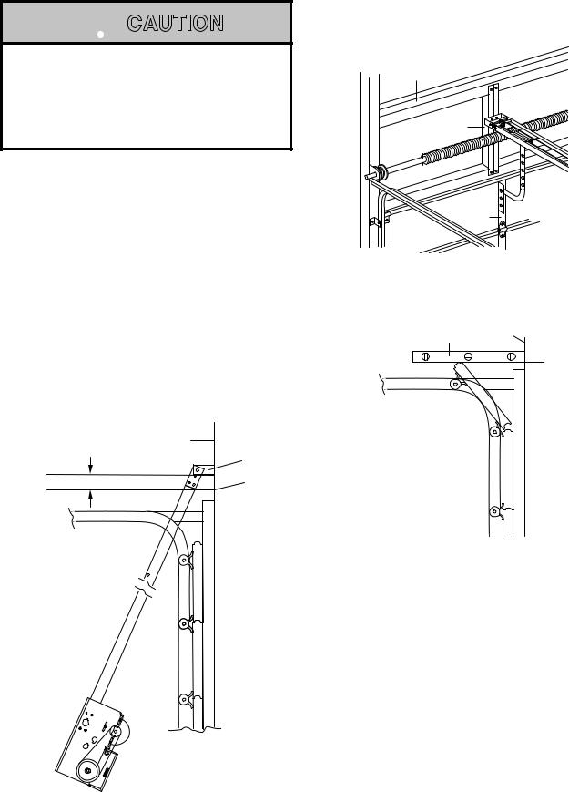
FOR METAL BUILDINGS ONLY: A strong mounting surface for the operator front header bracket is needed. On the wall above the center stile, weld or bolt a 2"x2"x1/4" piece of angle iron or another suitable, heavy-duty material as shown in Figure 2.
6.Draw a vertical line on header (or reinforcement material) above center stile of door.
7.Raise the door to its high arc point. Use a carpenter's level to locate high arc point on wall above door center stile as shown in Figure 3. Make a horizontal line, intersecting the vertical centerline mark.
|
Header |
2" |
Wall |
Header |
|
|
Bracket |
|
High Arc |
|
Point of Door |
FIGUREFIGURE4 |
3 |
FIGURE 2
Building
Support
Vertical
Centerline
2"x 2"x 1/4" Angle Iron
Center
Stile
Carpenter's Header
Level Wall
High Arc
Point
FIGUREFIGURE3 2
8.Close the door and refer to Figure 4. Position operator chassis on the floor with the bottom edge of header bracket 2" above horizontal mark and centered on vertical line. Mark mounting holes.
FOR METAL BUILDINGS: Drill 3/8" holes for fastening bolts. FOR CONCRETE BUILDINGS: Drill 3/8" holes for anchor bolts, following manufacturer's instructions.
NOTE: Be sure header bracket is level before tightening the bolts.
4

9.Raise operator straight up until the door can be raised to the full open position. See Figure 5. Temporarily secure to ceiling or rafters with rope or other suitable means.
 WARNING
FAILURE TO SUSPEND THE OPERATOR SECURELY MAY RESULT IN SERIOUS PERSONAL INJURY OR DEATH, AND/OR PROPERTY DAMAGE.
10.Raise door to full open position. Place a 2x4 board on top of leading edge of door. Lower operator to rest on 2x4 board.
Make four hangers from 2"x2"x1/4" angle iron. IT IS
RECOMMENDED THAT RAIL BE CENTERSUPPORTED AS WELL. Bolt the operator into place.
COIL CORD (OPTIONAL)
REFER TO (A) IN ILLUSTRATION
Connect operator end of coil cord to junction box (not supplied) fastened to the wall approximately half-way up the door opening.
Electrician must hardwire the junction box to the operator electrical box in accordance with local codes.
REEL (OPTIONAL)
REFER TO (B) IN ILLUSTRATION
Take-up reel should be installed 12" above the top of the door.
Building
Support
2"x2"x1/4" Angle Iron
Wire 24V
Trolley
Door |
|
Arm |
Track |
|
|
Door |
Spacer |
|
|
Bracket |
|
|
Rope |
Release |
|
Center |
Air Hose |
Stile |
Reversing |
FIGURE 5 |
Edge |
B
Hanger Angles
2"x2"x1/4"
A


Pneumatic Air Switch
Not Required or Supplied
When Electric Reversing
Edge is Used
5
Loading...