


 Loading...
PREMIUM Series
Belt Drive Garage Door
Opener
Model 8355 - 1/2 hp
FOR RESIDENTIAL USE ONLY |
■ Please read this manual and the enclosed safety materials carefully! |
|
■ Fasten the manual near the garage door after installation. |
||
|
||
|
■ The door WILL NOT CLOSE unless the Protector System® is connected and properly |
|
|
aligned. |
|
|
■ Periodic checks of the garage door opener are required to ensure safe operation. |
|
|
■ The model number label is located on the front panel of your garage door opener. |
|
|
■ This garage door opener is ONLY compatible with MyQ® and Security 2.0™ |
|
|
accessories. |
|
|
■ ONLY enable the Timer-to-Close* or MyQ® remote operation feature* when |
|
|
the garage door opener is installed on a sectional door. (*Not available on all |
|
|
models) |
|
|
NOTE: If you are installing the garage door opener on a one-piece door, visit |
|
|
www.liftmaster.com for installation instructions. |
|
|
Write down the following information for |
|
|
future reference: |
|
|
Serial Number: |
|
|
. |
|
|
Date of Purchase: |
CONTENTS
Preparation . . . . . . . . . . . . . . . .2-3
Assembly . . . . . . . . . . . . . . . . .4-5
Installation . . . . . . . . . . . . . . . 6-13
Install the Door Control . . . . . . 14-16
Install the Protector System® . . 17-20
Power. . . . . . . . . . . . . . . . . . 21-22
Adjustments . . . . . . . . . . . . . 23-25
Operation . . . . . . . . . . . . . . . . . 26
Features . . . . . . . . . . . . . . . . . . 27
Door Control . . . . . . . . . . . . . 28-29
Remote Control . . . . . . . . . . . 30-31
To Erase the Memory . . . . . . . . . 31
To Open the Door Manually . . . . . 32
Maintenance . . . . . . . . . . . . . . . 32
Troubleshooting. . . . . . . . . . . 33-34
Accessories. . . . . . . . . . . . . . . . 35
Warranty. . . . . . . . . . . . . . . . . . 36
Repair Parts . . . . . . . . . . . . . 37-38
www.liftmaster.com
The Chamberlain Group, Inc.
845 Larch Avenue
Elmhurst, Illinois 60126-1196

Preparation
Safety Symbol and Signal
Word Review
Thisgarage door opener hasbeen designed and tested to offer safe service provided itisinstalled, operated,maintained and tested in strict accordance with the instructionsand warnings contained in thismanual.
When you see these SafetySymbolsand Signal Wordson the following pages,theywill alertyou to the possibilityofserious injury ordeathifyou do notcomplywith the warningsthataccompany them.The hazard maycome fromsomething mechanical or fromelectricshock.Read the warningscarefully.
Mechanical
Electrical
When you see thisSignal Word on the following pages,itwill alertyou to the possibilityofdamage to your garage door and/or the garage door opener ifyou do notcomplywith the cautionary statementsthataccompanyit.Read them carefully.
Check the Door
1.Disable locksand remove anyropes connected to the garage door.
2.Liftthe door halfwayup.Release the door.Ifbalanced,itshould stayin place,supported entirelybyitssprings.
3.Raise and lower the door to checkfor binding or sticking.Ifyour door binds, sticks,or isoutofbalance,call a trained door systemstechnician.
4.Checkthe seal on the bottomofthe door.Anygap between the floor and the bottomofthe door mustnotexceed 1/4 inch (6 mm).Otherwise,the safety reversal systemmaynotworkproperly.
5.The opener should be installed above the center ofthe door.Ifthere isa torsion spring or center bearing plate in the wayofthe header bracket,itmay be installed within 4 feet(1.2 m) to the leftor rightofthe door center.See page 7.
Torsion Spring OR Extension Spring
To preventpossible SERIOUS INJURY or DEATH:
•ALWAYS call a trained door systems technician ifgarage door binds,sticks,or is outofbalance.An unbalanced garage door mayNOTreverse when required.
•NEVERtryto loosen,move or adjust garage door,door springs,cables,pulleys, bracketsor their hardware,ALL ofwhich are under EXTREME tension.
•Disable ALL locksand remove ALL ropes connected to garage door BEFORE installation and operating garage door opener to avoid entanglement.
Tools Needed
5/32 3/16 

5/16
1 |
2 |
To preventdamage to garage door and opener:
•ALWAYS disable locksBEFORE installing and operating the opener.
•ONLY operate garage door opener at 120 V,60 Hzto avoid malfunction and damage.
1/2
5/8 |
1/4 |
7/16 9/16
7/16 
2
Preparation
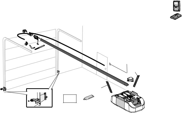
Carton Inventory
NOTE: Accessories will vary depending on the garage door opener model purchased. Depending on your specific model, other accessories may be included with your garage door opener. The instructions for these accessories will be attached to the accessory and are not included in this manual. The images throughout this manual are for reference and your product may look different.
A. Header bracket
B. Pulley and bracket
C. Door bracket
D. Curved door arm
E. Straight door arm
A
F. |
Trolley |
J. |
G. |
Emergency release rope and handle |
K. |
H. |
Rail |
L. |
I. |
Garage door opener |
M. |
|
|
N. |
B
Sprocket cover with hex screws
Belt
Door control
White and red/white wire
The Protector System®
Safety reversing sensors
with white and white/black wire attached:
Sending Sensor (1) Receiving Sensor (1)
and Safety Sensor Brackets (2)
C |
F |
K |
O. |
Safety labels and literature |
|
|
G |
P. |
Rail grease |
D |
|
|
||
|
|
|
|
E
H
L
M
Not Provided
J
|
Not Provided |
|
N |
P |
|
O |
||
|
I
SECURITY 2.0TM ACCESSORIES
882LM
Multi-Function Door Control
893LM
Remote Control
Hardware
Installation
Hex Bolt 5/16"-18 x 7/8" (4)
Lag Screw 5/16"-9 x 1-5/8" (2)
Clevis Pin 5/16" x 2-3/4" (1)
Clevis Pin 5/16" x 1-1/4" (1)
Clevis Pin 5/16" x 1" (1)
Nut 5/16"-18 (4)
Lock Washer 5/16" (4)
Self-Threading Screw 1/4"-14 x 5/8" (2)
Ring Fastener (3)
Carriage Bolt 1/4"-20 x 1/2" (2)
Wing Nut 1/4"-20 (2)
Door Control Hardware
Screw 6AB x 1" (2)
Screw 6-32 x 1" (2)
Drywall Anchors (2)
Insulated Staples
3

Assembly
1 Attach the rail to the garage door opener
To avoid possible SERIOUS INJURY to finger from moving garage door opener:
•ALWAYS keep hand clear ofsprocketwhile operating opener.
•Securelyattach sprocketcover BEFORE operating.
To avoid SERIOUS damage to garage door opener,use ONLY those bolts/fasteners mounted in the top ofthe opener.
HARDWARE
Washered Bolt 5/16"-18x1/2" (Mounted in the garage door opener)
Lock Nut (Mounted in the
garage door opener)
Hex Screw #8x3/8"
(Packed with the sprocket cover)
NOTE: ONLY use the boltsremoved fromthe garage door opener.Place the garage door opener on the packing material to prevent scratching.
1.1Remove boltand locknutfromthe top ofthe garage door opener.
1.2Align the rail and the styrofoamover the sprocket.Cutthe tape fromthe rail,belt, and styrofoam.
1.3Fasten the rail with the previously removed bolts.
Fasten the rail with the previously removed washer boltand locknut.
1.4Position the beltaround the garage door opener sprocket.
1.5Attach the sprocketcover over the garage door opener sprocketand attach with hexscrews.
HEX SCREW
W B #8X3/8"
ASHERED OLT
5/16"-18X1/2" LOCK
NUT
4

2 Tighten the Belt
2.1 |
Byhand,thread the spring trolleynuton the threaded shaftuntil itisfinger tightagainst 2.2 Inserta flathead screwdriver tip into one ofthe nutring slotsand brace itfirmlyagainstthe trolley. |
|
|
the trolley.Do notuse anytools. |
|
|
|
(To motor unit) |
|
Spring Trolley Nut |
Nut ring |
|
slot |
|
|
|
|
2.3Tighten the spring trolleynutwith an adjustable wrench or a 7/16" open end wrench abouta quarter turn until the spring releasesand snapsthe nutring againstthe trolley.Thissetsthe spring to optimumbelttension.
Nut Ring |
Nut Ring |
|
BEFORE |
|
|
|
|
AFTER RELEASE |
|||||
|
|
|
|||||||||
|
|
1" |
|
|
|
|
|
|
1-1/4" |
|
|
|
|
|
|
|
|||||||
|
(2.5 cm) |
|
|
|
|
|
(3.18 cm) |
||||
5

Installation
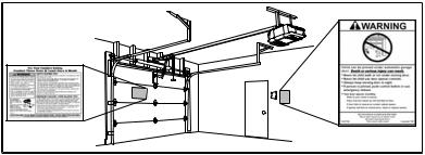
IMPORTANT INSTALLATION INSTRUCTIONS

 WARNING
To reduce the risk of SEVERE INJURY or DEATH:
1.READANDFOLLOWALL INSTALLATIONWARNINGS ANDINSTRUCTIONS.
2.Install garage door opener ONLY on properlybalanced and lubricated garage door.An improperlybalanced door mayNOTreverse when required and could resultin SEVERE INJURY or DEATH.
3.ALL repairsto cables,spring assembliesand other hardware MUSTbe made bya trained door systemstechnician BEFORE installing opener.
4.Disable ALL locksand remove ALL ropesconnected to garage door BEFORE installing opener to avoid entanglement.
5.Install garage door opener 7 feet(2.13 m) or more above floor.
6.Mountthe emergencyrelease within reach,butatleast6 feet(1.83 m) above the floor and avoiding contactwith vehiclesto avoid accidental release.
7.NEVERconnectgarage door opener to power source until instructed to do so.
8.NEVERwear watches,ringsor loose clothing while installing or servicing opener.Theycould be caughtin garage door or opener mechanisms.
9.Install wall-mounted garage door control:
•within sightofthe garage door.
•outofreach ofchildren atminimumheightof5 feet(1.5 m).
•awayfromALL moving partsofthe door.
10.Place entrapmentwarning label on wall nextto garage door control.
11.Place manual release/safetyreverse testlabel in plain viewon inside ofgarage door.
12.Upon completion ofinstallation,testsafetyreversal system.Door MUSTreverse on contactwith a 1-1/2"(3.8 cm) high object(or a 2x4 laid flat) on the floor.
13.To avoid SERIOUS PERSONAL INJURY or DEATHfromelectrocution,disconnectALL electricand batterypower BEFORE performing ANY service or maintenance.
14.DO NOTenable the Timer-to-Close functionalityifoperating either one-piece or swinging garage doors.To be enabled ONLY when operating a sectional door.
NOTE: Ifyouareinstallingthegaragedooropeneronaone-piecedoor,visitwww.liftmaster.comforinstallationinstructions.
6

1 Determine the header bracket location
To preventpossible SERIOUS INJURY or DEATH:
•Header bracketMUSTbe RIGIDLY fastened to structural supporton header wall or ceiling,otherwise garage door might NOTreverse when required.DO NOT install header bracketover drywall.
•Concrete anchorsMUSTbe used if mounting header bracketor 2x4 into masonry.
•NEVERtryto loosen,move or adjust garage door,springs,cables,pulleys, brackets,or their hardware,ALL ofwhich are under EXTREME tension.
•ALWAYS call a trained door systems technician ifgarage door binds,sticks,or is outofbalance.An unbalanced garage door mightNOTreverse when required.
•DO NOTenable the Timer-to-Close functionalityifoperating either one-piece or swinging garage doors.To be enabled ONLY when operating a sectional door.
NOTE: Ifyou are installing the garage door opener on a one-piece door,visitwww.liftmaster.comfor installation instructions.
1.1Close the door and markthe inside vertical centerline ofthe garage door.
1.2Extend the line onto the header wall above the door.
Youcanfastenthe headerbracket within4 feet (1.22 m) of the left orright of the door centeronly if a torsionspringorcenterbearingplate is inthe way; oryoucanattachit to the ceilingwhenclearance is minimal.(It may be mountedonthe wallupside downif necessary,togainapproximately 1/2" (1 cm).
Ifyou need to install the header bracketon a 2x4 (on wall or ceiling),use lag screws(not provided) to securelyfasten the 2x4 to structural supports.
1.3Open your door to the highestpointoftravel asshown.Drawan intersecting horizontal line on the header wall 2" (5 cm) above the high point.Thisheightwill provide travel clearance for the top edge ofthe door.
NOTE: Ifthe total number ofinchesexceedsthe heightavailable in your garage,use the maximum heightpossible,or refer to page 8 for ceiling installation.
Header Wall
2" (5 cm)
Track
Highest Point
of Travel
 Door
Door
Unfinished |
OPTIONAL |
|
CEILING |
||
Ceiling |
||
MOUNT FOR |
||
|
||
Header Wall |
HEADER |
|
BRACKET |
||
|
||
2x4 |
|
|
Vertical Centerline |
|
|
of Garage Door |
|
|
2x4 |
Structural |
|
|
Supports |
|
Level |
|
|
(Optional) |
|
SECTIONAL DOOR WITH CURVED TRACK
7
Installation
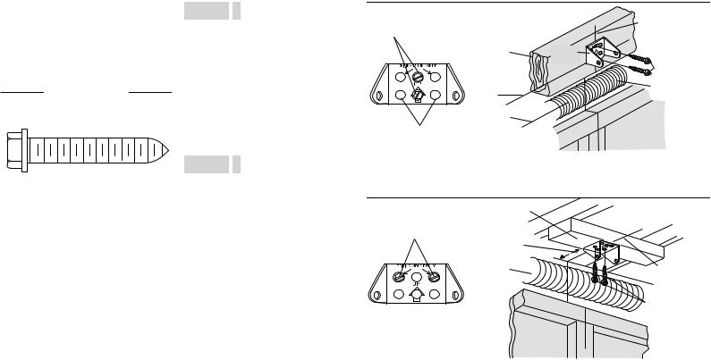
2 Install the Header Bracket
You can attach the header bracketeither to the wall above the garage door,or to the ceiling. Followthe instructionswhich will workbestfor your particular requirements.Donot installthe headerbracket overdrywall.If installinginto masonry,use concrete anchors (not provided).
HARDWARE
LAG SCREW
5/16" - 9 X 1-5/8"
OPTION A WALL INSTALLATION
2.1A Center the bracketon the vertical centerline with the bottomedge ofthe bracketon the horizontal line asshown (with the arrowpointing toward the ceiling).
2.2A Markthe vertical setofbracketholes(do notuse the holesdesignated for ceiling mount).Drill 3/16" pilotholesand fasten the bracketsecurelyto a structural supportwith lag screws.
OPTION B CEILING INSTALLATION
2.1B Extend the vertical centerline onto the ceiling asshown.
2.2B Center the bracketon the vertical mark, no more than 6" (15 cm) fromthe wall. Make sure the arrowispointing toward the wall.The bracketcan be mounted flush againstthe ceiling when clearance isminimal.
2.3B Markthe side holes.Drill 3/16" pilotholes and fasten bracketsecurelyto a structural supportwith lag screws.
|
|
(Header Wall) |
Vertical |
|
|
|
|
Wall Mount |
|
|
Centerline of |
|
|
Garage Door |
|
|
|
|
|
|
2x4 Structural |
|
|
|
Support |
Header |
|
|
|
Bracket |
|
|
|
|
Lag Screw |
|
|
|
5/16" - 9 x 1-5/8" |
|
Horizontal |
|
Door Spring |
|
Line |
|
|
|
|
|
|
|
Highest Point of |
|
|
|
Garage Door |
|
|
Optional |
Travel |
|
(Garage Door) |
Mounting |
|
|
|
Holes |
|
|
|
Header
Bracket |
(Finished Ceiling) |
|
|
Ceiling Mounting Holes |
|
6" (15 cm) |
|
Maximum |
|
Door Spring |
Vertical |
|
|
|
Centerline of |
|
Garage Door |
|
Lag Screw |
|
5/16" - 9 x 1-5/8" |
(Garage Door) |
(Header Wall) |
|
8
3 Attach the rail to the header bracket |
|
|
3.1 Align the rail with the header bracket. |
Ring |
|
Insertthe clevispin through the holesin |
||
Fastener |
||
the header bracketand rail.Secure |
|
|
with the ring fastener. |
|
|
NOTE: Use the packing material asa |
Clevis Pin |
|
5/16" X 2-3/4" |
||
protective base for the garage door opener. |
||
|
HARDWARE
|
|
|
|
|
|
|
|
|
|
|
|
|
|
|
|
|
|
|
|
|
|
|
|
|
|
|
Clevis Pin |
Ring Fastener |
|
|
|
5/16" x 2-3/4" |
||
|
|
|
|
|
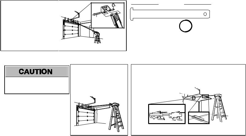
4 Position the garage door opener
To preventdamage to garage door,restgarage door opener rail on 2x4 placed on top section of door.
4.1Remove the packing material and liftthe garage door opener onto a ladder.
NOTE: A 2x4 isideal for setting the distance between the rail and the door.Ifthe ladder is nottall enough you will need help atthispoint.
4.2Fullyopen the door and place a 2x4 (laid flat) under the rail.
NOTE: Ifthe door hitsthe trolleywhen itisraised,pull the trolleyrelease armdown to disconnectthe inner and outer trolley.Slide the outer trolleytoward the garage door opener. The trolleycan remain disconnected until instructed.
CONNECTED DISCONNECTED
9

Installation
5 Hang the garage door opener
To avoid possible SERIOUS INJURY froma falling garage door opener,fasten itSECURELY to structural supportsofthe garage.Concrete anchors MUSTbe used ifinstalling ANY bracketsinto masonry.
HARDWARE
LOCK WASHER
5/16"
HEX BOLT 5/16"- 18X7/8"
NUT 5/16"-18
Hanging your garage door opener will varydepending on your garage.Two representative installationsare shown.Yoursmay be different.Hanging bracketsshould be angled (Figure 1) to provide rigid support.On finished ceilings(Figure 2),attach a sturdymetal bracketto structural supportsbefore installing the opener.Thisbracketand fastening hardware are notprovided. Instructionsbeloware for attaching the garage door opener directlyto structural supports.
5.1Measure the distance fromeach side ofthe motor unitto the structural support.
5.2Cutboth piecesofthe hanging bracketto required lengths.
5.3Drill 3/16" pilotholesin the structural supports.
5.4Attach one end ofeach bracketto a supportwith 5/16"- 18x1-7/8" lag screws(notprovided).
5.5Fasten the opener to the hanging bracketswith 5/16"- 18x7/8" hexbolts,lockwashersand nuts.
5.6Checkto make sure the rail iscentered over the door (or in line with the header bracketifthe bracketisnotcentered above the door).
5.7Remove the 2x4.Operate the door manually.Ifthe door hitsthe rail,raise the header bracket.
NOTE: DO NOTconnectpower to opener atthistime.
FIGURE 1
Unfinished Ceiling
FIGURE 3
Measure
Distance
FIGURE 2
Finished Ceiling
Not Provided
(Not Provided) Lag Screws 5/16"- 18x1-7/8"
Hex Bolt 5/16"- 18x7/8", Lock Washer 5/16", Nut 5/16"-18
10
6 Install the light bulbs
To preventpossible OVERHEATING ofthe end panel or lightsocket:
•Use ONLY A19 incandescent(100W maximum) or compactfluorescent(26W maximum) light bulbs.
•DO NOTuse incandescentbulbslarger than 100W.
•DO NOTuse compactfluorescentlightbulbslarger than 26W(100Wequivalent).
•DO NOTuse halogen bulbs.
•DO NOTuse shortneckor specialtylightbulbs.
6.1Pull on the top center ofthe lightlensand rotate the lightlensdown.
6.2Insertan A19 incandescent(100Wmaximum) or compactfluorescent(26W,100W equivalent) light bulb into the lightsocket.
NOTE: Do notuse halogen,shortneck,or specialtylight bulbsasthese mayoverheatthe end panel or lightsocket. Do notuse LEDbulbsastheymayreduce the range or performance ofyour remote control(s).
6.3 Rotate the lensup to close.
OR |
OR |
7 Attach the emergency release rope and handle
To preventpossible SERIOUS INJURY or DEATHfroma falling garage door:
•Ifpossible,use emergencyrelease handle to disengage trolleyONLY when garage door is CLOSED.Weakor broken springsor unbalanced door could resultin an open door falling rapidlyand/or unexpectedly.
•NEVERuse emergencyrelease handle unlessgarage doorwayisclear ofpersonsand obstructions.
•NEVERuse handle to pull door open or closed.Ifrope knotbecomesuntied,you could fall.
7.1Insertone end ofthe emergencyrelease rope through the handle.Make sure that“NOTICE” is rightside up.Tie a knotatleast1 inch (2.5 cm) from the end ofthe emergencyrelease rope.
7.2Insertthe other end ofthe emergencyrelease rope through the hole in the trolleyrelease arm.Mount the emergencyrelease within reach,butatleast6 feet(1.83 m) above the floor,avoiding contactwith vehiclesto preventaccidental release and secure with a knot.
NOTE: Ifitisnecessaryto cutthe emergencyrelease rope, seal the cutend with a match or lighter to prevent unraveling.Ensure the emergencyrelease rope and handle are above the top ofall vehiclesto avoid entanglement.
Trolley |
Release Arm |
11
Installation
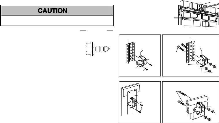
8 Install the door bracket
Fiberglass,aluminumor lightweightsteel garage doorsWILLREQUIRE reinforcementBEFORE installation ofdoor bracket.Contactyour door manufacturer for reinforcementkit.
Figure 1 showsone piece ofangle iron asthe horizontal brace. For the vertical brace,2 piecesofangle iron are used to create a U-shaped support.The bestsolution isto checkwith your garage door manufacturer for an opener installation door reinforcement kit.
NOTE: Manydoor reinforcementkitsprovide for directattachment ofthe clevispin and door arm.In thiscase you will notneed the door bracket;proceed to the nextstep.
SECTIONALDOORS
HARDWARE
Self-Threading Screw
1/4"-14x5/8 "
8.1 Center the door bracketon the previouslymarked vertical centerline used for the header bracket installation.Note correctUP placement,asstamped inside the bracket.
8.2Position the top edge ofthe bracket2"-4" (5-10 cm) belowthe top edge ofthe door,ORdirectlybelow anystructural supportacrossthe top ofthe door.
8.3Mark,drill holesand install asfollows,depending on your door’sconstruction:
Metalorlight weight doors usinga verticalangle ironbrace betweenthe doorpanelsupport andthe doorbracket:
• Drill 3/16" fastening holes.Secure the door bracketusing the two selfthreading screws. (Figure 2)
• Alternately,use two 5/16" bolts,lockwashersand nuts(notprovided).(Figure 3)
Metal,insulatedorlight weight factory reinforceddoors:
• Drill 3/16" fastening holes.Secure the door bracketusing the self-threading screws.(Figure 4)
WoodDoors:
• Use top and bottomor side to side door bracketholes.Drill 5/16” holesthrough the door and secure bracketwith 5/16"-18x2" carriage bolts,lockwashersand nuts(notprovided).(Figure 5)
NOTE: The 1/4"-14x5/8"self-threading screwsare notintended for use on wood doors.
FIGURE 1
A horizontal and vertical reinforcement is needed for lightweight garage doors (fiberglass, aluminum, steel, doors with glass panel, etc.) (not provided).
A horizontal reinforcement brace should be long enough to be secured to two or three vertical supports.
A vertical reinforcement brace should cover the height of the top panel.
FIGURE 2
Vertical Reinforcement
Vertical Centerline
of Garage Door
UP
Door Bracket
Self-Threading Screw 1/4" - 14x 5/8"
FIGURE 4
Vertical Centerline
of Garage Door
UP
Self-Threading Screw
1/4" - 14x 5/8"
FIGURE 3
Vertical Reinforcement
Vertical Centerline
of Garage Door
Bolt 5/16"-18x2"
(Not provided)
UP
Door Bracket
Lock Washer 5/16"
Nut 5/16"-18
FIGURE 5
Bolt 5/16"-18x2"
(Not provided) Inside Edge of Door or Reinforcement Board
UP
Vertical
Centerline of
Garage Door
12
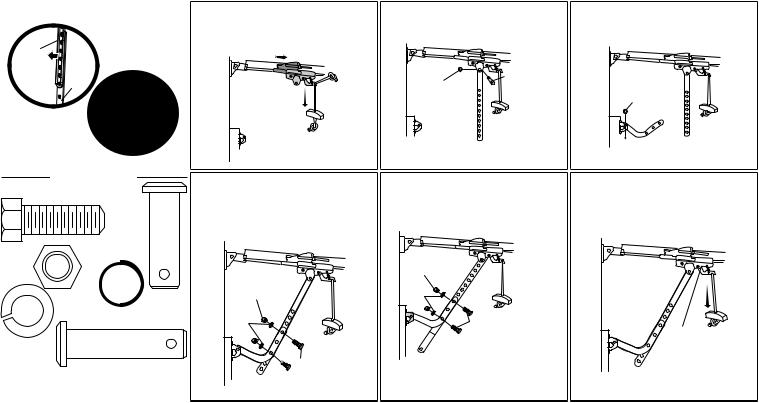
9 Connect the door arm to the trolley
IMPORTANT: The groove on the straightdoor armMUSTface awayfromthe curved door arm.
CORRECT |
|
|
Straight |
|
|
Door Arm |
Curved |
INCORRECT |
|
||
(Groove |
Door |
|
facing out) |
Arm |
|
Straight |
|
Door |
|
Arm |
Curved |
|
|
|
Door |
|
Arm |
9.1Close the door.Disconnectthe trolleyby pulling the emergencyrelease handle. Slide the outer trolleyback(awayfrom the door) about2" (5 cm).
9.2Attach the straightdoor armto the outer trolleyusing the clevispin.Attach with the ring fastener.
|
Clevis Pin |
Ring |
5/16" x 1" |
|
|
Fastener |
|
9.3Attach the curved door armto the door bracketusing the clevispin.Attach with the ring fastener.
Ring
Fastener

 Clevis Pin
5/16 " x 1-1/4"
HARDWARE
Hex Bolt 5/16"-18x7/8"
Clevis Pin 5/16"x1"
Nut 5/16"-18
|
Ring Fastener |
Lock |
|
Washer |
|
5/16" |
Clevis Pin 5/16"x1-1/4" |
9.4Align the straightdoor armwith the curved door arm.Selecttwo aligned holes(asfar apartaspossible) and attach using the bolts,nutsand lock washers.
NUT 5/16" - 18
LOCK
WASHER 5/16"

 HEX BOLT
5/16" - 18 X 7/8"
NOTE: Ifthe holesdo notline up,reverse the straightdoor arm.Selecttwo aligned holes(as far apartaspossible) and attach using the bolts,nutsand lockwashers.
9.5Pull the emergencyrelease handle toward the garage door opener until the trolleyrelease armishorizontal.The trolleywill re-engage automaticallywhen the garage door opener isactivated.
Nut 5/16" - 18
Lock Washer 5/16"
Hex Bolt |
|
|
5/16" - 18 x 7/8" |
Trolley |
|
If the straight door arm is hanging |
||
release arm |
||
down too far, you may cut 6 inches |
||
|
||
(15 cm) from the solid end. |
|
13

Install the Door Control
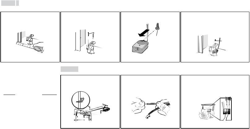
1 Install the door control
To preventpossible SERIOUS INJURY or DEATHfromelectrocution:
•Be sure power isNOTconnected BEFORE installing door control.
•ConnectONLY to 12 VOLTlowvoltage wires.
To preventpossible SERIOUS INJURY or DEATHfroma closing garage door:
•Install door control within sightofgarage door,outofreach ofchildren ata minimumheightof5 feet (1.5 m),and awayfromALL moving partsofdoor.
•NEVERpermitchildren to operate or playwith door control push buttonsor remote control transmitters.
•Activate door ONLY when itcan be seen clearly,isproperlyadjusted,and there are no obstructionsto door travel.
•ALWAYS keep garage door in sightuntil completelyclosed.NEVERpermitanyone to crosspath of closing garage door.
INTRODUCTION
Compatible with MyQ® and Security+2.0™ accessories,see page 37.Your garage door opener iscompatible with up to 2 SmartControl Panelsor 4 ofanyother Security+2.0™ door controls.NOTE: OlderLiftMasterdoorcontrols andthirdpartyproductsarenotcompatible.
Install the door control within sightofthe door at a minimumheightof5 feet(1.5 m) where small children cannotreach,and awayfromthe moving partsofthe door.
NOTE: Yourproductmaylookdifferentthan movingpartsofthedoortheillustrations.
NOTE: Forgangboxinstallationsitisnotnecessarytodrillholesorinstallthedrywallanchors.Usetheexistingholesinthegangbox.
1.1Strip 7/16 inch (11 mm) ofinsulation from one end ofthe wire and separate the wires.
7/16" (11 MM)
1.2Connectone wire to each ofthe two screws on the backofthe door control.The wires can be connected to either screw.
PRE-WIREDINSTALLATIONS: Choose anytwo wiresto connect,note which wires are used so the correctwiresare connected atthe garage door opener in a later step.
1.3Markthe location ofthe bottommounting hole and drill a 5/32 inch (4 mm) hole.
WALL
HARDWARE
Screw 6ABx1"
 Drywall Screw
  Anchors 6-32x1"
1.4Install the bottomscrew,allowing 1/8 inch (3 mm) to protrude fromthe wall.
DRYWALL |
GANG BOX |
|
|
Drywall Anchor |
Screw |
|
|
Screw |
6-32 x 1" |
|
|
6AB x 1" |
|
14

Install the Door Control
1.5 Position the bottomhole ofthe door 1.6 Liftthe push bar up and markthe top hole. control over the screwand slide
down into place.
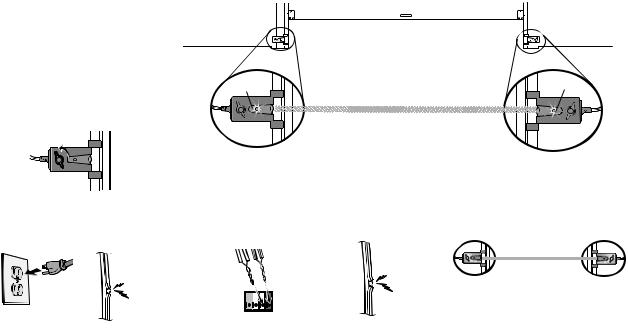
2 Wire the door control to the garage door opener
HARDWARE
Insulated Staple (Not shown)
PRE-WIREDINSTALLATIONS: When wiring the door control to the garage door opener make sure you use the same wiresthatare connected to the door control.
2.1Run the white and red/white wire fromthe door control to the garage door opener.Attach the wire to the wall and ceiling with the staples(notapplicable for gang boxor pre-wired installations).Do notpierce the wire with the staple asthismaycause a shortor an open circuit.
Staple
1.7Remove the door control fromthe wall and drill a 5/32 inch (4 mm) hole for the top screw.
2.2Strip 7/16 inch (11 mm) ofinsulation fromthe end ofthe wire near the garage door opener.
7/16" (11 MM)
1.8Position the bottomhole ofthe door control over the screwand slide down into place.Attach the top screw.
DRYWALL
Drywall Anchor

 Screw
Screw 


 6AB x 1"
Screw  6-32 x 1"
GANG BOX
2.3Connectthe wire to the red and white terminalson the garage door opener.To insertor release wiresfromthe terminal, push in the tab with screwdriver tip.
RED |
WHITE |
WHITE |
GREY |
|
|
|
|
|
|
|
|
|
|
|
|
|
|
|
|
15
Install the Door Control
3 Attach the warning labels
3.1Attach the entrapmentwarning label on the wall near the door control with tacksor staples.
3.2Attach the manual release/safetyreverse testlabel in a visible location on the inside of the garage door.
16

Install the Protector System®
Introduction
Be sure power isNOTconnected to the garage door opener BEFORE installing the safety reversing sensor.
To preventSERIOUS INJURY or DEATHfrom closing garage door:
•Correctlyconnectand align the safety reversing sensor.Thisrequired safety device MUSTNOTbe disabled.
•Install the safetyreversing sensor so beam isNO HIGHERthan 6" (15 cm) above garage floor.
IMPORTANTINFORMATIONABOUTTHE SAFETY REVERSING SENSORS
The safety reversingsensors must be connectedandalignedcorrectly before the garage dooropenerwillmove inthe downdirection.
The sending sensor (with an amber LED) transmitsan invisible lightbeamto the receiving sensor (with a green LED).Ifan obstruction breaksthe light beamwhile the door isclosing,the door will stop and reverse to the full open position,and the garage door opener lightswill flash 10 times.
NOTE: For energyefficiencythe garage door opener will enter sleep mode when the door isfullyclosed.The sleep mode shutsthe garage door opener down until activated.The sleep mode issequenced with the garage door opener lightbulb;asthe lightbulb turnsoffthe sensor LEDswill turn offand whenever the garage door opener lightsturn on the sensor LEDswill light.The garage door opener will notgo into the sleep mode until the garage door opener hascompleted 5 cyclesupon power up.
Wheninstallingthe safety reversingsensors check the following:
•Sensorsare installed inside the garage,one on either side ofthe door.
•Sensorsare facing each other with the lensesaligned and the receiving sensor lensdoesnotreceive directsunlight.
•Sensorsare no more than 6 inches(15 cm) above the floor and the lightbeamisunobstructed.
Safety Reversing Sensor |
Invisible Light Beam |
Safety Reversing Sensor |
|
6" (15 cm) max. above floor |
|||
6" (15 cm) max. above floor |
|||
|
Protection Area |
||
|
|
17

Install the Protector System®
1 Install the Safety Reversing Sensors
The safetyreversing sensorscan be attached to the door track,the wall,or the floor.Ifthe door trackwill notsupportthe sensor bracketa wall installation isrecommended.Choose one ofthe following installations.
HARDWARE
Carriage Bolt 1/4"-20x1/2"
Wing Nut 1/4"-20
OPTION B WALL INSTALLATION
OPTION A DOOR TRACK INSTALLATION
1.1A Slide the curved armsofthe sensor |
1.2A Slide the carriage boltinto the sloton |
1.3A Insertthe boltthrough the hole in the sensor |
||
bracketaround the edge ofthe door |
each sensor. |
bracketand attach with the wing nut.The lenses |
||
track.Snap into place so thatthe |
|
on both sensorsshould pointtoward each other. |
||
sensor bracketisflush againstthe |
|
Make sure the lensisnotobstructed bythe |
||
track. |
|
|||
|
sensor bracket. |
|||
|
|
|
||
|
|
|
Wing Nut |
|
|
|
|
|
|
|
|
|
|
|
|
|
|
1/4" - 20 |
|
Carriage Bolt  1/4" - 20 x 1/2"
Ifadditional clearance isneeded an extension bracket(notprovided) or wood blockscan be used.Make sure each brackethasthe same amountofclearance so theywill align correctly.
1.1B Position the sensor bracketagainstthe |
1.2B Drill 3/16 inch pilotholesfor each sensor 1.3B |
Slide the carriage boltinto the sloton |
1.4B Insertthe boltthrough the hole in the sensor |
||||||||||
wall with the curved armsfacing the |
bracketand attach the sensor brackets |
each sensor. |
bracketand attach with the wing nut.The lenses |
||||||||||
door.Make sure there isenough |
to the wall using lag screws(not |
|
on both sensorsshould pointtoward each |
||||||||||
clearance for the beamto be |
provided). |
|
|
other.Make sure the lensisnotobstructed by |
|||||||||
unobstructed.Markholes. |
|
|
|
|
|
the sensor bracket. |
|||||||
|
|
Inside |
|
|
|
||||||||
|
|
|
|
|
|
rage |
|
|
|
|
|
|
|
|
|
|
|
|
|
Ga |
|
|
|
|
|
|
|
|
|
|
|
|
|
l |
|
|
|
|
|
|
Wing Nut |
|
|
|
(not provided) |
|
|
Wal |
|
(not provided) |
Carriage Bolt |
|
|
|
|
|
|
|
|
|
|
|
|
|
|
|
|||
|
|
|
|
|
|
|
|
|
|
|
|||
|
|
|
|
|
|
|
Lens |
|
|
1/4" - 20 |
|||
|
|
|
|
|
|
|
|||||||
|
|
|
|
|
|
|
|||||||
|
|
|
|
|
|
|
|
1/4" - 20 x 1/2" |
|
|
|
|
|
|
|
|
|
|
|
|
|
|
|
|
|
|
|
|
|
|
|
|
|
|
|
|
|
|
|
|
|
|
|
|
|
|
|
|
|
|
|
|
|
|
|
18
Install the Protector System®
1 Install the Safety Reversing Sensors
OPTION C FLOOR INSTALLATION
Use an extension bracket(notprovided) or wood blockto raise the sensor bracketifneeded.
1.1C Carefullymeasure the position ofboth |
1.2C Attach the sensor bracketsto the floor |
1.3C Slide the carriage boltinto the sloton |
1.4C Insertthe boltthrough the hole in the sensor |
sensor bracketsso theywill be the same |
using concrete anchors(not |
each sensor. |
bracketand attach with the wing nut.The lens |
distance fromthe wall and unobstructed. |
|
on both sensorsshould pointtoward each |
|
provided). |
|
||
|
|
other.Make sure the lensisnotobstructed by |
|
|
|
|
|
|
(not provided) |
|
the sensor bracket. |
de Insi Garage ll Wa
Carriage Bolt |
Wing Nut |
|
1/4" - 20 x 1/2" |
||
1/4" - 20 |
||
|
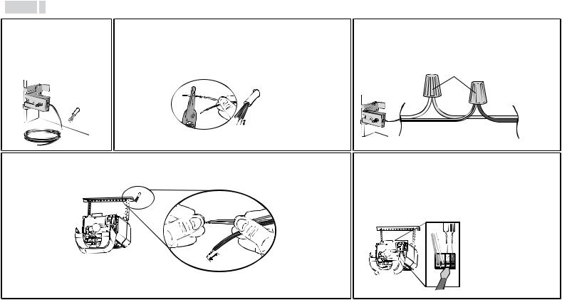
2 Wire the Safety Reversing
Sensors |
OPTION A INSTALLATION WITHOUT PRE-WIRING |
|
|
PRE-WIREDINSTALLATIONS: Ifyour garage |
2.1A Run the wire fromboth sensorsto the |
2.2A Strip 7/16 inch (11 mm) ofinsulation |
2.3A Insertthe white wiresinto the white terminal on |
alreadyhaswiresinstalled for the safetyreversing |
garage door opener.Attach the wire to |
fromeach setofwires.Separate the |
the garage door opener.Insertthe white/black |
sensors,see page 20. |
the wall and ceiling with the staples. |
wires.Twistthe white wirestogether. |
wiresinto the greyterminal on the garage door |
|
|
Twistthe white/blackwirestogether. |
opener.To insertor remove the wiresfromthe |
HARDWARE |
Staple |
|
terminal,push in the tab with a screwdriver tip. |
|
|
|
|
Insulated Staple |
|
|
WHITE GYRE |
(Not shown) |
|
|
|
|
|
|
|
|
|
7/16" |
|
|
|
(11 MM) |
|
19
Install the Protector System®
OPTION B PRE-WIRED INSTALLATION
2.1B Cutthe end ofthe safety |
2.2B Separate the safetyreversing sensor wiresand strip 7/16 inch (11 mm) of |
||
reversing sensor wire,making |
insulation fromeach end.Choose two ofthe pre-installed wiresand strip 7/16 |
||
sure there isenough wire to |
inch (11 mm) ofinsulation fromeach end.Make sure thatyou choose the |
||
reach the pre-installed wires |
same color pre-installed wiresfor each sensor. |
||
fromthe wall. |
|
|
|
|
|
Safety reversing sensor wires |
|
|
|
7/16" |
Pre-installed |
|
|
wires |
|
|
|
(11 mm) |
|
|
|
|
|
|
|
|
7/16" |
|
|
|
(11 mm) |
2.3B Connectthe pre-installed wiresto the sensor wireswith wire nuts making sure the colorscorrespond for each sensor.For example, the white wire would connectto the yellowwire and the white/black wire would connectto the purple wire.
|
Not Provided |
|
|
Yellow |
|
White |
(for example) |
|
|
|
Pre-installed |
|
|
wires |
|
White/Black |
Purple |
|
|
(for example) |
Safety reversing sensor wires
2.4B Atthe garage door opener,strip 7/16 inch (11 mm) ofinsulation fromeach end ofthe wirespreviouslychosen for the |
2.5B Insertthe wiresconnected to the white safetysensor wiresto the |
safetyreversing sensors.Twistthe like-colored wirestogether. |
white terminal on the garage door opener.Insertthe wiresthatare |
|
connected to the white/blacksafetysensor wiresto the grey |
|
terminal on the garage door opener. |
Yellow |
Yellow |
|
(for example) |
||
|
||
Purple |
|
|
7/16" |
|
|
(11 mm) |
|
|
|
||
|
Purple
(for example)
WHITE |
GREY |
To insert or remove the wires from the terminal, push in the tab with a screwdriver tip.
20
Power
1 Connect Power
To prevent possible SERIOUS INJURY or DEATH from electrocution or fire:
•Be sure power is NOT connected to the opener, and disconnect power to circuit BEFORE removing cover to establish permanent wiring connection.
•Garage door installation and wiring MUST be in compliance with ALL local electrical and building codes.
•NEVER use an extension cord, 2-wire adapter, or change plug in any way to make it fit outlet. Be sure the opener is grounded.
To avoid installation difficulties, do not activate the garage door opener at this time.
To reduce the risk of electric shock, your garage door opener has a grounding type plug with a third grounding pin. This plug will only fit into a grounding type outlet. If the plug doesn’t fit into your outlet, contact a qualified electrician to install the proper outlet.
THERE ARE TWO OPTIONS FORCONNECTING POWER:
OPTION A TYPICAL WIRING
1.1A Plug in the garage door opener into a grounded outlet. 1.2A DO NOT run garage door opener at this time.
OPTION B PERMANENT WIRING
If permanent wiring is required by your local code, refer to the following procedure.
To make a permanent connection through the 7/8 inch hole in the top of the motor unit (according to local code):
1.1B Remove the motor unit cover screws and set the cover aside.
1.2B Remove the attached 3-prong cord.
1.3B Connect the black (line) wire to the screw on the brass terminal; the white (neutral) wire to the screw on the silver terminal; and the ground wire to the green ground screw. The opener must be grounded.
1.4B Reinstall the cover.
TYPICAL WIRING
PERMANENT WIRING
GROUND TAB

GREEN
GROUND
SCREW
GROUND
WIRE
WHITE WIRE
BLACK
WIRE
BLACK
WIRE
21
Power
2 Ensure the Safety Reversing Sensors are aligned
The doorwillnot close if the sensors |
2.1 Checkto make sure the LEDsin both sensorsare glowing steadily.The LEDsin both sensorswill glowsteadilyifthey |
|
have not beeninstalledandaligned |
are aligned and wired correctly. |
|
correctly. |
||
|
||
When the lightbeamisobstructed or |
|
|
misaligned while the door isclosing,the |
If the receiving sensor is in |
|
door will reverse and the garage door |
||
direct sunlight, switch it with |
||
opener lightswill flash ten times.Ifthe door |
sending sensor so it is on the |
|
isalreadyopen,itwill notclose.The |
opposite side of the door. |
sensorscan be aligned byloosening the |
Amber LED |
|
Green LED |
wing nuts,aligning the sensors,and |
|
|
(invisible light beam) |
tightening the wing nuts. |
|
|
|
|
|
|
|
|
|
SENDING SENSOR |
RECEIVING SENSOR |
IFTHE AMBERLEDONTHE SENDING SENSORIS NOTGLOWING: |
IFTHE GREENLEDONTHE RECEIVING SENSORIS NOTGLOWING: |
||
Make sure there is |
Make sure the |
power to the garage |
sensor wire is not |
door opener. |
shorted/broken. |
Make sure the sensor has been wired correctly: white wires to white terminal and white/black wires to grey terminal.
Make sure the sensor wire is not shorted/broken.
Make sure the sensors are aligned.
GREY
WHITE
WHITE
RED
3 Ensure the Door Control is wired correctly
Ifthe door control hasbeen installed and wired correctly,the command LEDbehind the push bar will blink.
22

Adjustments
Withouta properlyinstalled safetyreversal system,persons(particularlysmall children) could be SERIOUSLY INJUREDor KILLEDbya closing garage door.
•Incorrectadjustmentofgarage door travel limitswill interfere with proper operation of safetyreversal system.
•After ANY adjustmentsare made,the safety reversal systemMUSTbe tested.Door MUSTreverse on contactwith 1-1/2" (3.8 cm) high object(or 2x4 laid flat) on floor.
To preventdamage to vehicles,be sure fully open door providesadequate clearance.
INTRODUCTION
Your garage door opener isdesigned with electroniccontrolsto make setup and adjustmentseasy.The adjustmentsallowyou to programwhere the door will stop in the open (UP) and close (DOWN) position.The electroniccontrolssense the amountofforce required to open and close the door.The force isadjusted automaticallywhen you programthe travel.
NOTE: Ifanything interfereswith the door’s upward travel itwill stop.Ifanything interferes with the door’sdownward travel,itwill reverse.
To watch a shortinstructional video on programming your newgarage door opener use your smartphone to read the QRCode below:
PROGRAMMING BUTTONS
The programming buttonsare located on the leftside panel ofthe garage door opener and are used to programthe travel.
UP (Open) |
DOWN (Close) |
PROGRAMMING BUTTONS
UP Button
Adjustment
Button
DOWN Button
23
Loading...