


 Loading...
F A C T O R Y S E T
C2 Wiring
See page 6 for other wiring
configurations
OWNER'S MANUAL
MODEL EGJ
EUROPEAN GEARHEAD CARWASH JACKSHAFT
60126 .
PLACE |
RATING |
|
|
|
LABEL |
|
|
|
|
HERE |
|
|
|
|
|
41B6 |
|
LISTED |
DOOR |
|
|
OPERATOR |
|
|
|
|
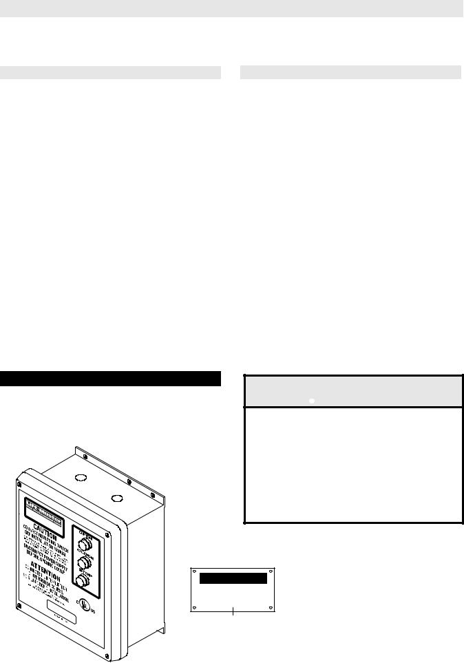
2 YEAR WARRANTY
Serial #
(located on electrical box cover)
Installation Date
Wiring Type
NOT FOR RESIDENTIAL USE
41B6
LISTED DOOR OPERATOR

SPECIFICATIONS
|
|
|
|
|
|
|
|
|
|
MOTOR |
|
|
ELECTRICAL |
||
|
TYPE: ................................. |
Gearhead Jackshaft. |
|
TRANSFORMER: |
............. |
24VAC |
|
|
HORSEPOWER: ................ |
1/2, 3/4 & 1 Hp |
|
......CONTROL STATION: NEMA 1 three button station. |
|
||
|
|
Single or Three phase |
|
|
OPEN/CLOSE/STOP |
|
|
|
SPEED:............................... |
1725 RPM |
|
WIRING TYPE:................. |
|
C2 (Standard) |
|
|
VOLTAGE: |
115 & 230 Single phase |
|
Momentary contact to OPEN/CLOSE/STOP plus wiring |
|
||
|
|
for sensing device to reverse and auxiliary devices to |
|
||||
|
|
230 & 460 Three phase |
|
|
|||
|
|
|
open and close with open override. |
|
|||
|
CURRENT: |
See motor nameplate |
|
|
|||
|
|
LIMIT ADJUST: |
|
Linear driven, fully |
|
||
|
|
|
|
|
|
||
|
|
|
|
adjustable screw type cams. Adjustable to 30 feet. |
|
||
|
|
|
|
BRAKE: |
|
Dynamic brake,provides |
|
|
|
|
|
||||
|
|
|
|
....................................... |
|
electrical braking in the form |
|
|
|
|
|
of DC current to stop the . |
motor. |
|
|
|
|
|
|
|
|
|
|
|
|
|
|
|
|
|
|
|
|
SAFETY |
|
MECHANICAL |
|
||
DRIVE REDUCTION:............. |
45:1 Reduction |
DISCONNECT:.............. |
Floor level clutch disconnect with |
|
Hollow Shaft Gear. |
electrical interlock for emergency manual door operation |
|
OUTPUT SHAFT SPEED:..... |
39 R.P.M. |
CLUTCH: ...................... |
Adjustable Slipping Clutch |
DOOR SPEED:...................... |
4 - 10" per sec. |
REVERSING EDGE: .... |
(Optional) Electric or pneumatic |
|
depending on door |
sensing device attached to the bottom edge of door. |
|
CLUTCH: ............................... |
Slipping Clutch |
A REVERSING EDGE IS STRONGLY RECOMMEND- |
|
|
|
ED FOR ALL COMMERCIAL OPERATOR INSTALLA- |
|
TIONS. REQUIRED WHEN THE 3 BUTTON CON-
TROL STATION IS OUT OF SIGHT OF DOOR OR
ANY OTHER CONTROL (AUTOMATIC OR MANUAL)
IS USED.
EGJ DIMENSIONS
See Chart
|
|
|
|
|
|
|
|
|
|
|
|
|
|
|
|
|
|
8.43” |
|
|
|
|
|
|
|
|
|
|
|
|
|
|
|
|
|
9.13” |
||
|
|
|
|
|
|
|
|
|
|
|
||
|
|
|
|
|
|
|
|
|
|
|
|
|
|
|
|
|
|
|
|
|
|
|
|
|
|
|
|
3.30” |
|
|
|
|
|
|
|
|
||
|
|
|
|
|
|
|
3.94” |
|
|
|
||
|
|
|
|
|
|
|
|
|
|
|
||
|
|
|
|
|
|
|
|
|
|
|
|
|
|
|
|
|
|
|
|
|
|
|
|
|
|
9.92”
4.73” 
 2.76”
2.76”
|
3.86” |
|
|
HP |
PHASE |
DIMENSION |
|
2.61” |
.630 DIA. HOLE |
1/2 |
1 |
21” |
|
1.36” |
|
3/4 |
1 |
22” |
||
|
(4 PLACES) |
|||||
|
|
|
|
1 |
1 |
23-5/16” |
|
|
5.23” |
5.75” |
1/2 |
3 |
21-1/8” |
|
|
3/4 |
3 |
22” |
||
|
|
|
|
|||
MOUNTING DIMENSIONS |
1 |
3 |
23-1/2” |
|||
2

IMPORTANT SAFETY NOTES
 CAUTION
TO AVOID DAMAGE TO DOOR AND OPERATOR, MAKE ALL DOOR LOCKS INOPERATIVE. SECURE LOCK(S) IN "OPEN" POSITION.
IF THE DOOR LOCK NEEDS TO REMAIN FUNCTIONAL, INSTALL AN INTERLOCK SWITCH.
DO NOT CONNECT ELECTRIC POWER UNTIL INSTRUCTED TO DO SO.
 WARNING
KEEP DOOR BALANCED. STICKING OR BINDING DOORS MUST BE REPAIRED. DOORS, DOOR SPRINGS, CABLES, PULLEYS, BRACKETS AND THEIR HARDWARE MAY BE UNDER EXTREME TENSION AND CAN CAUSE SERIOUS PERSONAL INJURY. CALL A PROFESSIONAL DOOR SERVICEMAN TO MOVE OR ADJUST DOOR SPRINGS OR HARDWARE.
SITE PREPARATIONS
It is imperative that the wall or mounting surface provide adequate support for the operator. The safety and wear of the operator will be adversely affected if any of the following requirements are not met.
a)Be rigid to prevent play between operator and door shaft.
b)Provide a level base.
c)Permit the operator to be fastened securely and with the drive shaft parallel to the door shaft.
INSTALLATION INSTRUCTIONS
TYPICAL HOLLOW SHAFT INSTALLATION
1.Slide the shaft collar supplied over the door shaft to desired position and secure in place.
2.Slide the operator on the door shaft until it is laying against the shaft collar. Insert the 4-1/2” key supplied into the operator and the door shaft.
4.Slide the second shaft collar on the door shaft until it is laying against the operator and secure in place, this will hold the 4-1/2” key in place.
5.Secure mounting bracket to wall (pad out as necessary).
NOTE: For additional help refer to the illustrations below.
Shaft Collar
Door
Shaft
Shaft
Collar
OPTIONAL THOUGH-SHAFT INSTALLATION:
1.Slide the through shaft supplied into the operator to desired position. Insert the 4-1/2” key supplied into the operator and the door shaft.
2.Install a shaft collar onto each end of the through shaft until they are laying against the operator and secure in place, this will hold the 4-1/2” key in place.
3.Install the 12 tooth sprocket onto the though shaft with the 1/1/2” key supplied.
4.Install the door sprocket supplied to the door shaft and connect the operator to the door with chain supplied.
5.Secure mounting bracket to wall (pad out as necessary).
NOTE: For additional help refer to the illustration below.
1-1/2” key
12 Tooth Sprocket
Shaft Collar 


Through Shaft
Shaft Collar
4-1/2” Key |
4-1/2” Key |
|
3
ENTRAPMENT PROTECTION ACCESSORIES (OPTIONAL)
SENSING EDGES
All types of sensing edges with an isolated normally open (N.O.) output are compatible with your operator. This includes pneumatic and electric edges. If your door does not have a bottom sensing edge and you wish to purchase one, contact the supplier of your operator.
If not pre-installed by the door manufacturer, mount the sensing edge on the door according to the instructions provided with the edge. The sensing edge may be electrically connected by either coiled cord or take-up reel. Refer to the steps below.
Important Notes:
a)Proceed with Limit Switch Adjustments before making any sensing edge wiring connections to operator as described below.
b)Electrician must hardwire the junction box to the operator electrical box in accordance with local codes.
IT IS STRONGLY RECOMMENDED THAT A SENSING EDGE OR OTHER ENTRAPMENT PROTECTION DEVICE BE USED IN CONJUNCTION WITH THIS OPERATOR.
TAKE-UP REEL: Take-up reel should be installed 12" above the top of the door.
COIL CORD: Connect operator end of coil cord to junction box (not supplied) fastened to the wall approximately halfway up the door opening.
LIMIT SWITCH ADJUSTMENT
THE LIMIT SWITCHES WILL STOP THE DOOR AT EACH END OF TRAVEL. ADDITIONAL LIMIT SWITCHES CAN BE USED FOR CONTROL OF OTHER AUTOMATIC FUNCTIONS.
NOTE: Before stating adjustment of the limit switches, loosen or tighten (if necessary) the lock nut in order to obtain a convenient adjustment tightness of the cam wheels. After finishing the adjustments, make sure that the lock nut is sufficiently tight to retain the cam wheels securely during operation.
When door is in the fully open position, the green cam wheel (Open) will be turned into contact with its corresponding switch. In the same way, just before the door is in the closed position, the black cam wheel (Closed) will activate its switch.
COARSE ADJUSTMENT
The coarse adjustment of the limit switches can be done by inserting a rod or a screw driver into one of the adjustment holes in the cam wheels and by turning each cam wheel with the rod or screw driver.
FINE ADJUSTMENT
Fine adjustment can be done by screwing the adjustment screw (supplied) against the cam shaft thread inside each cam wheel. The screw must be changed from one adjustment hole into the other for turning the cam wheel in the opposite direction.
|
LIMIT BOX ON POWERHEAD |
Lock Nut |
|
Auxiliary Limit Switches |
FINE |
(When Supplied) |
ADJUSTMENT |
CCW
CW
Adjustment Screw
COARSE
Close Limit (Black) ADJUSTMENT
Open Limit (Green)
4

POWER WIRING CONNECTIONS
Remove the cover from the wall mounted starter. Inside this enclosure you will find the wiring diagram(s) for your unit. Refer to the wiring diagrams for all connections described below. If this diagram is missing, call the number on the back of this manual. DO NOT INSTALL ANY WIRING OR ATTEMPT TO RUN THIS OPERATOR WITHOUT CONSULTING THE WIRING DIAGRAM.
POWER WIRING
1.Be sure that the power supply is of the correct voltage, phase, frequency, and amperage to supply the operator. Refer to the operator nameplate on the cover.
2.Using the 7/8” dia conduit access knockout as shown below, bring supply lines to the wall mounted starter and connect wires to the terminals indicated on the WIRING CONNECTIONS DIAGRAM.
DO NOT TURN POWER ON UNTIL YOU HAVE FINISHED MAKING ALL POWER AND CONTROL WIRING CONNECTIONS AND HAVE COMPLETED THE LIMIT SWITCH ADJUSTMENT PROCEDURE.
CAUTION: THIS UNIT MUST BE PROPERLY GROUNDED. A GROUND SCREW IS SUPPLIED IN THE ELECTRICAL BOX FOR CONNECTION OF THE POWER SUPPLY GROUND WIRE. FAILURE TO PROPERLY GROUND THIS UNIT COULD RESULT IN ELECTRIC SHOCK AND SERIOUS INJURY.
7/8” Dia Knockouts for radio conduit access
 WARNING
DISCONNECT POWER AT THE FUSE BOX BEFORE PROCEEDING.
OPERATOR MUST BE PROPERLY GROUNDED AND CONNECTED IN ACCORDANCE WITH LOCAL ELECTRICAL CODES. NOTE: THE OPERATOR SHOULD BE ON A SEPARATE FUSED LINE OF ADEQUATE CAPACITY.
ALL ELECTRICAL CONNECTIONS MUST BE MADE BY A QUALIFIED INDIVIDUAL.
 WARNING
TO AVOID DAMAGE TO DOOR AND OPERATOR, MAKE ALL DOOR LOCKS INOPERATIVE. SECURE LOCK(S) IN "OPEN" POSITION.
IF THE DOOR LOCK NEEDS TO REMAIN FUNCTIONAL, INSTALL AN INTERLOCK SWITCH.
7/8” Dia Knockouts for power wiring conduit access
60126 .
PLACE |
RATING |
|
|
|
LABEL |
|
|
|
|
HERE |
|
|
|
|
|
41B6 |
|
LISTED |
DOOR |
|
|
OPERATOR |
|
|
|
|
WARNING |
|
Do Not Run Power & |
7/8” Dia Knockouts for |
Control Wiring in the |
control wiring & power head |
Same Conduit |
conduit access |
|
(2 on end panel) |
|
5
CONTROL WIRING
DETERMINE WIRING TYPE
Refer to the wiring diagram located on the inside cover the electrical box to determine the type of control wiring.
WIRING TYPES
Standard C2 or B2 Wiring
Standard operators are shipped from the factory with jumper set for C2 wiring, which requires constant pressure on button to close the door. If momentary contact on close direction is desired (B2 wiring) you must include an entrapment protection device. See close control jumper setting below.
Constant pressure on close (C2 wiring)
Red jumper wire was placed on terminal #2 in electrical enclosure. The operator will require constant pressure on close control in order to keep door moving in the close direction.
Momentary contact on close (B2 wiring)
Move red jumper wire from terminal #2 to terminal #3. The operator will require only momentary
contact to close the door.
SPECIAL CONTROL WIRING
If your operator was shipped from the factory with non-standard control wiring or with optional accessories that require addition instructions, refer to the wiring diagram(s) indicated in the special control wiring data box. When a replacement wiring diagram is present, wiring diagrams in this manual will not apply. Refer only to the replacement wiring diagram for all connections.
IMPORTANT NOTE: If your wiring diagram is missing, or you are unsure of the wiring type for your operator, contact the customer service department @ 1-800-528-2806.
LOCATING THE CONTROL STATION
All operators are supplied with a three button station (OPEN/CLOSE/STOP) incorporated into the wall mounted starter. Mount the wall mounted starter where the door is visible, but away from the door and its hardware.
MOUNT WARNING NOTICE
IMPORTANT: Mount WARNING NOTICE beside or below the wall mounted starter.
 WARNING
INSTALL THE WALL MOUNTED STARTER WHERE THE DOOR IS VISIBLE, BUT AWAY FROM THE DOOR AND ITS HARDWARE. IF STARTER CANNOT BE INSTALLED WHERE DOOR IS VISIBLE, OR IF ANY DEVICE OTHER THAN THE CONTROL STATION IS USED TO ACTIVATE THE DOOR, A REVERSING EDGE MUST BE INSTALLED ON THE BOTTOM OF THE DOOR. FAILURE TO INSTALL A REVERSING EDGE UNDER THESE CIRCUMSTANCES MAY RESULT IN SERIOUS INJURY OR DEATH TO PERSONS TRAPPED BENEATH THE DOOR.
60126 .
PLACE |
RATING |
|
|
|
LABEL |
|
|
|
|
HERE |
|
|
|
|
|
41B6 |
|
LISTED |
DOOR |
|
|
OPERATOR |
|
|
|
|
W A R N I N G
TO PREVENT ENTRAPMENT
DO NOT START DOOR DOWNWARD
UNLESS DOORWAY IS CLEAR
WARNING Notice
6
Loading...