


The Chamberlain Group, Inc.
A DUCHOSSOIS ENTERPRISE
845 Larch Avenue
Elmhurst, Illinois 60126
O W N E R ’ S M A N U A L
SERIES 1000
M J 1 2 1 1
LIGHT DUTY BELT DRIVEN JACKSHAFT OPERATOR
Serial # Box |
|
NOT FOR RESIDENTIAL USE |
||
(located on electrical box cover) |
||||
Installation Date |
|
|
||
|
|
|||
Wiring Type |
|
|
|
|

T A B L E O F C O N T E N T S
SPECIFICATIONS |
|
BRAKE INSTALLATION & ASSEMBLY PARTS . . . .12-13 |
||
Operator Specifications . . . . . . . . . . . . . . . . . . . . . . . . . . . . . . |
. .3 |
MAINTENANCE SCHEDULE |
14 |
|
Operator Dimensions . . . . . . . . . . . . . . . . . . . . . . . . . . . . . . . . |
. .3 |
|||
PREPARATION |
|
REPAIR PARTS |
|
|
Sectional and Rolling Type Doors . . . . . . . . . . . . . . . . . . . . . . . |
4-5 |
Illustrated Parts - Electrical Box . . . . . . . . . . . . . . . . . . . . . . . . . |
15 |
|
ADJUSTMENT |
|
Repair Parts - Models MT & MJ . . . . . . . . . . . . . . . . . . . . . . . . |
16 |
|
|
Illustrated Parts - Model MJ 1211 |
17 |
||
Limit Switch Adjustment |
6 |
|||
Repair Parts - Model MJ 1211 |
18 |
|||
Clutch Adjustment |
6 |
|||
Operator Notes |
19 |
|||
Connect Reversing Edge Device (Optional) |
7 |
|||
Control Connection Diagram |
20 |
|||
POWER WIRING |
|
|||
8 |
|
|
||
|
|
|||
INSTALL CONTROL STATION . . . . . . . . . . . . . . . . . . . . . . .9
DIAGRAMS
Master Wiring Diagram . . . . . . . . . . . . . . . . . . . . . . . . . . . . . . .10
Master Schematic . . . . . . . . . . . . . . . . . . . . . . . . . . . . . . . . . . .11
 WARNING
 WARNING
CAUTION
When you see these Safety Symbols and Signal Words on the following pages, they will alert you to the possibility of serious injury or death if you do not comply with the warnings that accompany them. The hazard may come from something mechanical or from electric shock. Read the warnings carefully.
When you see this Signal Word on the following pages, it will alert you to the possibility of damage to your door and/or the door operator if you do not comply with the cautionary statements that accompany it. Read them carefully.
IMPORTANT NOTES:
•BEFORE attempting to install, operate or maintain the operator, you must read and fully understand this manual and follow all safety instructions.
•DO NOT attempt repair or service of your commercial door and gate operator unless you are an Authorized Service Technician.
2

O P E R AT O R S P E C I F I C AT I O N S
MOTOR |
ELECTRICAL |
TYPE: . . . . . . . . . . . . . . . . . . Permanent Split Capacitor
HORSEPOWER: . . . . . . . . . . . . . . . . . 1/2 HP Light Duty
(12 Cycles /Hr.)
SPEED: . . . . . . . . . . . . . . . . . . . . . . . . . . . . . 1000 RPM
VOLTAGE: . . . . . . . . . . . . . . 115VAC 60Hz Single Phase
CURRENT: . . . . . . . . . . . . . . . . . . . . . . . . . 6.0/6.5 AMP
MAXIMUM DOOR SIZE:. . . . . . . . . . . . . . . . . . 14’ X 14’
MECHANICAL
DRIVE REDUCTION:1st Reduction: Heavy Duty (4L) V-Belt 2nd & 3rd Reduction: #41 Chain
and Sprockets Output: #48 Chain
OUTPUT SHAFT SPEED: . . . . . . . . . . . . . . .38.6 R.P.M. DOOR SPEED: . .Depends on combination of sprockets
between door and output shaft. BRAKE: . . . . . . . . . . . .Solenoid Drum Brake (Optional)
BEARINGS: . . . . . . . . . . . .Heavy Duty Oil-Filled Bronze.
TRANSFORMER: . . . . . . . . . . . . . . . . . . . . . . . . .24VAC CAPACITOR: . . . . . . . . . . . . . . . . .Single 70 Microfared CONTROL STATION: . . . .NEMA 1 three button station.
OPEN/CLOSE/STOP
WIRING TYPE: . . . . . . . . . . . . . . .C2 (Factory Shipped) Momentary contact to OPEN & STOP, constant pressure to CLOSE, open override plus wiring for sensing device to reverse.
LIMIT ADJUST: . . . . . . . . . . . . . . . . .Linear driven, fully adjustable screw type cams. Adjustable to 14’ feet.
SAFETY
DISCONNECT: . . . . . .Emergency Floor-level Disconnect
CLUTCH: . . . . . . . . . . . . . . . . . .Adjustable Friction Type SAFETY EDGE: . . . . . . .(Optional) Electric or pneumatic sensing device attached to the bottom edge of door.
A REVERSING EDGE IS STRONGLY RECOMMENDED FOR ALL COMMERCIAL OPERATOR INSTALLATIONS. REQUIRED WHEN THE 3 BUTTON CONTROL STATION IS OUT OF SIGHT OF DOOR OR ANY OTHER CONTROL (AUTOMATIC OR MANUAL) IS USED. SEE PAGE 8.
O P E R AT O R D I M E N S I O N S
WEIGHTS AND PHYSICAL MOUNTING DIMENSIONS
HANGING WEIGHT: |
48 LBS. |
17-1/2" without brake
18-9/16" with brake
 Brake
Brake
11-1/2"
16-7/16" without brake
16-15/16" with brake

P R E P A R A T I O N
It is imperative that the wall or mounting adequate support for the operator.
This surface must:
a.Be rigid to prevent play between
b.Provide a level base.
c.Permit the operator to be fastened drive shaft parallel to the door
The safety and wear of the operator will any of the above requirements are not fasten 2" x 2" x 3/16" (or larger) angle purlins. Retain 6" (15 cm) between
NOTE: On concrete or block walls, install Figure 2.
For standard rolling steel doors, install Figure 3. (If mounting to a steel building, mounting frame as shown in Figure 1).
SECTIONAL AND ROLLING TYPE DOORS
1.Place door sprocket and shaft support bracket (sectional door only) on door shaft as shown. Attach shaft support bracket to angle brace. On concrete buildings, attach shaft support bracket to wall of building.
Figure 1
Shaft Support Bracket
with Bearing (Not Provided)
Door Sprocket
6" (15 cm)

 WARNING
To prevent possible SERIOUS INJURY or DEATH:
•DO NOT connect electric power until instructed to do so.
•If the door lock needs to remain functional, install an interlock switch.
•ALWAYS call a trained professional door serviceman if door binds, sticks or is out of balance. An unbalanced door may not reverse when required.
•NEVER try to loosen, move or adjust doors, door springs, cables, pulleys, brackets or their hardware, ALL of which are under EXTREME tension and can cause SERIOUS PERSONAL INJURY.
•Disable ALL locks and remove ALL ropes connected to door BEFORE installing and operating door operator to avoid entanglement.
Figure 2
Mount Door Sprocket to Door. Sprocket Provided with Door (Not with Operator).
Refer to Door Owner's Manual for Installing Door Sprocket.
2" x 2" x 3/16" Angle Iron Brace
Installation of Operator to Sheet Type Rolling Doors or Rolling Doors without Live Draft Shaft
Figure 3 Front of Hood Mounting
on Rolling Steel Doors.
Mounting Bracket (Optional)
Direction of Output Shaft
Mounting Rotation for OPEN
Bracket (Optional)
Door
Sprocket
o
Door
Sprocket

P R E P A R A T I O N
SECTIONAL AND ROLLING TYPE DOORS (CONTINUED)
2.Place drive sprocket on appropriate side of operator. Do not insert key at this time.
3.Position roller chain over door sprocket and join ends together with master link.
4.Raise or lower operator until the chain is taut (not tight) as in Figure 4. Mark slotted holes to match operator frame.
If drive sprocket is ABOVE door sprocket, drill hole at the top of each slot.
If drive sprocket is BELOW door sprocket, drill hole at bottom of each slot.
Placement of the drilled holes will allow for chain adjustment if necessary.
5.Make sure operator output shaft is parallel to door shaft and sprockets are aligned. When in position, secure operator with 3/8" bolts or concrete anchors as required.
Figure 5
Installation of Operator to Sectional Door (Metal Building)
Wire (24V)
Make-up Box
(Not Provided)
Take-up Reel (Optional)
Coil Cord |
|
(Optional) |
|
|
Pneumatic Air Switch: |
Air Hose |
Not required or provided |
when electric reversing |
|
Reversing Edge |
edge is used |
Figure 4 |
|
Operator Provided |
|
|
Door Sprocket |
|
|
2" x 2" x 3/16" Angle Iron Brace
Installation of Operator to
Standard Rolling Steel Doors.
REEL (OPTIONAL)
Take-up reel should be installed 12" above top of door
COIL-CORD (OPTIONAL)
Connect operator end of coil cord to junction box
(not provided) fastened to the wall approximately halfway up the door opening (Figure 5).
Electrician must hardwire junction box to the operator electric box in accordance with local codes.
OPERATORS WITH CHAIN HOISTS
6.Place hand chain through eye bolt guides and around pocket wheel. Remove enough links so chain hangs approximately 4' above floor.
7.Uncoil disconnect cable and fasten chain keeper to the wall of building (Figure 6). Adjust disconnect cable handpull and fender washer so chain keeper holds cable in position when cable is pulled as far as its travel permits.
Figure 6
Cable
Chain Keeper
Handle
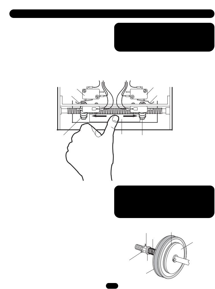
A D J U S T M E N T

 WARNING
To avoid SERIOUS personal INJURY or DEATH from electrocution, disconnect electric power BEFORE manually moving limit nuts.
CLUTCH ADJUSTMENT
Adjust clutch so that it is tight enough to open and close the door but will slip when the door meets an obstruction. Either loosen or tighten the clutch nut with 1/4 turn increments The clutch will require periodic inspection and adjustment.
CAUTION: The adjustable friction clutch is NOT an automatic reversing device. An electric or pneumatic reversing edge can be added to bottom edge of door if desired.
 WARNING
To prevent possible SERIOUS INJURY or DEATH, install reversing sensors when the 3-button control station is out of sight of the door or ANY other control (automatic or manual) is used. Reversing devices are recommended for ALL installations.
Adjusting Nut |
Clutch Pad |
Spring |
|
Clutch Plate
Cotter |
Washer |
Pin |
|
|
Clutch Pulley |
6
 Loading...