


 Loading...
Leica Viva GNSS
Getting Started Guide
Version 3.5
English

Viva GNSS, Introduction |
2 |
Introduction
)To use the product in a permitted manner, please refer to the detailed safety instructions in the Leica CS10/CS15 User Manual and the Leica GS10/GS15 User Manual.
)For detailed descriptions of all functions and settings of the product and applications, please refer to the Leica Viva Series Technical Reference Manual.
Purpose of this |
This Getting Started Guide is intended as a quick field reference manual for immedi- |
||
manual |
ately getting started with your Leica Viva Series equipment. The manual explains what |
||
|
you can find in your container, how everything fits together and how to get started |
||
|
on the basic applications. |
|
|
Quick references |
|
|
|
|
|
||
Topic |
Refer to |
||
to specific topics |
|||
What’s in my container? |
Chapter 1.1 |
||
|
|||
|
|
|
|
|
How does the equipment all fit together? |
Chapter 1.2 |
|
|
|
|
|
|
What is this first screen I see when I turn on my instrument? |
Chapter 2.1 |
|
|
|
|
|
|
How do I get to the Main Menu? |
Chapter 2.1 |
|
|
|
|
|
|
How do I select things and move around the screens? |
Chapter 2.2 |
|
|
|
|
|
|
What are wizards? |
Chapter 2.2 |
|
|
|
|
|
|
How do I get started with jobs and codelists? |
Chapter 3 |
|
|
|
|
|

Topic |
Refer to |
How to use the applications? |
Chapter 4 |
|
|
|
|
myWorld@Leica Geosystems (https://myworld.leica-geosystems.com) offers a wide range of services, information and training material.
With direct access to myWorld, you are able to access all relevant services whenever it is convenient for you, 24 hours a day, 7 days per week. This increases your efficiency and keeps you and your equipment instantly updated with the latest information from Leica Geosystems.
Service |
Description |
myProducts |
Simply add all Leica Geosystems products that you and your |
|
company own. View detailed information on your products, buy |
|
additional options or Customer Care Packages (CCPs), update your |
|
products with the latest software and keep up-to-date with the |
|
latest documentation. |
|
|
myService |
View the service history of your products in Leica Geosystems |
|
Service Centers and detailed information on the services performed |
|
on your products. For your products that are currently in Leica |
|
Geosystems Service Centers view the current service status and the |
|
expected end date of service. |
|
|
Viva GNSS, Introduction |
3 |
Viva GNSS, Introduction |
4 |
|
|
|
|
|
Service |
Description |
|
mySupport |
Create new support requests for your products that will be |
|
|
answered by your local Leica Geosystems Support Team. View the |
|
|
complete history of your Support and view detailed information on |
|
|
each request in case you want to refer to previous support |
|
|
requests. |
|
|
|
|
myTraining |
Enhance your product knowledge with the Leica Geosystems |
|
|
Campus - Information, Knowledge, Training. Study the latest online |
|
|
training material or download training material on your products. |
|
|
Keep up-to-date with the latest News on your products and |
|
|
register for Seminars or Courses in your country. |
|
|
|
|
|
|

Table of Contents
In this manual |
Chapter |
|
|
Page |
|
1 Equipment |
|
8 |
|
|
1.1 |
Container Contents |
8 |
|
|
1.2 |
Setting up as a Post-Processing Base |
15 |
|
|
1.3 |
Setting up as a Real-Time Base |
21 |
|
|
1.4 |
Setting up as a Real-Time Rover |
28 |
|
|
1.5 |
Setting up Viva Uno |
37 |
|
|
1.6 |
Setting up Viva NetRover |
44 |
|
|
1.7 |
Using the Backpack |
47 |
|
|
1.8 |
Fixing the CS to a Holder and Pole |
50 |
|
|
2 SmartWorx Viva and Principles |
54 |
||
|
2.1 |
SmartWorx Viva |
54 |
|
|
|
2.1.1 |
Screen |
56 |
|
|
2.1.2 |
Icons |
60 |
|
|
2.1.3 |
Main Menu |
65 |
|
|
2.1.4 |
Leica Favourites |
68 |
|
|
2.1.5 |
Active Assist |
71 |
|
2.2 |
Operating Principles |
73 |
|
Viva GNSS, Table of Contents |
5 |
Viva GNSS, Table of Contents |
|
|
6 |
||
|
|
2.3 |
Webserver |
|
79 |
|
|
|
2.3.1 |
Home |
79 |
|
|
|
2.3.2 |
Icons |
81 |
|
|
|
2.3.3 |
Go to Work! - Wake-Up |
82 |
|
|
|
2.3.4 |
Current Status |
83 |
|
|
|
2.3.5 |
Instrument |
84 |
|
|
|
2.3.6 |
User |
85 |
3 |
Jobs & Data |
|
86 |
||
|
|
3.1 |
Creating a New Job |
86 |
|
|
|
3.2 |
Creating a Codelist |
88 |
|
|
|
3.3 |
Importing ASCII Data into a Job |
92 |
|
4 |
Applications |
|
96 |
||
|
|
4.1 |
Survey |
|
97 |
|
|
4.2 |
Stakeout |
|
100 |
|
|
4.3 |
Reference Line |
105 |
|
|
Appendix A Working with Memory Devices |
108 |
|||
|
|
A.1 |
Formatting a Memory Device |
108 |
|
|
|
A.2 |
Directory Structure of the Memory Device |
111 |
|

Appendix B Uploading System Files |
114 |
|
Appendix C |
Leica Geo Office |
117 |
Viva GNSS, Table of Contents |
7 |

Viva GNSS, Equipment |
8 |
1Equipment
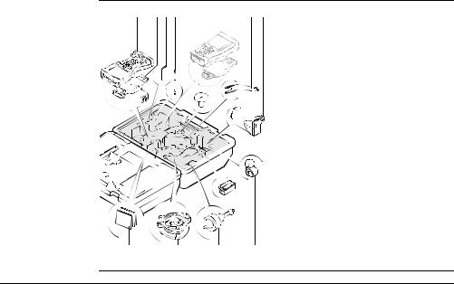
1.1Container Contents
Container for GS10 |
a |
b |
c |
d e |
|
instrument and |
|
|
|
|
|
|
|
|
|
|
|
delivered accesso- |
|
|
|
|
|
ries part 1 of 2 |
|
|
|
|
|
|
|
|
|
|
|
|
a) |
GS10 instrument |
|
|
|
|
|
|
|
b) |
Single/double arm for antennas of |
|
|
|
|
|
|
|
|
devices |
|
|
|
|
|
|
|
c) |
GFU device such as radio |
|
|
|
|
|
|
|
d) |
Antennas of device |
|
|
|
|
|
|
|
e) |
GAD32 telescopic rod |
|
|
|
|
|
|
|
||
|
|
|
|
|
|
|
f) |
GEB221 batteries |
|
|
|
|
|
|
|
g) |
Height hook |
|
|
|
|
|
|
|
h) |
Cables |
|
|
|
|
|
|
|
i) |
Antenna and GAD31 adapter |
f |
g |
h |
i |
j |
j) |
SD cards |
||
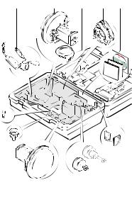
Container for GS10 instrument and delivered accessories part 2 of 2
SYS13_022
a)CS15 field controller
b)GHT62 holder for CS field controller on pole
c)Allen key
d)Supplied stylus
e)GHT36 base for telescopic rod
f)GAD33 arm 15 cm
g)GFU device such as radio
h)Manual & DVD
i)Tribrach
j)GRT146 carrier
k)GEB221 battery
l)GHT63 clamp
Viva GNSS, Equipment |
9 |
Viva GNSS, Equipment |
10 |
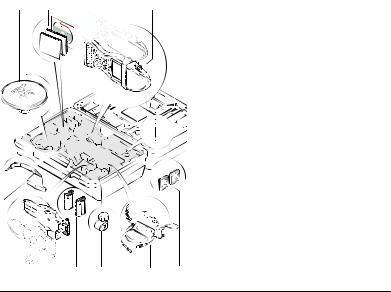
Container for GS15 instrument and delivered accessories part 1 of 2
a |
b |
c |
d |
e |
|
|
|
|
|
|
|
a) |
GDC221 car adapter |
|
|
|
|
|
|
|
|
|||
|
|
|
|
|
|
|
b) |
GS15 instrument |
|
|
|
|
|
|
|
|
c) |
Cables |
|
|
|
|
|
|
|
|
d) |
Tribrach |
|
|
|
|
|
|
|
|
|||
|
|
|
|
|
|
|
e) |
Manuals and DVD |
|
|
|
|
|
|
|
|
f) |
TNC QN-adapter |
|
|
|
|
|
|
|
|
g) |
GAD31 adapter |
|
|
|
|
|
|
|
|
h) |
GRT247 carrier |
|
f g |
b |
h |
i |
||||||
i) |
SD cards |
||||||||
SYS13_17 |
|
|
|
|
|
||||
|
|
|
|
|
|
|
|
|
|
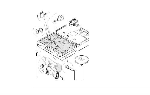
Container for GS15 instrument and delivered accessories part 2 of 2
a b c |
d |
e |
f |
g |
|
|
|
|
|
a) |
GAD108 arm |
|
|
|
|
|
b) |
GAD34 arm 3 cm |
|
|
|
|
|
c) |
GHT36 base for telescopic rod |
|
|
|
|
|
d) |
GEB211/GEB212 batteries |
|
|
|
|
|
e) |
Allen key |
|
|
|
|
|
f) |
CS field controller |
|
|
|
|
|
g) |
GHT62 holder for CS field controller |
|
|
|
|
|
|
on pole |
|
|
|
|
|
h) |
Antennas of device |
|
|
|
|
|
i) |
GAD32 telescopic rod |
|
|
|
|
|
j) |
Height hook |
|
|
|
|
|
||
|
|
|
|
|
k) |
GHT63 clamp |
|
|
|
|
|
||
SYS13_018 |
h i |
j |
k l |
l) |
Supplied stylus |
|
|
|
|
|
|
|
|
Viva GNSS, Equipment |
11 |
Viva GNSS, Equipment |
12 |
Container for Viva Uno instrument and delivered accessories
part 1 of 2
a) Antenna and GAD31 adapter b) Manual & DVD
c) CS field controller with GS GNSS antenna cap
d) Supplied stylus e) Height hook
f) GHT62 holder for CS field controller on pole
g) GEB211 batteries h) GHT63 clamp
i) GDC221 car adapter
j) SD cards/CompactFlash cards
Container for Viva |
a |
b |
c |
d |
|||
Uno instrument |
|
|
|
|
|
|
|
and delivered |
|
|
|
|
|
|
|
accessories |
|
|
|
|
|
|
|
|
|
|
|
|
|
|
|
part 2 of 2 |
|
|
|
|
|
|
|
e
SYS13_32 f g h
a)SD cards/CompactFlash cards
b)GEB211 batteries
c)GRT146 carrier
d)Tribrach
e)Allen key
f)Viva Uno instrument (CS field controller with GS GNSS antenna cap)
g)GHT61 hand strap
h)Antenna and GAD31 adapter
Viva GNSS, Equipment |
13 |

Viva GNSS, Equipment |
14 |
Container for Viva NetRover instrument and delivered accessories
a |
b |
|
c |
d |
e |
|
f |
|
g |
h |
|
i |
j |
SYS_035 |
|
|
|
|
|
|
a)CS10 field controller
b)GHT62 holder for CS10 field controller on pole
c)GDC221 car adapter
d)Cable
e)Manual & DVD
f)Supplied stylus
g)GEB211 batteries
h)GHT63 clamp
i)GS08 GNSS antenna
j)SD card/CompactFlash card

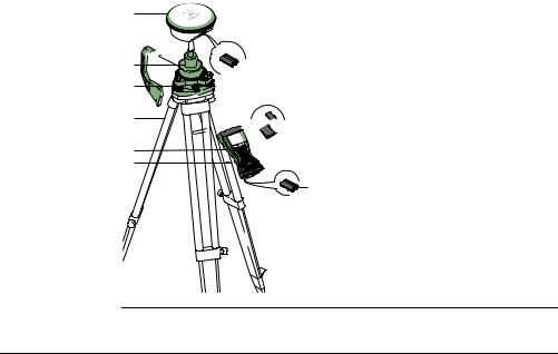
1.2Setting up as a Post-Processing Base
Use |
The equipment setups described following are to be used for static operations over |
|
markers. |
Description |
|
The instrument can be programmed with the CS field controller before use which can |
|
|
then be omitted from the setup. |
)• GNSS antenna/GS12 instrument/GS15 instrument is mounted directly using screw fitting. If using stub and adapter, procedures can vary slightly.
•When using the adapter and carrier, ensure that the GNSS antenna/GS12 instrument/GS15 instrument and the adapter assembly slide down the full length of the carrier stub. An incorrectly mounted GNSS antenna/GS12 instrument/GS15 instrument will have a direct effect on the results.
•GNSS antennas are AS05 or AS10. Procedures/setup can vary if AR10, AR25 or AT504 GG is used.
)If the instrument is left in the container during use in high temperatures, the lid should be left open. Refer to the GS10/GS15 User Manual for operating and storage temperatures.
)Use an external battery such as GEB171 to ensure operation for a full day.
Viva GNSS, Equipment |
15 |

Viva GNSS, Equipment |
16 |
Equipment setup - GS10
a |
|
|
|
b |
|
|
|
c |
|
|
|
d |
|
|
|
e |
|
|
|
f |
h |
|
|
|
i |
|
|
g |
i |
a) |
GNSS antenna AS05/AS10 |
|
b) |
GRT146 carrier |
|
|
j |
||
|
c) |
Height hook |
|
|
|
||
|
k |
d) |
Tribrach |
|
l |
e) |
2.8 m antenna cable |
|
f) |
GS10 instrument |
|
|
|
||
|
|
g) |
Tripod |
|
|
h) |
GEB221 batteries |
|
|
i) |
SD card |
|
|
j) |
CompactFlash card |
|
|
k) |
CS field controller |
GS_107 |
|
l) |
GEB211/GEB212 battery |
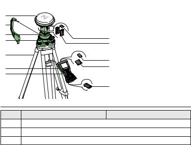
Equipment setup -
GS12 |
a |
|
b


 c
c
d
e
f g
GS_125
 h
h


 i
i 


 j
j
|
a) |
GS12 instrument |
|
b) |
Height hook |
h |
c) |
GRT146 carrier |
|
d) |
Tribrach |
|
e) |
Tripod |
|
f) |
CS field controller |
|
g) |
GHT61 hand strap |
|
h) |
GEB211/GEB212 battery |
|
i) |
SD card |
|
j) |
CompactFlash card |
Viva GNSS, Equipment |
17 |
Viva GNSS, Equipment |
18 |
Equipment setup - GS15
Equipment setup step-by-step
a |
|
|
|
|
b |
|
|
|
|
c |
h |
a) |
GS15 instrument |
|
d |
b) |
Height hook |
||
i |
||||
|
||||
|
|
c) |
GRT247 carrier |
|
e |
h |
d) |
Tribrach |
|
|
e) |
Tripod |
||
f |
j |
f) |
CS field controller |
|
|
g) |
GHT61 hand strap |
||
g |
|
|||
|
|
h) |
SD card |
|
|
k |
i) |
GEB211/GEB212 batteries |
|
|
|
j) |
CompactFlash card |
|
GS_111 |
|
k) |
GEB211/GEB212 battery |
|
Step |
Description |
|
|
1.Set up the tripod.
2.Mount and level the tribrach on the tripod.
3.Ensure that the tribrach is over the marker.

Step Description
4.Place and lock the carrier in the tribrach.
|
GS10 |
GS12/GS15 |
5. |
Screw the GNSS antenna onto the |
Insert the SD card (only GS15) and |
|
carrier. |
the batteries into the GS12/GS15. |
6.Check that the tribrach is still level. Screw the GS12/GS15 onto the
|
|
carrier. |
7. |
Insert the batteries into the instru- |
Check that the tribrach is still level. |
|
ment. |
|
|
|
|
8. |
Insert the SD card into the instru- |
Insert the SD card or CompactFlash |
|
ment. |
card and the battery into the CS field |
|
|
controller. |
|
|
|
9. |
Connect the instrument to the GNSS |
- |
|
antenna using the antenna cable |
|
|
and port ANT on the instrument. |
|
10.Switch on the CS field controller and connect it to the instrument if neces-
sary.
) Mandatory for the GS12 and optional for the GS10/GS15.
Viva GNSS, Equipment |
19 |

Viva GNSS, Equipment |
|
20 |
|
|
|
|
|
|
Step |
Description |
|
|
11. |
To hang the instrument on the |
To hang the CS field controller on |
|
|
tripod leg, use the hook on the rear |
the tripod leg, use the hook on the |
|
|
of the unit. Or place the instrument |
hand strap. Refer to the CS10/CS15 |
|
|
in the container. |
User Manual. |
|
|
|
|
12.Insert the height hook into the carrier.
13.Measure the antenna height using the height hook.
14.Press the ON/OFF button on the instrument for at least 2 s to switch on the instrument .
1.3Setting up as a Real-Time Base
Use |
The equipment setups described following are to be used for real-time base stations |
|
with the need of optimal radio coverage. Raw observation data can also be collected |
|
for post-processing. |
Description |
|
The GS10 instrument clips to the tripod leg. Connections are made to the GNSS and |
|
|
radio antenna. The radio antenna is mounted on the antenna arm which clips to the |
|
GNSS antenna. The GS10/GS15 instrument can be programmed with the CS field |
|
controller before use which can then be omitted from the setup. |
|
The GS10 instrument can be used as a DGPS base station, if fitted with the DGPS |
|
option, and as a real-time base station. |
|
The connection between GS15 and CS field controller is made via Bluetooth. |
)• GNSS antenna/GS15 instrument is mounted directly using screw fitting. If using stub and adapter, procedures can vary slightly.
•When using the adapter and carrier, ensure that the GNSS antenna and the adapter assembly slide down the full length of the carrier stub. An incorrectly mounted GNSS antenna will have a direct effect on the results.
Viva GNSS, Equipment |
21 |

Viva GNSS, Equipment |
22 |
•Standard radio is used throughout the instructions. Digital cellular phones can also be used but the setup can differ slightly.
•GNSS antennas are AS05 or AS10. Procedures/setup can vary if AR10, AR25 or AT504 GG is used.
)If the instrument is left in the container during use in high temperatures, the lid should be left open. Refer to the GS10/GS15 User Manual for operating and storage temperatures.
)Use an external battery such as GEB171 to ensure operation for a full day.

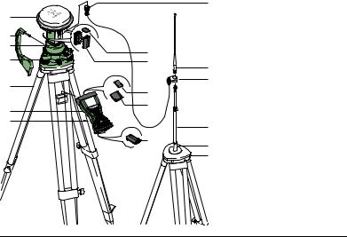
Equipment setup - GS10
|
|
a) |
Radio antenna |
|
a |
|
b) |
GAD33 arm 15 cm |
|
|
c) |
GNSS antenna AS05/AS10 |
||
b |
|
d) |
Height hook |
|
|
e) |
GRT146 carrier |
||
|
|
|||
c |
k |
f) |
Tribrach |
|
d |
g) |
1.2 m antenna cable |
||
|
|
(instrument/GNSS |
||
e |
|
|
||
l |
|
antenna) |
||
f |
|
|||
m |
h) |
Tripod |
||
g |
i) |
GS10 instrument |
||
|
||||
h |
|
j) |
Radio in housing |
|
|
m |
k) |
1.2 m antenna cable |
|
i |
|
(radio housing/radio |
||
n |
|
|||
|
|
antenna) |
||
|
|
|
||
j |
o |
l) |
GEB221 batteries |
|
|
|
m) |
SD card |
|
|
p |
n) |
CompactFlash card |
|
GS_108 |
|
o) |
CS field controller |
|
|
|
|||
|
|
p) |
GEB211/GEB212 battery |
Viva GNSS, Equipment |
23 |
Viva GNSS, Equipment |
24 |
Equipment setup -
GS15
a |
|
|
b |
|
|
c |
h |
|
d |
||
i |
||
|
||
e |
h |
|
|
||
f |
j |
|
|
||
g |
|
|
|
k |
GS_117
la) GS15 instrument with
|
|
RTK slot-in device |
|
b) |
Height hook |
|
c) |
GRT247 carrier |
|
d) |
Tribrach |
m |
e) |
Tripod |
n |
f) |
CS field controller |
|
g) |
GHT61 hand strap |
|
h) |
SD card |
|
i) |
GEB211/GEB212 |
|
|
batteries |
oj) CF card
p |
k) |
GEB211/GEB212 battery |
e |
l) |
GAD109 transition |
|
|
adapter |
|
m) |
RTK antenna |
|
n) |
GAD34 arm 3 cm |
|
o) |
GAD32 telescopic rod |
|
p) |
GHT36 base for tele- |
|
|
scopic rod |

Equipment setup step-by-step
Step Description
1.Set up the tripod.
2.Mount and level the tribrach on the tripod.
3.Ensure that the tribrach is over the marker.
4.Place and lock the carrier in the tribrach.
|
GS10 |
GS15 |
5. |
Screw the GNSS antenna onto the |
Insert the SD card and the batteries |
|
carrier. |
into the GS15. |
6.Check that the tribrach is still level. Press the ON/OFF button on the
|
|
GS15 for at least 2 s to switch on |
|
|
the GS15. |
|
|
|
7. |
Insert the SD card and the batteries |
Screw the GS15 onto the carrier. |
|
into the instrument. |
|
|
|
|
8. |
Connect the instrument to the GNSS |
Check that the tribrach is still level. |
|
antenna using the antenna cable |
|
|
and port ANT on the instrument. |
|
|
|
|
9. |
Connect the CS field controller to the |
Insert the SD card or CompactFlash |
|
instrument if necessary. |
card and the battery into the CS field |
|
|
controller. |
Viva GNSS, Equipment |
25 |

Viva GNSS, Equipment |
|
26 |
|
|
|
|
|
|
Step |
Description |
|
|
10. |
To hang the instrument on the |
Connect the CS field controller to the |
|
|
tripod leg, use the hook on the rear |
instrument if necessary. |
|
|
of the unit. Or place the instrument |
|
|
|
in the container. |
|
|
|
|
|
|
11. |
Insert the height hook into the |
To hang the CS field controller on |
|
|
carrier. |
the tripod leg, use the hook on the |
|
|
|
hand strap. Refer to the CS10/CS15 |
|
|
|
User Manual. |
|
|
|
|
|
12. |
Measure the antenna height using |
Insert the height hook into the |
|
|
the height hook. |
carrier. |
|
|
|
|
|
13. |
Clip the antenna arm to the GNSS |
Measure the antenna height using |
|
|
antenna. |
the height hook. |
|
|
|
|
|
14. |
Screw the radio antenna onto the |
Press the ON/OFF button on the |
|
|
antenna arm. |
instrument for at least 2 s to switch |
|
|
|
on the instrument. |
|
|
|
|
|
15. |
Attach the radio in its housing to |
- |
|
|
port P2 or P3 on the instrument. |
|
|
|
|
|
|
16. |
Connect the radio antenna to the |
- |
|
|
radio using the second 1.2 m |
|
|
|
antenna cable. |
|
|
|
|
|

Step |
Description |
|
17. |
Press the ON/OFF button on the |
- |
|
instrument for at least 2 s to switch |
|
|
on the instrument. |
|
|
|
|
|
|
|
Viva GNSS, Equipment |
27 |

Viva GNSS, Equipment |
28 |
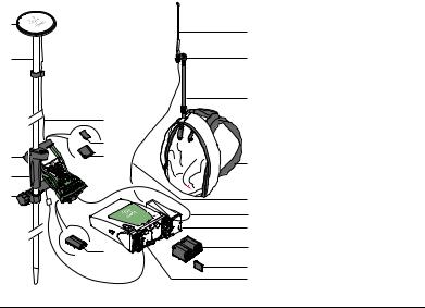
1.4Setting up as a Real-Time Rover
Use |
The equipment setups described following are to be used for real-time rover with |
|
extended periods of use in the field. |
Description |
|
The radio attaches to the GS10 instrument and is placed in the backpack. Connec- |
|
|
tions are made to the GNSS antenna, radio antenna and CS field controller. The |
|
cables coming from the backpack can be disconnected when an obstacle such as a |
|
fence has to be crossed. |
|
The CS field controller is fixed to the pole with the GHT62. Connection between the |
|
GS12/GS15 instrument and the CS field controller is made via Bluetooth. |
)• GNSS antenna/GS12 instrument/GS15 instrument is mounted directly using screw fitting. If using stub and adapter, procedures can vary slightly.
•When using the pole with stub, ensure that the GNSS antenna/GS12 instrument/GS15 instrument and the screw-to-stub adapter slide down the full length of the stub before tightening the locking ring. An incorrectly mounted GNSS antenna/GS12 instrument/GS15 instrument will have a direct effect on the results.
•Aluminium poles are used. They can be replaced with their carbon fibre equivalent without any change to these instructions.

•Standard radio is used throughout the instructions. Digital cellular phones can also be used but the setup can differ slightly.
•GNSS antennas are AS05 or AS10. Procedures/setup can vary if AR10, AR25 or AT504 GG is used.
Viva GNSS, Equipment |
29 |
Viva GNSS, Equipment |
30 |
Equipment setup - GS10
a |
|
j |
a) |
GNSS antenna AS05/AS10 |
|
|
|
b) |
Pole |
||
|
|
|
|||
b |
|
k |
c) |
CS field controller |
|
|
d) |
Grip for pole |
|||
|
|
|
|||
|
|
|
e) |
GHT62 holder |
|
|
|
l |
f) |
Antenna cable |
|
|
f |
|
g) |
SD card |
|
|
|
h) |
CompactFlash card |
||
|
g |
|
i) |
GEB211/GEB212 battery |
|
|
|
j) |
Radio antenna |
||
c |
h |
m |
|||
k) |
GAD34 arm 3 cm |
||||
|
|
||||
d |
|
|
l) |
Telescopic rod |
|
e |
|
n |
m) |
Backpack |
|
|
n) |
1.2 m antenna cable |
|||
|
|
||||
|
|
o |
|||
|
|
|
(radio housing - radio |
||
|
|
p |
|
antenna) |
|
|
|
|
|
||
|
i |
q |
o) |
1.8 m, CS to GS10 cable |
|
|
|
g |
p) |
Radio in housing |
|
|
|
q) |
GEB221 batteries |
||
|
|
r |
|||
|
|
r) |
GS10 instrument |
||
GS_101 |
|
|
Loading...