


IFC-020
Installation and
operating instructions
IFC 020 K
IFC 020 F
IFC 020 E
Signal converters for
electromagnetic flowmeters
DIN A4: 7.10003.32.00
©
KROHNE 12/2002 US size: 7.10003.72.00
GR
Applicable to
Software Versions
● IFC 020 K and
IFC 020 F
No. 3170330200
● IFC 020 E
No. 3175870200
How to use these Instructions
The flowmeters are supplied ready for operation.
The primary head must be installed in the pipeline as described in the installation
instructions inside the packing of the primary head.
– Installation location and connection to power (Section 1) Pages 1/1-1/8
– Electrical connection of outputs and inputs (Section 2) Pages 2/1-2/4
– Factory settings and start-up (Section 3) Pages 3/1-3/2
Power the flowmeter. THAT’S ALL. The system is operative.
Pull-out
Condensed Instructions
Variable area flowmeters
Vortex flowmeters
Flow controllers
Electromagnetic flowmeters
Ultrasonic flowmeters
Mass flowmeters
Level measuring instruments
Communications technology
Engineering systems & solutions
Switches, counters, displays and recorders
Heat metering
Pressure and temperature

Installation and operating instructions IFC 020
0/1
Contents
Versions IFC 020 signal converter 0/3
Items included with supply 0/3
Software history 0/3
System description 0/4
Product liability and warranty 0/4
CE / EMC / Standards / Approvals 0/4
Part A System installation and start-up 1/1-3/2
1 Electrical connection: power supply 1/1-1/8
1.1 Important installation notes – PLEASE NOTE ! 1/1
1.1.1 Location 1/1
1.1.2 Only for separate systems/signal converters (F- and E versions) 1/1
1.1.3 Cable entries (K- and F versions) 1/1
1.2 Connection to power 1/2
1.3 Electrical connection of separate primary head (F- and E versions) 1/3-1/6
1.3.1 General information on signal cable A and B as well as field current cable C 1/3
1.3.2 Grounding of primary head 1/3
1.3.3 Stripping (preparation) of signal cable A and B 1/4
1.3.4 Cable length (max. distance between signal converter and primary head) 1/5
1.3.5 Connection diagrams I and II (IFC 020 F signal converter and primary head) 1/6
1.3.6 Connection diagrams III and IV (IFC 020 E signal converter and primary head) 1/7-1/8
2
Electrical connection of outputs and inputs 2/1-2/4
2.1 Current output I 2/1
2.2 Pulse output P and status output S 2/1
2.3 Control input E (applicable with IFC 020 E only) 2/2
2.4 Connection diagrams for outputs and inputs 2/3-2/4
3.
Start-up 3/1-3/2
3.1 Power-on and measurement 3/1
3.2 Factory settings 3/1
3.3 Setting data 3/2
Part B IFC 020
/ D Signal converter 4/1-5/12
4 Operation of the signal converter 4/1-4/12
4.1 Krohne operator control concept 4/1
4.2 Operating and check elements 4/2
4.3 Function of keys 4/3-4/4
4.4 Table of settable functions 4/5-4/9
4.5 Error messages in measuring mode 4/10
4.6 Reset totalizer and cancel error messages, RESET/QUIT menu 4/11
4.7 Examples of setting the signal converter 4/12
5
Description of functions 5/1-5/12
5.1 Full-scale range Q100% 5/1
5.2 Time constant 5/1
5.3 Low-flow cutoff SMU 5/2
5.4 Display 5/2-5/3
5.5 Internal electronic totalizer 5/3
5.6 Current output I 5/4
5.7 Pulse output P 5/5-5/6
5.8 Status output S 5/7
5.9 Language 5/8
5.10 Entry code 5/8
5.11 Primary head 5/9
5.12 User-defined unit 5/10
5.13 F/R mode, forward/reverse flow measurement 5/11
5.14 Characteristic of outputs 5/11

Installation and operating instructions IFC 020
0/2
Part C Special applications, functional checks, service, and order numbers 6/1-9/1
6 Special applications 6/1-6/6
6.1 HART interface 6/1-6/2
6.2 KROHNE
RS 485 interface
6/2
6.3 Stable signal outputs when measuring tube empty 6/3-6/4
6.4 Pulsating flow 6/5
6.5 Rapid changes in flowrate 6/5
6.6 Unsteady display and outputs 6/6
7
Functional checks 7/1-7/8
7.1 Zero check, Fct. 3.03 7/1
7.2 Test of measuring range Q, Fct. 2.01 7/1
7.3 Hardware information and error status, Fct. 2.02 7/2
7.4 Faults and symptoms during start-up and process flow measurement 7/2-7/4
7.5 Test of signal converter using GS 8A simulator (option) 7/5-7/8
8
Service 8/1-8/9
8.1 Illustrations used for service work 8/1-8/2
8.2 Replacement of power fuses 8/3
8.3 Changeover of operating voltage on AC Versions 1 and 2 8/4
8.4 Replacement of electronics unit of signal converter 8/5
8.5 Cleaning the signal converter housing 8/5
8.6 Turning the converter housing of the compact flowmeters 8/6
8.7 IFC 020 K and F: Directions for folding the ribbon cable on the display unit 8/7
8.8 IFC 020 K and F: Illustrations of the PCBs 8/8
8.9 IFC 020 E: Illustrations of the PCBs 8/9
9
Order numbers 9/1
Part D Technical data, measuring principle and block diagram 10/1-12/1
10 Technical data 10/1-10/7
10.1 Full-scale range Q
100%
10/1
10.2 Error limits at reference conditions 10/2
10.3 IFC 020 signal converter 10/3-10/4
10.4 Dimensions and weights 10/5-10/6
10.5 Instrument name plates 10/7
1
1 Measuring principle 11/1
12 Block diagram - signal converter 12/1
Part E Index E1-E2
Printed form to accompany flowmeters returned to Krohne E3
5.15 Applications 5/12
5.16 Setting data 5/12
5.17 Communication interface 5/12
5.18 Control input E (IFC 020 E only) 5/12
Installation and operating instructions IFC 020
0/3
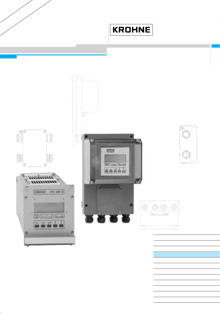
IFC 020 signal converter versions
• All signal converter versions include local display and control elements.
The operating data are factory-set to your ordered specifications
IFC 020 K Compact flowmeter,
Signal converter is directly mounted on primary head.
IFC 020 F Signal converter in field housing,
Electrical connection to primary head via field power and signal cables.
IFC 020 E Signal converter as 19” plug-in unit (in compliance with DIN 41 494, part 5)
Electrical connection to primary head via field power and signal cables.
Items included with supply
• Signal converter in the version as ordered, see above.
• These installation and operating instructions for the signal converter,
including 20-page pull-out condensed instructions for installation, electrical connection,
start-up and operator control of the signal converter.
• 2 plug connectors for connection of power supply and outputs/inputs (K- and F- versions only)
• for separate system version only
, F- and E versions:
signal cable in the version and length as ordered (standard: signal cable A, length 10 m / 30 ft)
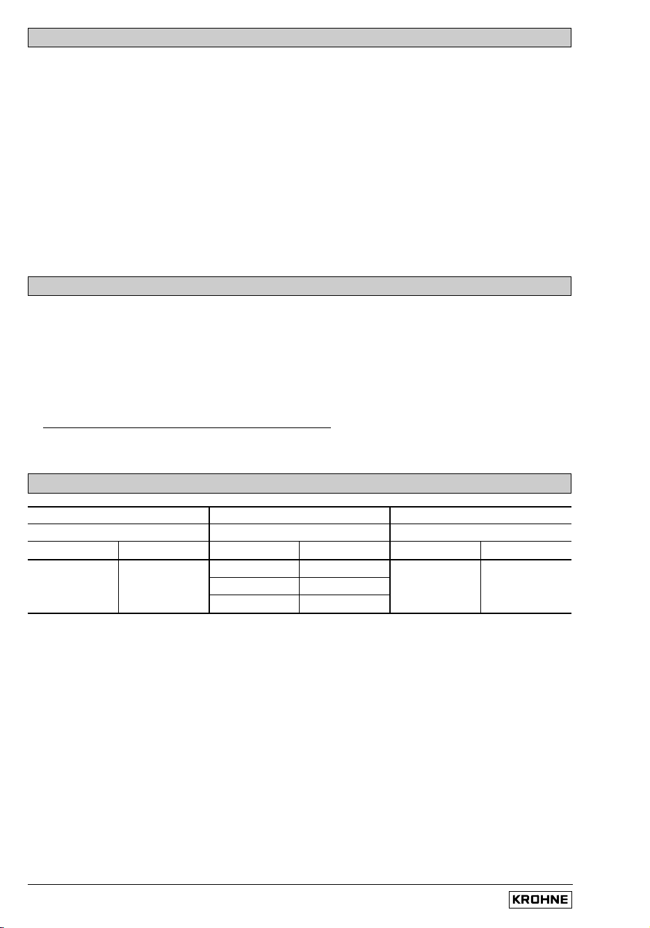
Software history
Display & control unit Handheld HHT 020 CONFIG user software
IFC 020 K and F IFC 020 E ImoCom, RS 485, HART
Software Status Software Status Software Status
3170330100 replaces
3170330200 replaces
3170330200 current 3175870200 current from V 3.15 current
Installation and operating instructions IFC 020
0/4
CE / EMC / Standards / Approvals
System description
Electromagnetic flowmeters with the IFC 020 signal converter are precision instruments designed
for linear flow measurement of liquid products.
The process liquids must be electrically conductive: ≥ 5 µS/cm
(for cold demineralized water ≥ 20 µS/cm).
The full-scale range Q
100%
can be set as a function of the meter size:
Q
100%
= 0.0060 - 86 860 m
3
/hr = 0.03 - 156.672 US Gal/min
This is equivalent to a flow velocity of 0.3 - 12 m/s or 1 - 40 ft/s.
Product liability and warranty
The electromagnetic flowmeters with the IFC 020 signal converter are designed solely for
measuring the volumetric flowrate of electrically conductive, liquid process products.
These flowmeters are not certified for use in hazardous areas. Other flowmeter series are
available for such applications.
Responsibility as to suitability and intended use of these electromagnetic flowmeters rests solely
with the operator.
Improper installation and operation of the flowmeters (systems) may lead to loss of warranty.
In addition, the “General conditions of sale” forming the basis of the purchase contract are
applicable.
If flowmeters need to be returned to Krohne, please note the information given on the last-but-one
page of these Instructions. Krohne regrets that it cannot repair or check your flowmeter(s) unless
accompanied by the completed form sheet.
• Electromagnetic flowmeters with the IFC 020 signal converter meet the protection requirements
of Directive 89/336/EEC in conjunction with EN 50081-1 (1992) and EN 50082-2 (1995),
as well as Directives 73/23/EEC and 93/68/EEC in conjunction with EN 61010-1, and bear the
CE marking.
Installation and operating instructions IFC 020
1/1
Part A System installation and start-up
1 Electrical connection: power supply
1.1 Important installation notes PLEASE NOTE !
1.1.1 Location
• Electrical connection in accordance with VDE 0100 ”Regulations governing heavy-current
installations with line voltages up to 1000 V” or equivalent national regulations.
• Do not cross or loop cables inside the terminal compartment.
• Use separate cable entries (see below) for power supply, field current cables, signal lines,
outputs and inputs.
• Protect flowmeters or switchgear cabinets with built-in devices from direct sunlight.
Fit a sunshade if necessary.
• When installed in switchgear cabinets, signal converters must be adequately cooled,
e.g. use fans or heat exchangers.
• Do not expose signal converters to intense vibration.
1.1.2 Onl
y for separate systems/signal converters (F- and E versions)
• Keep distance between primary head and signal converter as short as possible.
Refer to Sect. 1.3.4 for maximum permissible length of signal and field current cables.
• Use the supplied Krohne signal cable A (Type DS), standard length 10 m (33 ft).
• Always calibrate primary head and signal converter together. Therefore, when installing,
ensure primary constant GK is identical; refer to instrument nameplate for the primary
head. If the GK is not identical, set the signal converter to the GK of the primary head.
Refer also to Section 4.
• Dimensions of signal converter; refer to Section 10.4.
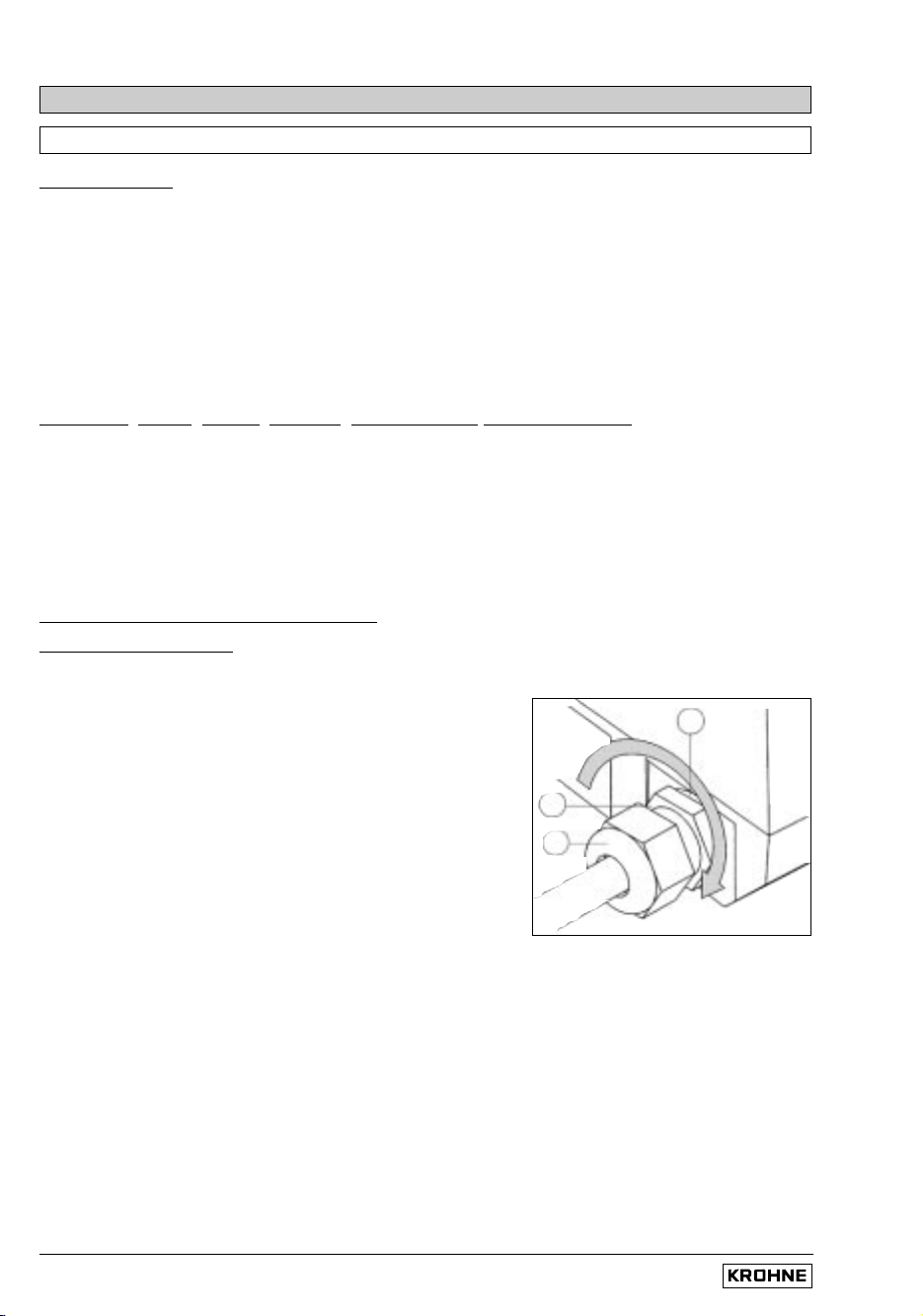
1.1.3 Cable entries (K- and F- versions)
Number of cable entries: 2 for the compact flowmeters
4 for the seperate IFC 020 F signal converter
NOTE: Ensure gaskets are fitted correctly and maintain
the following max. torques!
1 Max. torques for PG 13.5,
1/2“ NPT or 1/2“ PF adapters: 4 Nm / 2.8 ft
x
lbf
2 Max. torques for PG 13.5 only: 3 Nm / 2.1 ft
x
lbf
3 Gasket
A) PG 13.5 cable entries
These cable entries may only be used for flexible electrical cables if the relevant electrical
regulations so allow, e.g. National Electric Code (NEC).
Do not fix rigid metal conduits (IMC) or flexible plastic conduits to the PG 13.5 cable entries, refer
to “Point B/C” below (1/2” NPT or PF adapters).
B) 1/2“ NPT adapters C) 1/2“ PF adapters
For most North American systems the regulations require that electrical conductors be laid in
conduits, particularly where power voltages > 100 V AC are concerned.
In such cases, use the 1/2” NPT or 1/2” PF adapters to which flexible plastic conduits can be
screwed. Do not use rigid metal conduits (IMC)!
Lay conduits such that no moisture can penetrate into the converter housing.
Should there be risk of any condensation water forming, fill the cross-section of the conduit
around the cables at these adapters with a suitable sealing compound.
3
1
2
Installation and operating instructions IFC 020
1/2
Connection to power 1.2
PLEASE NOTE !
• Rated values:
The flowmeter housings protecting the electronic equipment from dust
and moisture must always be kept closed. The selected creepage distances and
clearances have been dimensioned in conformity with VDE 0110 and IEC 664 for
contamination category 2. Supply circuits and output circuits are designed to meet the
standards of overvoltage class II.
• Safet
y isolation: the flowmeters (signal converters) must be provided with an
isolating facility.
1. AC V
ersion 2. AC Version
230/240 V AC (200 - 260 V AC) 200 V AC (170 - 220 V AC)
switch-selectable to switch-selectable to
115/120 V AC (100 - 130 V AC) 100 V AC (85 - 110 V AC)
• Note information on instrument nameplate: supply voltage and frequency
• The PE protective ground conductor for the power supply must be connected to the
separate U-clamp terminal in the terminal compartment of the signal converter.
For exceptions (compact systems), refer to installation instructions for the primary head.
• Connection diagrams for electrical connection between primary head and
signal converter: refer to Section 1.3.5 and 1.3.6.
DC V
ersion (in preparation for IFC 020 E)
24 V DC (18 - 32 V DC)
• Note information on instrument nameplate: supply voltage and frequency.
• For measurement reasons, connect an FE functional ground conductor to the separate
U-clamp terminal in the terminal compartment of the signal converter.
• If connected to a functional extra-low voltage source (24 V AC / DC, 48 V AC),
provide for protective separation (PELV) in conformity with VDE 0100 / VDE 0106 or
IEC 364 / IEC 536, or equivalent national regulations.
• Connection diagrams for power supply and electrical connection between primary
head and signal converter: refer to Section 1.3.6.
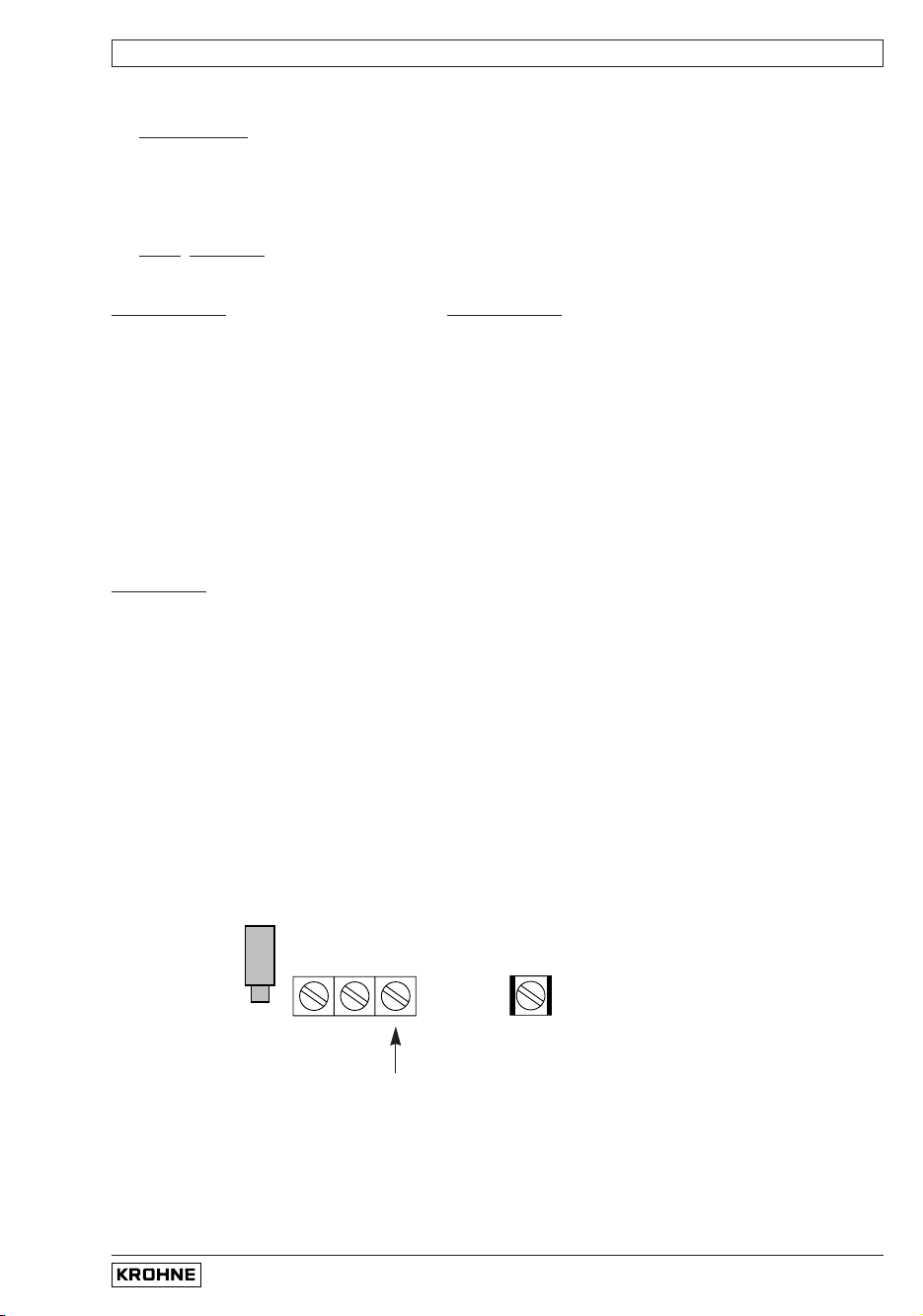
Connection to power (K- and F- versions only)
Power fuse F1
(see Sect. 8.2)
AC: 100 – 240 V
DC: 24 V
Power supply
U-clamp terminal
PE protective conductor
FE functional ground conductor
L N
1L = 0L =
for
internal
use only
For electrical connection of the IFC 020 E power supply see Section 1.3.6,
connection diagrams III to VI.
Installation and operating instructions IFC 020
Field current line C (single shielding with IFC 020 F)
Line 2 x 0.75 mm
2
(18 AWG) Cu, 2 x 1.5 mm
2
(14 AWG) Cu or 2 x 2.5mm
2
(12 AWG) Cu
single shielding (Cu = copper cross section)
The cross section depends on the required cable length, see table in Section 1.3.4.
1/3
1.3
Electrical connection of separate primary heads (F- and E- versions)
1.3.1
General remarks on signal lines A and B and field current line C
Proper operation of the equipment is ensured when Krohne signal lines A and B are used with foil
screen and magnetic shield.
• Signal lines must be firmly installed.
• Shields are connected via stranded drain wires.
• Underwater or underground routing is possible.
• Insulating material flame-retardant to IEC 332.1 / VDE 0742.
• Low-halogen, unplasticized signal lines which remain flexible at low temperatures.
Si
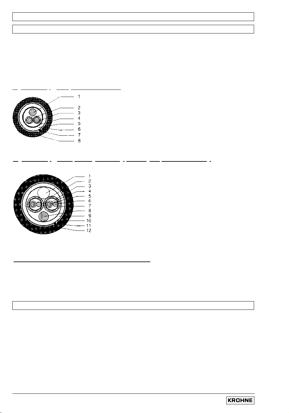
gnal line A (type DS) with double shielding
1.3.2 Grounding of primary head
• All flowmeters must be properly grounded.
• The grounding conductor should not transmit any interference voltages.
• Do not ground any other electrical device together with this conductor.
• The primary head is connected to ground by means of an FE functional ground conductor.
• Special information on grounding various primary heads is contained in the separate
installation instructions for primary heads.
• These instructions also contain detailed descriptions on how to use grounding rings and
how to install primary heads in metal or plastic pipes or internally coated pipelines.
1 Stranded drain wire, 1st shield, 1.5 mm
2
or AWG 14
2 Insulation
3 Stranded wire 0.5 mm
2
or AWG 20 (3.1 red/3.2 white)
4 Special foil, 1st shield
5 Insulation
6 Mu-metal foil, 2nd shield
7 Stranded drain wire, 2nd shield, 0.5 mm
2
or AWG 20
8 Outer sheath
Signal line B (type BTS) with triple shielding (bootstrap line), for IFC 020 E only
1 Dummy glider wire
2 Insulation (2.1 red/2.2 white)
3 Special foil, 1st shield (3.1/3.2)
4 Insulation (4.1/4.2)
5 Stranded wire 0.5 mm
2
or AWG 20 (5.1 red/5.2 white)
6 Stranded drain wire, 1st shield, 0.5 mm
2
or AWG 20
(6.1/6.2)
7 Special foil, 2nd shield
8 Stranded drain wire, 2nd shield, 1.5 mm
2
or AWG 14
9 Insulation
10 Mu-metal foil, 3rd shield
11 Stranded drain wire, 3rd shield, 0.5 mm
2
or AWG 20
12 Outer sheath
Installation and operating instructions IFC 020
1/4
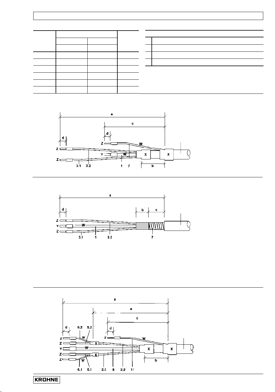
Stripping (preparation) of signal cable A and B 1.3.3
Please note the different lengths given in the table for signal converter and primary head.
Customer-supplied materials
W
Insulation tubing (PVC), Ø 2.0 - 2.5 mm (dia. 1”)
X Heat-shrinkable tubing or cable sleeve
Y Wire end sleeve to DIN 41 228: E 1.5-8
Z Wire end sleeve to DIN 41 228: E 0.5-8
For cable fixation in signal converter housing IFC 020 F
see illustration in Section 10.4
External shielding of signal cable A (Type DS)
Wrap stranded drain wire (7) around the mu-metal foil (6) and clamp under the shield terminal in
the signal converter terminal box (see also diagram in Sect. 1.3.5).
Signal cable A (type DS) double shielding, for primary head and IFC 020 E
Signal cable A (type DS) double shielding, for IFC 020 F
Signal cable A
bending radius
≥ 50 mm (≥2“)
Signal cable A
bending radius
≥ 50 mm (≥2“)
Signal line B (type BTS) with triple shielding (bootstrap), for IFC 020 E
Signal line B
bending radius
≥ 50 mm (≥2”)
Length
Converter Primary
mm IFC 020 F + E only IFC 020 E
head
(inch) Signalcable A Signalcable B
a 55 (2.17) 70 (2.76) 90 (3.54)
b 10 (0.39) 50 (1.97) 98 (0.31)
c 15 (0.59) 25 (0.98) 25 (0.98)
d 58 (0.31) 78 (0.31) 98 (0.31)
e – 50 (1.97) 70 (2.76)
f – 78 (0.31) 98 (0.31)
Installation and operating instructions IFC 020
Length
Cross section A
F
(Cu), minimum
0 - 150 m 5 - 500 ft 2 × 0.75 mm
2
Cu / 2 × 18 AWG
150 - 300 m 500 - 1000 ft 2 × 1.50 mm
2
Cu / 2 × 14 AWG
300 - 600 m 1000 - 1900 ft 2 × 2.50 mm
2
Cu / 2 × 12 AWG
Abbreviations and ex
planatory notes
used in the following tables, diagrams and connection diagrams
A Signal cable A (type DS), with double shielding, see diagram A for max. length
B Signal line B (type BTS) with triple shielding, max. length see diagram B (IFC 020 E only)
C Field current cable min. cross-section (A
F
) and max. length,
(with single shielding for IFC 020 F), see Table
D High-temperature silicone cable, 3 × 1.5 mm
2
(14 AWG) Cu, (with single shielding,
max. length 5 m (16 ft)
E High-temperature silicone cable, 2 × 1.5 mm
2
(14 AWG) Cu, max. length 5 m (16 ft)
A
F
Cross section of field current line C in Cu, see table
L Cable length
κκ
Electrical conductivity of the process liquid
ZD Intermediate connection box required in connection with cables D and E for primary heads
ALTOFLUX IFS 4000 F, PROFIFLUX IFS 5000 F and VARIFLUX IFS 6000 F in cases where
process temperatures exceed 150 °C (302 °F)
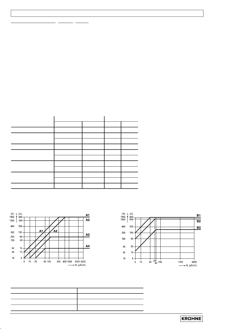
Recommended length of signal cable A (Type DS) and B (Type BTS)
(Signal cable B, Type BTS, for IFC 020 E only)
1.3.4 Cable lengths (max. distance between signal converter and primary head)
Field current cable C: (for IFC 020 F single shielding!)
Primary head Meter size Signal cable
DN mm inch AB
AQUAFLUX F 010 - 1000
3
/8 -40 A1 B1
ECOFLUX IFS 1000 F 010 - 15
3
/8 -
1
/2 A4 B3
025 - 150 1 - 6 A3 B2
ALTOFLUX IFS 2000 F 150 - 250 6 - 10 A1 B1
ALTOFLUX IFS 4000 F 010 - 150
3
/8 - 6 A2 B2
200 - 1000 8 - 40 A1 B1
PROFIFLUX IFS 5000 F 002.5 - 15
1
/10 -
1
/2 A4 B3
025 - 100 1 - 4 A2 B2
VARIFLUX IFS 6000 F 002.5 - 15
1
/10 -
1
/2 A4 B3
025 - 80 1 - 3 A2 B2
ALTOFLUX M 900 010 - 300
3
/8 -12 A1 B1
1/5
Diagram A Diagram B (for IFC 020 E only)
Installation and operating instructions IFC 020
1/6
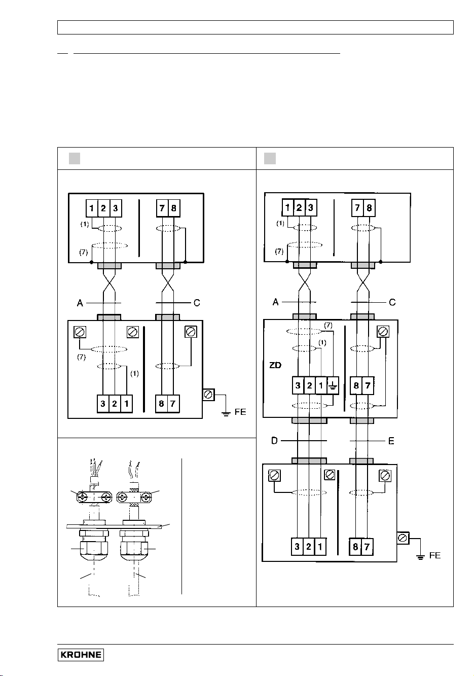
Im
portant information on connection diagrams PLEASE NOTE!
• The figures in brackets indicate the stranded drain wires for the shields,
see cross-sectional drawing of signal cable in Section 1.3.1.
• Electrical connection to VDE 0100 ”Regulations governing heavy-current installations with
line voltages up to 1000 V“ or equivalent national regulations.
•PE= protective conductor FE = functional ground conductor
Connection diagrams I and II (IFC 020 F signal converter and primary head) 1.3.5
I II
Process temperature < 150°C (302 °F) Process temperature > 150°C (302 °F)
Primary heads
Primary heads
1 Signal cable A
(Type DS)
2 Shield terminal
for shielded
signal cable
3 Field power cable
4 Shield terminal
for shielded
field power cable
5 Housing wall,
signal converter
6 Cable entries
Connection of shields at the IFC 020 F
4
5
6
3
1
6
2
IFC 020 F IFC 020 F
Installation and operating instructions IFC 020
1/7
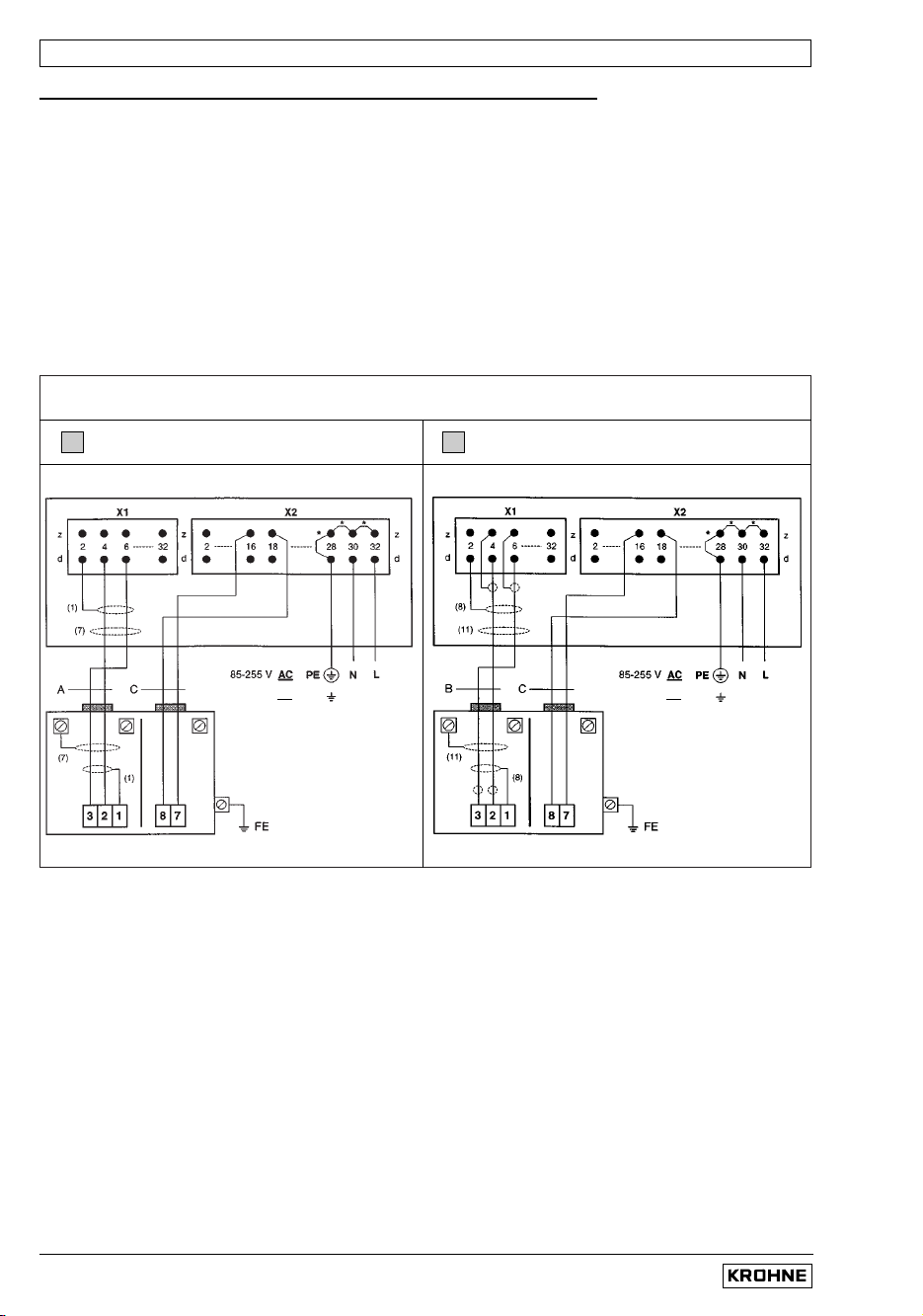
III IV
Signal cable A (type DS) Signal cable B (type BTS)
IFC 020 E
IFC 020 E
Process temperature < 150°C (302°F)
Primary head Primary head
Important information on connection diagrams PLEASE NOTE!
• The figures in brackets indicate the stranded drain wires for the shields
(see cross-sectional drawing of signal cable in Section 1.3.1).
• Electrical connection to VDE 0100 "Regulations governing heavy-current installations
with line voltages up to 1000 V" or equivalent national regulations.
• 24 V DC power supply (in preparation): Functional extra-low voltage with protective
separation in conformity with VDE 0100, Part 410 or equivalent national regulations.
•
For IFC 020 E, please note: The internal bridges marked with *
are needed for power supply > 100 V AC only.
•PE= Protective conductor FE = Functional ground conductor
1.3.6 Connection diagrams III to VI (IFC 020 E signal converter and primary head)
24 V DC FE
0L = 1L =
24 V DC FE
0L = 1L =
Installation and operating instructions IFC 020
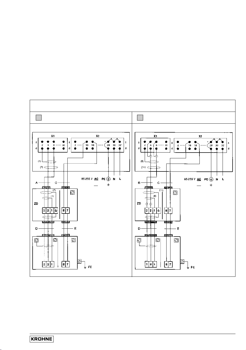
1/8
V
VI
Signal cable A (type DS) Signal cable B (type BTS)
IFC 020 E IFC 020 E
Process temperature > 150°C (302°F)
Primary head Primary head
24 V DC FE
0L = 1L =
24 V DC FE
0L = 1L =
Installation and operating instructions IFC 020
2/1
• All operating data and functions can be set:
Operation
see Section 4 and 5.
7 Function 1.06 and 1.07
.
• The pulse and status outputs can be operated in the active or passive mode.
Active mode: The current output is the internal voltage source,
connection of electronic totalizers (EC)
Passive mode: External DC or AC voltage source required, connection of electronic (EC)
or electromechanical (EMC) totalizers
• Digital pulse division, interpulse period is non-uniform. Therefore, if frequency meters or
cycle counters are connected, allow for minimum counting interval:
gate time, counter ≤
1000
P
100% [ Hz]
• Connection diagrams see Sect. 2.4: diagrams - pulse output
 Ã
diagrams - status output Ä Å
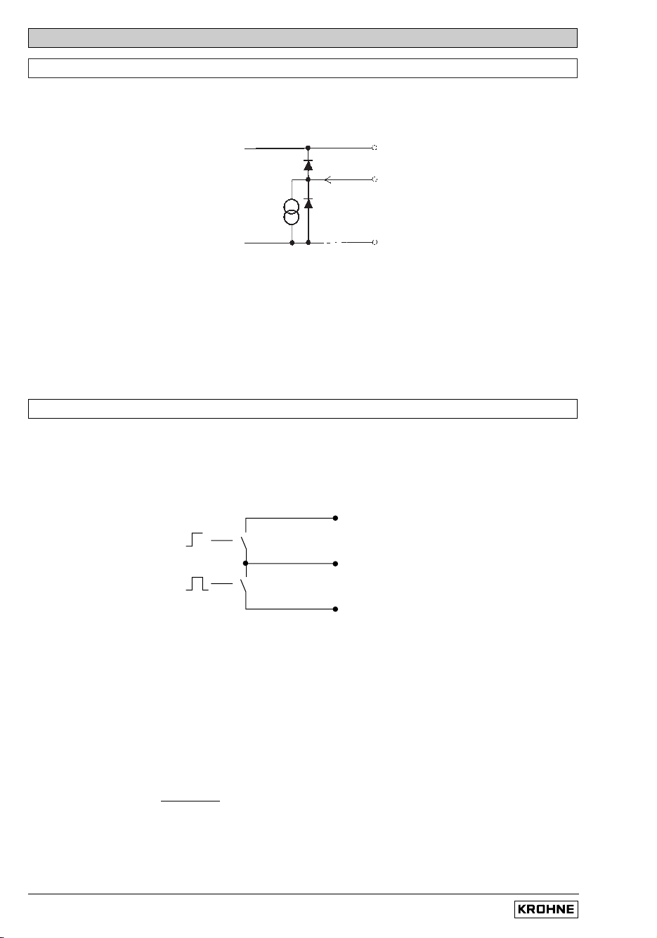
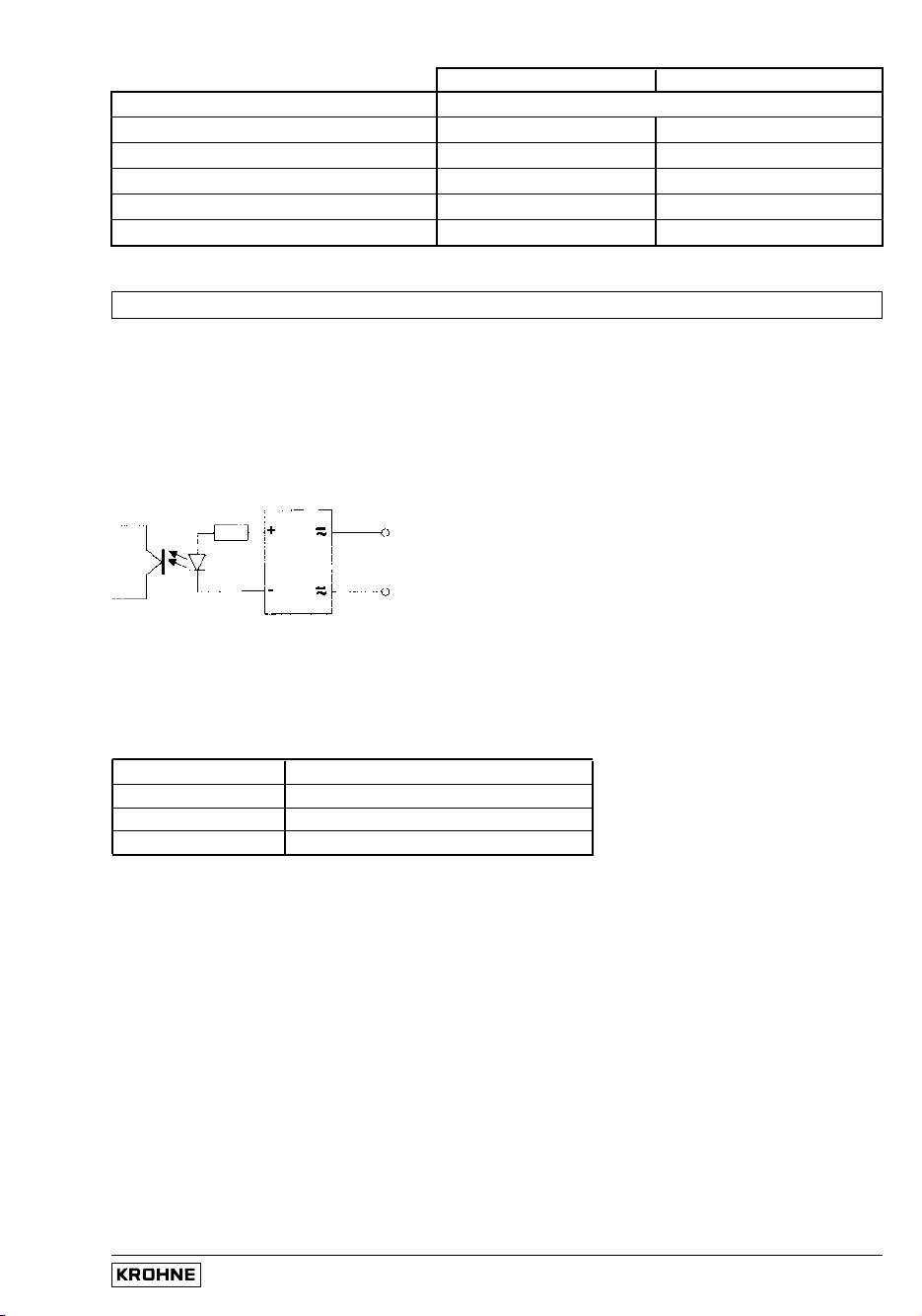
2.1 Current output I
• The current output is galvanically isolated from all input and output circuits.
• Factory-set data and functions can be noted down in Sect. 5.16.
Please also refer to Sect. 3.2 “Factory settings”.
• Typical current output
• All operating data and functions can be set: Operation see Section 4 and 5.6 Function 1.05.
• The current output can also be used as an internal voltage source for the outputs.
U
int
= 15 V DC I = 23 mA when operated without receiver instruments at the current output
I = 3 mA when operated with receiver instruments at the current output
•
Connection diagrams,
see Sect. 2.4: diagrams À Á Ã Å
• For
connection and operation with HART
®
-interface see Section 6.1.
I+ approx. 15 V DC positive
voltage of current output
I current sink
I⊥
chassis ground, current output
2 Electrical connection of outputs and inputs
2.2 Pulse output P and status output S
•
The pulse and status outputs are galvanically isolated from the current output and all input circuits.
•
Factory-set data and functions can be noted down in Sect. 5.16.
Please also refer to Sect. 3.2 “Factory settings”.
• Typical pulse and status outputs
S status output
P
⊥⊥
chassis ground
P pulse output
2/2
Installation and operating instructions IFC 020
Switch open Switch closed
OFF (switched off) without function
ON (e.g. operation indicator) Power supply OFF Power supply ON
F/R INDICATOR (F/R mode) Forward flow Reverse flow
TRIP POINT (Limit switch) Inactive Active
ALL ERRORS (all errors) Errors No errors
FATAL ERRORS (fatal errors only) Errors No errors
• Characteristics of the status outputs
Control input E (with IFC 020 E only) 2.3
• The control inputs are galvanically isolated from the current output and all input circuits.
•
Setting data and functions can be noted down in Section 5.16.
Please also refer to Sect. 3.2 “Factory settings”.
• Typical current input E
• All operating data and functions can be set:
Operation see Section 4 and 5.18 Fct. 1.08.
• The control inputs must be operated in the passive mode.
• Function of the control inputs
OFF switched off
TOTAL.RESET reset totalizer(s)
ERROR.RESET delete error messages
OUTP. HOLD hold value of outputs
Connection diagram, see Sect. 2.4: diagram
Æ
Z10
Z11

Installation and operating instructions IFC 020
2/3
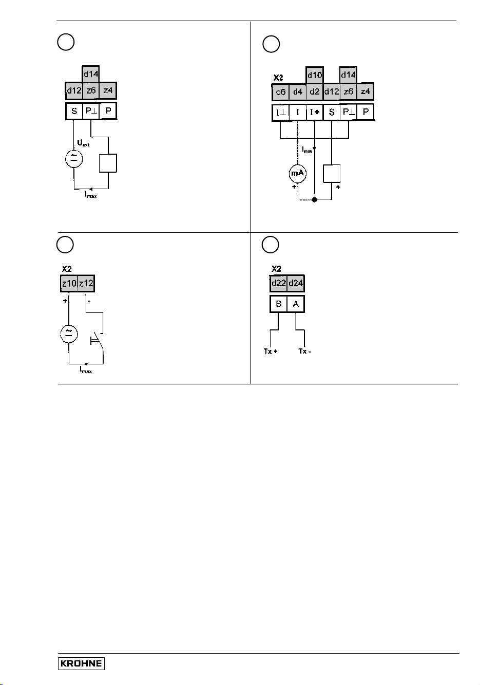
2.4 Input / output connection diagrams
Terminal identification
IFC 020 E
separated, 19” plug-in unit, connection cap X2
IFC 020 F separated, field housing
IFC 020 K compact
For connection and operation of the HART® interface,
see Section 6.1. Load at HART® operation ranges between min.
250 Ω and max. 500 Ω.
E: X2
F
K
I Current output C Control input (IFC 020 E only)
P Pulse output
S Status output RS 485 Interface
1 2
I = 0/4 - 20 mA
U
ext
15...20 V DC 20...32 V DC
R
i
0...500 Ω 250...750 Ω
U
ext
≤ 15 V DC
I = 0/4 - 20 mA
R
i
≤ 500 Ω
Current output
I
active
Current output
I
passive
Active mode
The current output supplies the power for
operation of the outputs and inputs.
Passive mode
External power source required for operation of
the outputs and inputs.
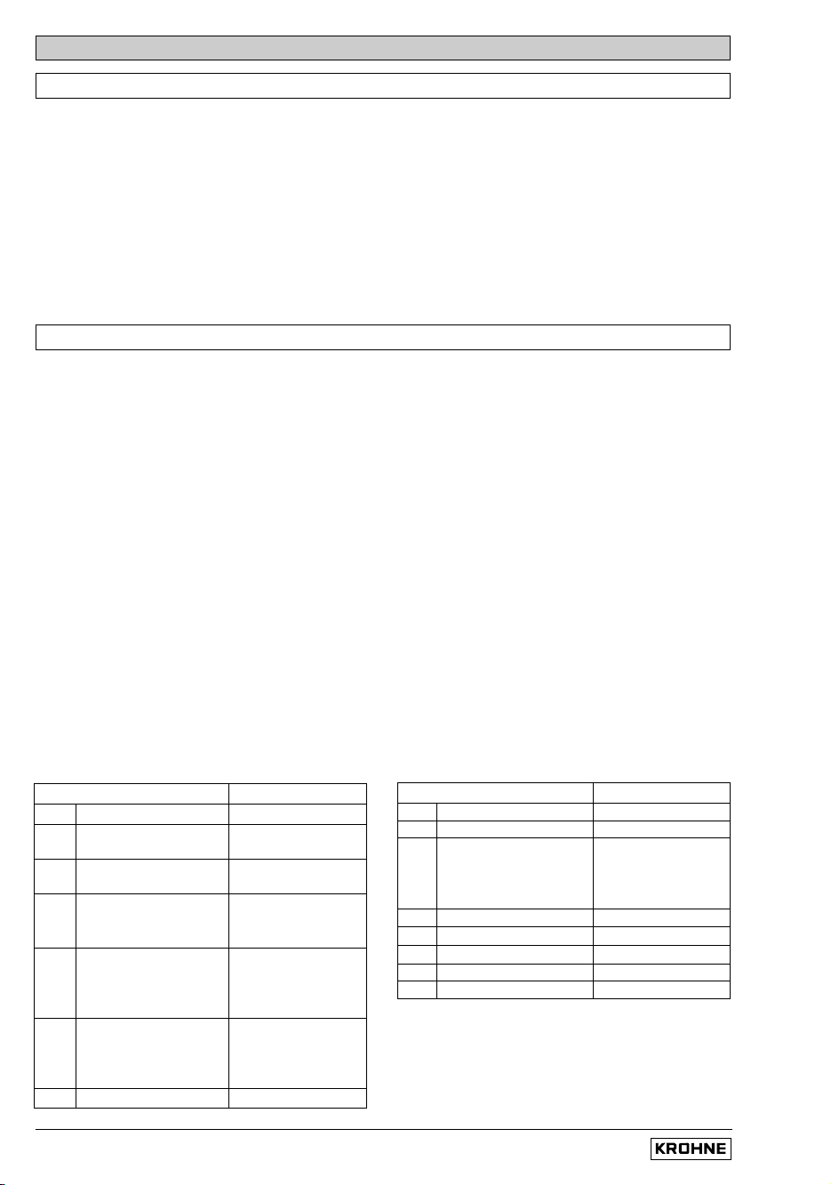
3 4
Pulse output P
passive
for electronic (EC) or
electromechanical (EMC) totalizers
U
ext
≤ 30 V DC/≤ 24 V AC
I
max
≤ 150 mA
(incl. status output S)
U
int
≤ 15 V DC from current output
Operation with current output:
I
max
≤ 3 mA
Operation without current output:
I
max
≤ 23 mA
R ≤
15 V
I
max
Pulse output P
active (and current output I
active
)
for electronic (EC) totalizers
with and without current output I
Totalizer
- electronic (EC)
- electromechanical (EMC)
Milliammeter
0 or 4-20mA and others
Key, N/O contact
External voltage source (U
ext
),
DC or AC voltage,
connection polarity arbitrary
DC voltage,
external power source (U
ext
),
note connection polarity
U
ext
U
ext
I
max
+
2/4
Installation and operating instructions IFC 020
U
ext
≤ 30 V DC/≤ 24 VAC
I
max
≤ 6 mA
87
Control input E
passive
(IFC 020 E only)
RS 485 Interface
For connection and
operation of the
Krohne RS 485
Interface,
see Section 6.2.
6
5
Status output S
passive
U
ext
≤ 30 V DC/≤ 24 V AC
I
max
≤ 150 mA
(incl. pulse output P)
Status output S
active
with and without current output I
U
int
≤ 15 V DC
from current output
I
max
≤ 3 mA
Operation with
current output
I
max
≤ 23 mA
Operation without
current output
Load
Load
Installation and operating instructions IFC 020
3/1
3 Start-up
• Before powering the system, please check that it has been correctly installed according
to Sect. 1 and 2.
• The flowmeter is delivered ready for operational use. All operating data have
been factory set in accordance with your specifications.
Please refer to Sect. 3.2 “factory settings”.
• Power the unit, and the flowmeter will immediately start process flow measurement.
• When powered, the display shows in succession: START UP and READY.
This is followed by display of the current flow rate and/or the current totalizer count
on either a continuous or alternating basis, depending on the setting under Fct. 1.04.
• Refer to Sect. 4 and 5 for operator control of the “display version”.
3.1 Power-on and measurement
3.2 Factory setting
All operating data are factory set according to your order specifications.
If you have not made any particular specifications at the time of ordering, the instruments will be
delivered with the standard parameters and functions listed in the Table below.
To facilitate easy and rapid initial start-up, current output and pulse output are set to process flow
measurement in “2 flow directions”, so that the current flowrate is displayed and the volumetric
flow counted independent of the flow direction. On instruments equipped with a display, measured
values may possibly be shown with a “ – ” sign.
This factory setting for the current and pulse outputs may possibly lead to measuring errors,
particularly in the case of volume flow counting:
for example, if pumps are switched off and a “backflow” occurs which is not within the range of the
low-flow cutoff (SMU), or if separate displays and counts are required for both flow directions.
To avoid faulty measurements, therefore, it may be necessary to change the factory setting of
some or all of the following functions:
– low-flow cutoff SMU, Fct. 1.03, Sect. 5.3
– current output I, Fct. 1.05, Sect. 5.6
– pulse output P, Fct. 1.06, Sect. 5.7
– display (option), Fct. 1.04, Sect. 5.4
Operation see Section 4 and 5.
Standard factory settings
Function Setting
1.01 Full-scale range Q
100%
see nameplate
1.02 Time constant 3 s, for I, S
and display
1.03 Low-flow ON: 1 %
cutoff SMU OFF: 2 %
1.04 Display (option)
flow rate m
3
/hr or US Gal/min
totalizer(s) m
3
or US Gal
1.05 Current output I
function 2 directions
range 4 - 20 mA
error message 22 mA
1.06 Pulse output P
function 2 directions
pulse value 1 pulse/s
pulse width 50 ms
1.07 Status output S flow directions
Function Setting
1.08 Control input off
3.01
Language for display only
English
3.02 Flowmeter
diameter see nameplate
flow direction (see arrow
+ direction
on primary head)
}
3.04 Entry code no
3.05 User unit
Liter/hror USMGal/day
3.06 Application steady
3.07 Measuring point Altometer
3.08 Communication interface off
3/2
Installation and operating instructions IFC 020
Here you can note down the settings of the signal converter !
Fct. No. Function Settings
1.01 Full-scale range
1.02 Time constant
1.03 Low-flow cut-off - ON: - OFF:
1.04 Display Flow
Totalizer
Messages
1.05 Current output I Function
Range I
Error
1.06 Pulse output P Function
Selection
Pulse width
Value
1.07 Status output S
1.08 Control input E (IFC 020 E only)
3.01 Language
3.02 Primary head Meter size
GK value
Field frequency
Power frequency
Flow direction
3.04 Entry code required ? - no - yes
→ → → ↵ ↵ ↵ ↑ ↑ ↑
3.05 User-defined unit
3.06 Application Flow is - steady
- pulsating
3.07 Measuring point
3.08 Communication interface
o
Off
o
HART
o
KROHNE RS 485
Address
Baud rate
Setting data 3.3
Installation and operating instructions IFC 020
4/1
4 Operation of the signal converter
Teil B IFC 020
_
/ D Signal converter
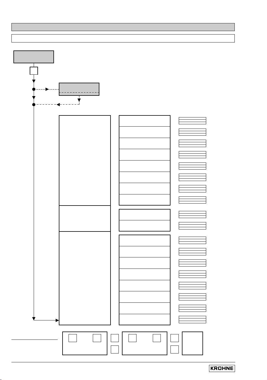
4.1 Krohne operator control concept
1 3 6. 4 9
m3/hr
Measuring mode
→
CodE 1
Menu column
Function column
Data column
3.00 INSTALL.
2.00 TEST
1.00 OPERATION
3.05 USER UNIT
3.06 APPLICATION
3.07 MES. POINT
3.08 COM
3.04 ENTRY CODE
3.03 ZERO SET
3.02 FLOWMETER
3.01 LANGUAGE
2.02 HARDW. INFO
2.01 TEST Q
1.07 STATUS S
1.08 CONTROL E
1.06 PULS OUTP. P
1.05 CUR. OUTP. I
1.04 DISPLAY
1.03 L.F. CUTOFF
1.02 TIMECONST.
1.01 FULL SCALE
Direction of movement
↓
↑
↑
↓
→
↵
↵
→
see
Sect.
4.4
When this display appears, press following keys:
→ → → ↵ ↵ ↵ ↑ ↑ ↑
Installation and operating instructions IFC 020
4/2
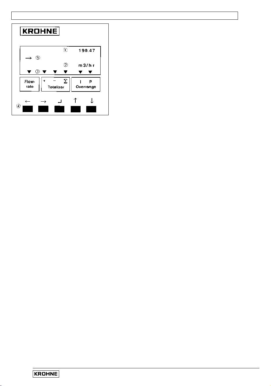
Operating and check elements 4.2
The controls are accessible after unscrewing the 4 screws and
removing the housing cover.
• Display, 1st line
‚ Display, 2nd line
ƒ Display, 3rd line: arrows to identify display
Flowrate current flowrate
Totalizer + totalizer
– totalizer
Σ sum totalizer (+ and –)
Overrange I overranging, current output I
P overranging, pulse output P
„ Keys for operator control of signal converter
… Compass field, signals actuation of a key.
IFC 020
S T O R E Y E S
F c t . 3. 0 0
INSTALL.
F c t . 1. 5
C U R R E N T I
FUNCT. I
F c t . 1. 5
C U R R E N T I
F c t . 1. 4
D I S P L A Y
F c t . 1. 0 0
O P E R AT I O N
Installation and operating instructions IFC 020
4/3
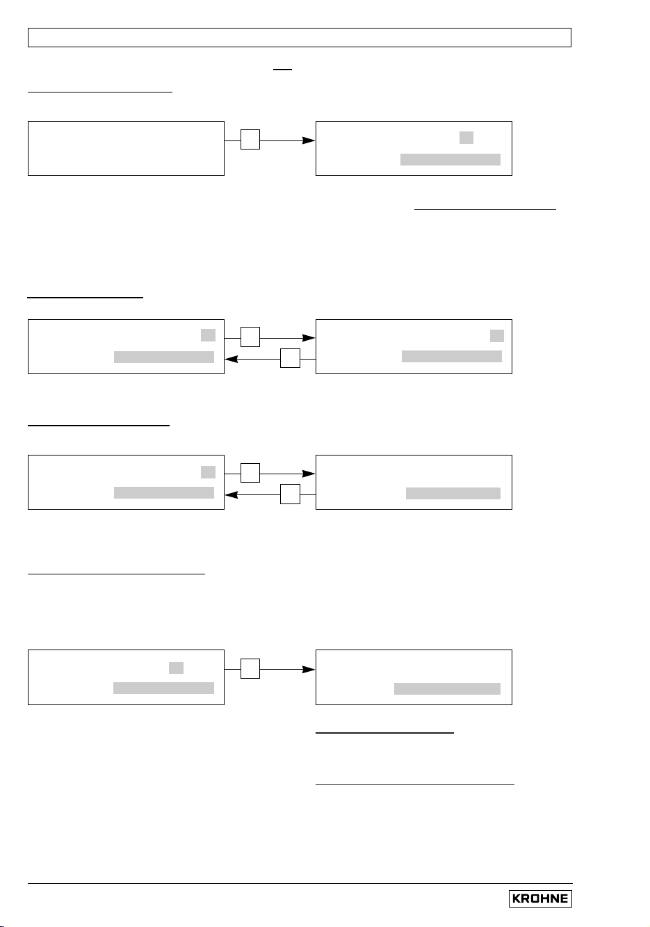
4.3 Function of keys
The cursor (flashing part of display) has a grey background in the following descriptions.
T
o start operator control
PLEASE NOTE: When “YES” is set under Fct. 3.04 ENTRY CODE, “CodE 1 - - - - - - - - -”
appears in the display after pressing the → key.
The 9-keystroke Entry Code 1 must now be entered: → → → ↵ ↵ ↵ ↑ ↑ ↑
(each keystroke acknowledged by “
*
”).
To terminate operator control
Press key ↵ repeatedly until one of the following menus
Fct. 1.00 OPERATION, Fct. 2.00 TEST or Fct. 3.00 INSTALL. is displayed.
↑
Increase number
T
o select a function
Decrease number
↓
→
Switch to function
T
o select a sub function
Return to function
↵
Measuring mode
1 3 . 5 7 1
m 3 / h r
→
Operator control mode
↵
Press key ↵
Store new parameters: acknowledge by
pressing key ↵ . Measuring mode continued
with the new parameters.
New parameters not to be stored:
press key ↑ to display „STORE.NO“.
Measuring mode continued with the „old“
parameters after pressing key ↵ .

1 D I R.
9 3. 3 6 5
U S. G a l / m i n
1 3. 5 7 1
m 3/hr
1 3. 5 7 1
m 3 / h r
3 9 7. 3 5
m 3 / h r
3 9 7. 3 5
m 3 / h r
3 9 7. 4 5
m 3 / h r
3 9 7. 3 5
m 3/hr
3. 7 6 9 9
L i t e r / S e c
1 0. 3
Sec
→
R A N G E I
F c t. 1. 02
T I M E C O N S T.
Installation and operating instructions IFC 020
4/4
↑
increase number
T
o change numbers
decrease number
↓
→
shift to right
T
o shift cursor (flashing position)
shift to left
←
↑
select next text
T
o alter texts (units)
For units, the numerical value is
converted automatically.
select preceding text
↓
→
Change to number setting
T
o transfer from text (unit) to number setting
Return to text setting
←
↵
To transfer to subfunction
Subfunctions do not have a “Fct.No.“ and are identified by a “ → ”.
↵
To revert to function display
Installation and operating instructions IFC 020
4/5
π
4
π
4
Q actual flowrate
Q
100%
100% flow = full scale range
Q
max
= DN
2
x v
max
/ max. full-scale range (Q
100%
)
at v
max
= 12 m/s / 40 ft/s
Q
min
= DN
2
x v
min
/ min. full-scale range (Q
100%
)
at v
min
= 0.3 m/s / 1 ft/s
S Status output
SMU Low-flow cutoff for I and P
v Flow velocity
v
max
Max. flow velocity (12 m/s / 40 ft/s) at Q
100%
v
min
Min. flow velocity (0.3 m/s / 1 ft/s) at Q
100%
F/R Forward/Reverse flow at F/R operation
π
4
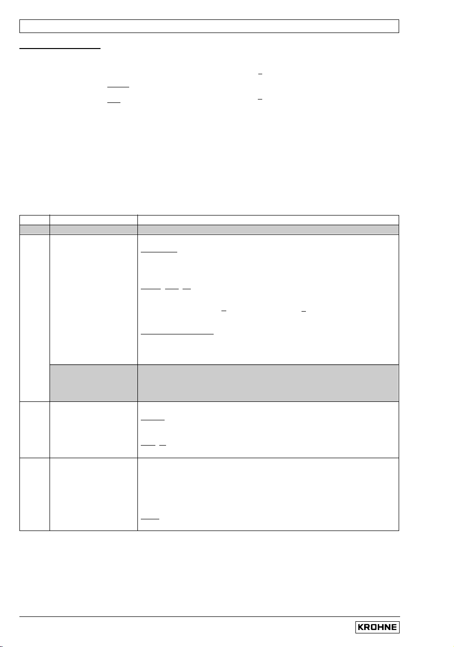
4.4 Table of settable functions
Abbreviations used
C Control input (IFC 020 E only)
DN Nominal size, meter size
F
max
Highest frequency of pulse output
F
min
Lowest frequency of pulse output
F
M
Conversion factor volume for any unit,
see Fct. “FACT. VOL.”
F
T
Conversion factor time for any unit,
see Fct. 3.05 “FACT. Time”
GK Primary constant
I Current output
I
0%
Current at 0% flow
I
100%
Current at 100% flow
P Pulse output
P
max
= F
max
/ Q
100%
P
min
= F
min
/ Q
100%
π
4
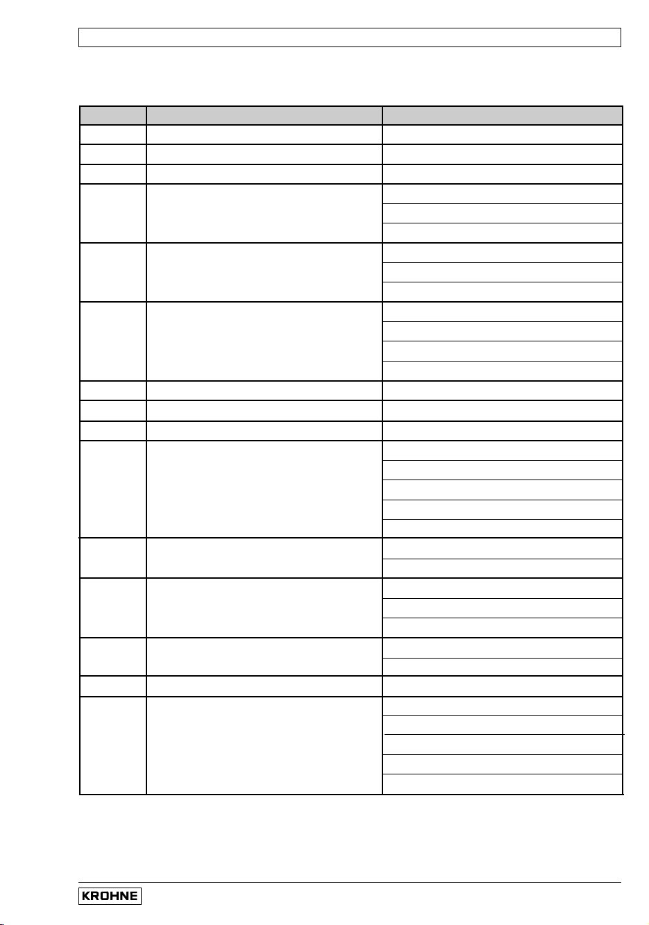
Fct. Text Description and settings
1.00 OPERATION Operations menu
1.01 FULL SCALE Full-scale range for flowrate Q
100%
Select unit
• m3/hr • Liter/Sec • US.Gal/min
• user unit, factory set is “Liter/hr” or “US MGal/day” (see Fct. 3.05)
Press → key to transfer to number setting.
Setting ranges
The ranges are dependent on the meter size (DN) and the flow
velocity (v): Q
min
= DN
2
x v
min
Q
max
= DN
2
x v
max
Nom. dia./meter size vmin = 0,3 m/s (1 ft/s) vmax = 12 m/s (40 ft/s)
•
DN 2.5–1000 /
1
/
10
”–40”: 0.0053 – 033 900 m
3
/hr
0.0237 – 152 000 US.Gal/min
Press ↵ key to return to Fct. 1.01 FULL SCALE.
→ VALUE P Pulse value (Fct. 1.06
“VALUE P”
) has been changed.
With the “old” pulse values the output frequency (F)
would have been exceeded or not reached.
P
min
= F
min
/ Q
100%
P
max
= F
max
/ Q
100%
Check new values!
1.02 TIMECONST. Time constant
Select:
• ALL (applies to display and all outputs)
• ONLY I+S (only display, current and status outputs)
Press ↵ key to transfer to number setting.
Range: • 0.2 – 99.9 Sec
Press ↵ key to return to Fct. 1.02 TIMECONST.
1.03 L.F.CUTOFF Low-flow cutoff (SMU)
• OFF (fixed values: ON = 0.1% / OFF = 0.2%
at 100Hz and 1000Hz, see Fct. 106, 1% resp. 2%)
• PERCENT (variable values) ON OFF
1 – 19% 2 – 20%
Press → key to transfer to number setting.
Note:
Cutoff “off” value must be greater than cutoff “on” value.
Press ↵ key to return to Fct. 1.03 L.F. CUTOFF.
 Loading...